Week 16: Interface and Application Programming
Individual assignment
This week we will work on an interpret and implement design and programming protocols to create a Graphic User Interface (GUI).
ATmega328 & LDR sensor
For this week I will use and modify some entries of the Atmega328 board designed by Edwin Alvrez
 Fig.01 - Schematic ATmega328 v3
 I increased the GND and VCC entries which I am considering for my final project. Once connected the board would look something like this
 Download SCH & BRD
 Fig.02 - Board ATmega328 v3
Once the image is exported in png format, the image is entered on the page of FabModules to generate the g-code with PCB traces (1/64) the following parameters were used to cut it in the CNC: Spindle speed (8000RPM), tool diameter (0.1mm) and numer of offsets (15).
 Download PNG
 Fig.03 - Fab Modules
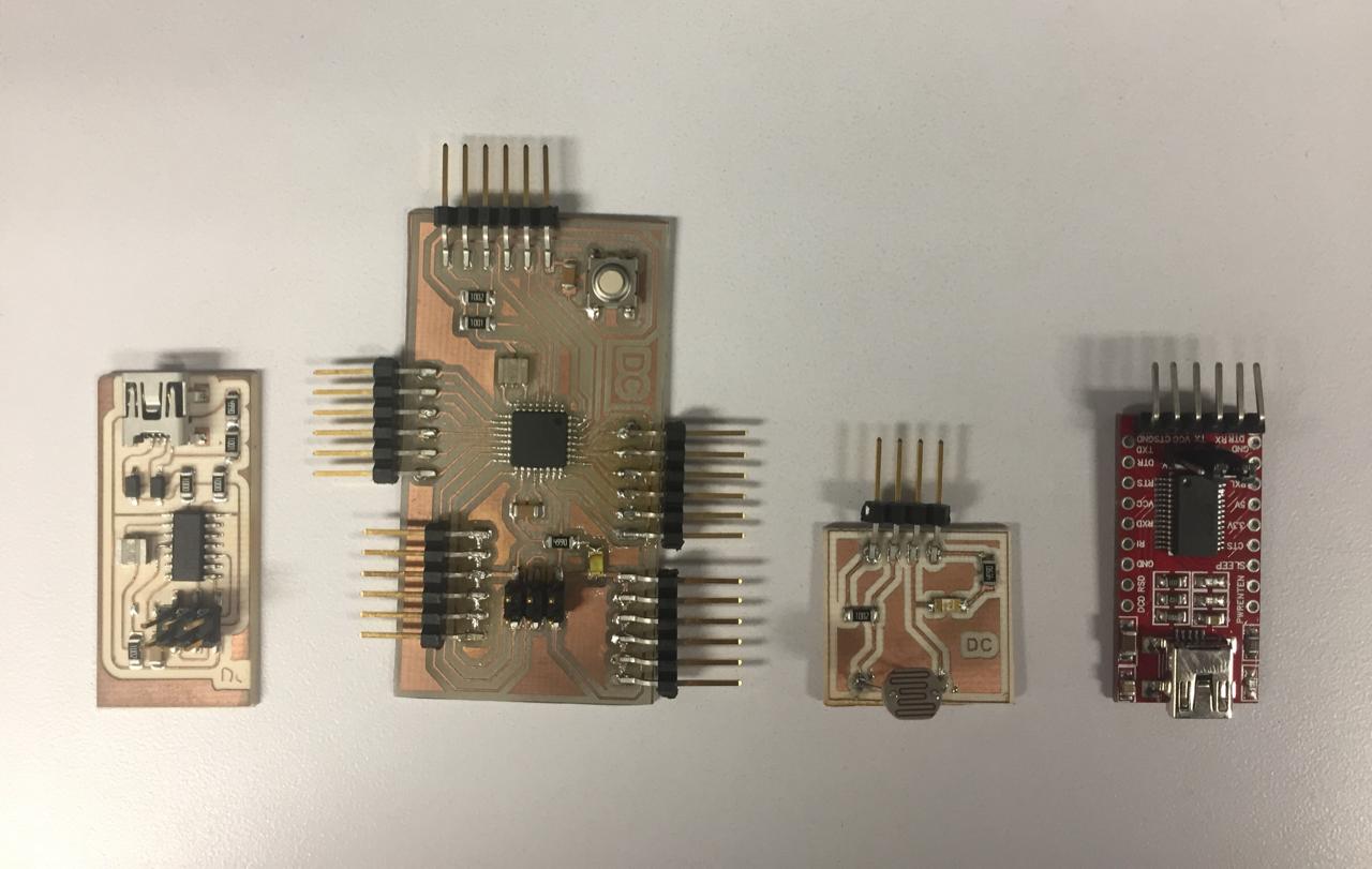
For the cutting of the board the Roland Modela-540 was used, once the board was cut it was soldered with flux, it was a difficult process to solder the microcontroller 328. The most feasible was to do an inverse process like covering the area with flux and Then remove with a clamp the material that is outside the rails.
 Download Code-G ATmega328
 Fig.04 - Board
I will use a light sensor that allows me to generate the movement that we want in the interface. For this I will create a board that has an LED that tells me if the amount of light exceeds the configured and an LDR sensor.
 Download G-Code LDR,LED
 Fig.07 - Code
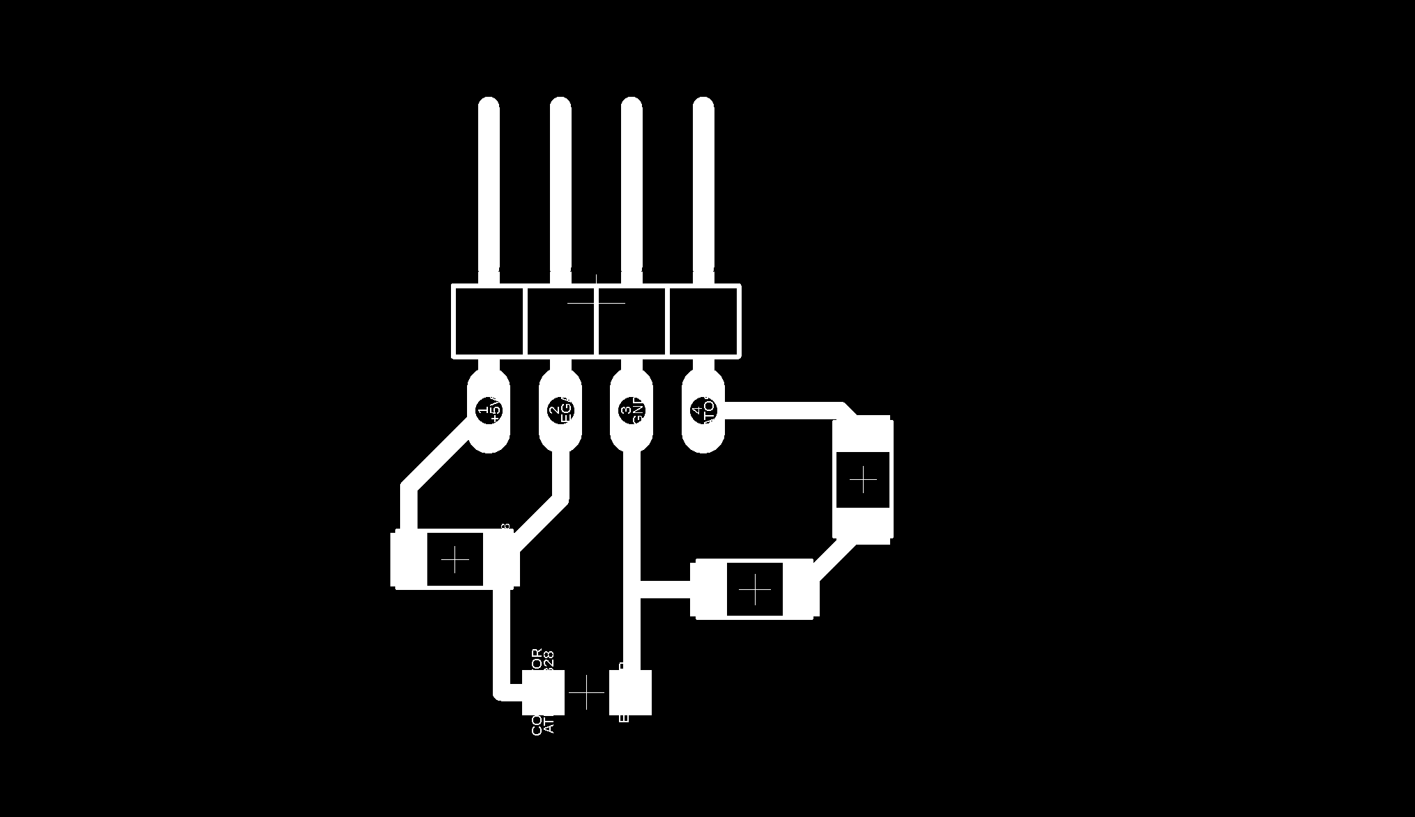
Like the ATMega I'm going to cut it with the same parameters: Spindle speed (8000RPM), tool diameter (0.1mm) and numer of offsets (15).
 Download PNG - LDR,LED
 Fig.06 - Fab Modules
To be able to use the firefly, it is necessary to have an Atmega328 board, the ISP as a power source, an LDR sensor, the FTDI that will allow reading the USB port and a block that represents the servomotor component which will move and generate the interface. graphic.
 Download Servo Component design in rhinoceros
 Fig.08 - Components
Firefly
I'm going to create a user interface graphic with Firefly, for that I download the program from the page Firefly Experiments.
Firefly offers a set of comprehensive software tools dedicated to bridging the gap between Grasshopper (a free plug-in for Rhino) and the Arduino micro-controller. It allows near real-time data flow between the digital and physical worlds – enabling the possibility to explore virtual and physical prototypes with unprecedented fluidity.
 Fig.09 - Firefly
 Once the program is installed, the interface opens from grasshopper and the firefly window will look like in the image.
 Fig.10 - Firefly Interface
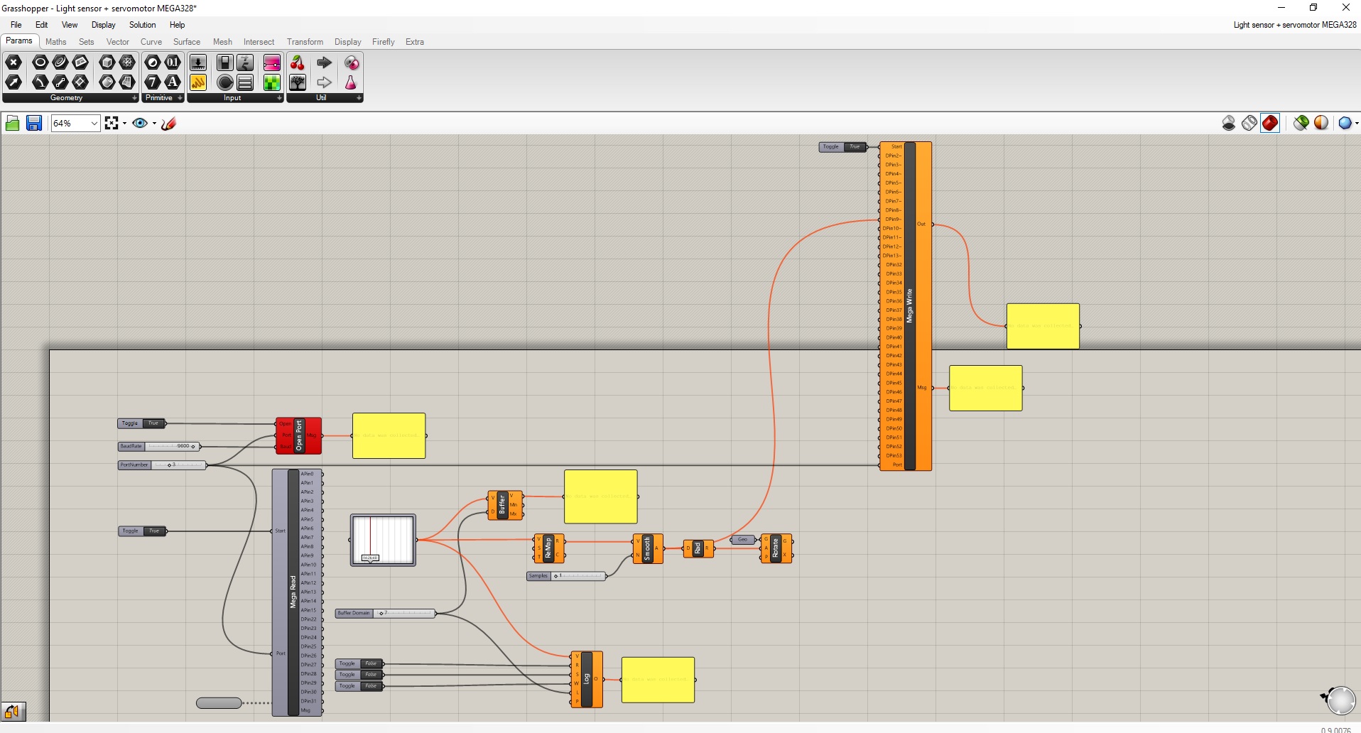
 I will make a representation of the movement of the motors that I will use in my final project, for this I need to configure the firefly architecture. As a first step, we will insert the MegaRead tool that corresponds to the ATmega 328 board data; then, we will use the ReMap tool to create a domain number reading and we will add the rotation that will be subject to the rhinoceros 3D graphic. Finally we insert the MegaWrite tool to observe the data that originates.
 Download Firefly File
 Fig.11 - Firefly File
When you connect the board, note that you did not have the atmega328 drivers, so you can install it.tutorial by Carlos Efr. Then, I added the programming to the microcontroller that includes the movement of the servomotor and control of voltage greater than 45 so that it turns on and off when the servo turns.
 Download Arduino Files
 Fig.12 - Arduino Files
In the video we can see how the Graphic User Interface was created using firefly. With a flashlight we manage to generate the movement that should be established in my final project.
It is very important to have the Toggle tool turned off in order to load a new schedule and turn it on after completing the upload process. In addition, the microcontroller to be used should be considered if it is ONE, MEGA and DUE
 Fig.13 - Firefly Suggestions
 To see all the documentation of the group work, you can visit the CIT page.