
Input devices.
For the assignment of the 11th week: Inputs devices, it will be divided into 6 parts: Sensors, Board, Programming, Problems, Group and Download.
Sensors
Sensors are devices that measure different variables such as: temperature, pressure, distance, presence, etc. Most of these sensors are analog elements, since they can measure up to infinite possible values, for example the temperature: 26ºC, 18.5ºC, 41.4ºC, etc.While other sensors have a digital behavior, that is to say that there are only two possible values: yes or no. For example, a button, presence sensor, etc.
In our laboratory we have the following sensors:
| Sensor | Type | Fuction |
|---|---|---|
| ADXL 343B | Analogic | Accelerometer |
| Microphone 22dB | Analogic | Microphone |
| LDR | Analogic | Photoresistor |
| Button | Digital | Button |
| Potentiometer | Analogic | Variable resistor |
| Lm35 | Analogic | Temperature sensor |
| Thermistor 10k | Analogic | Temperature sensor |
| Hall Sensor | Analogic | Measure magnetic field |
| RTD | Analogic | Temperature sensor |
 The operation of the thermistor is quite basic, when the resistance is in contact, it will raise its temperature according to the following graph.
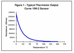
Source: http://www.bapihvac.com/wp-content/uploads/2010/11/Thermistor_100K.pdf
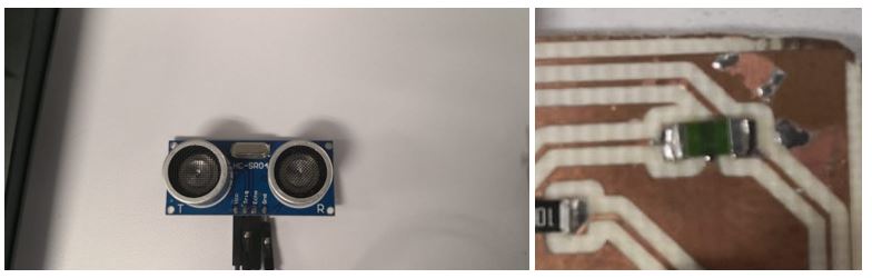
The operation of the ultrasonic sensor is different, the transmitter (trig pin) sends a signal: a high-frequency sound, when the signal finds an object, it is reflected and the transmitter (echo pin) receives it. The time it takes for the signal to arrive is what indicates the distance of the object. <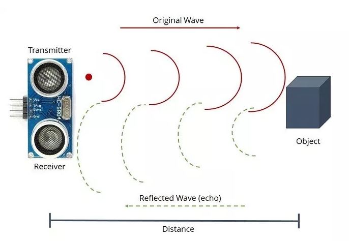
Source: https://randomnerdtutorials.com/complete-guide-for-ultrasonic-sensor-hc-sr04/
The choice of these sensors is aligned with my final project, since I have to measure the water temperature of the steaming machine and the amount of water that exists in the tank with the presence sensor.Analog Digital Converter (ADC)
The ADC contains a Sample and Hold circuit which ensures that the input voltage to the ADC is held at a constant level during conversion.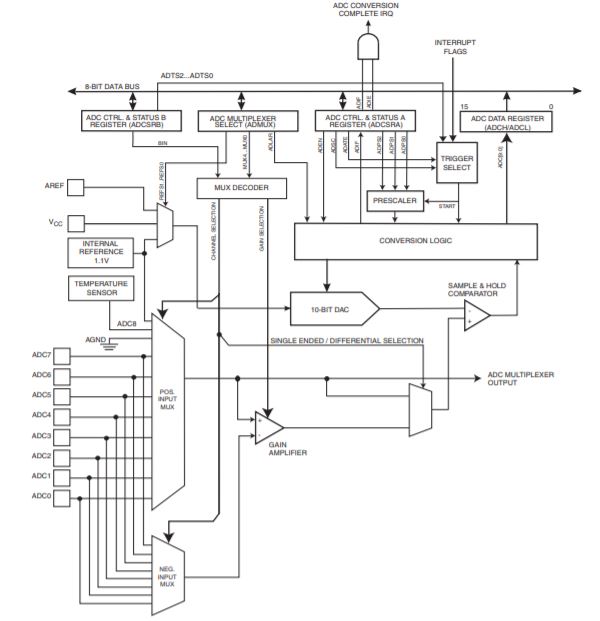 The ADC converts an analog input voltage to a 10-bit digital value through successive approximation. The minimum value represents GND and the maximum value represents the reference voltage.
These values are within the microcontroller ranging from 0 to 1023, representing 0V and 5V respectively.
The ADC converts an analog input voltage to a 10-bit digital value through successive approximation. The minimum value represents GND and the maximum value represents the reference voltage.
These values are within the microcontroller ranging from 0 to 1023, representing 0V and 5V respectively.Board
As described above, I have decided to use an analog and a digital sensor, as I will use these sensors for my final project. Therefore, I reread the attiny44's datasheet to know how to use the analog and digital input pins.The attiny44 has a total of 7 analog pins, internally it has a digital analog converter (ADC) which will help us to interpret the analog sensor in a better way.
There is a table on page 180 of the data sheets that indicates the maximum value that the ADC can have is 1023, which would be the analog value of the maximum input voltage, in this case it will be 5VDC. In other words, it means that the analog pins will have values between 0 and 1023, which would be from 0 to 5VDC. With programming we must convert this measure into a value that we can understand using different formulas.
On page 55 of the data sheet they mention that digital pins are bidirectional, that means they can serve as inputs and outputs. We remember the hello world board in which we use a led as a digital output and the button as a digital input, only its operation is configured on setup as input or output.
Only in case analog pins work only as inputs, they cannot be outputs. In case of wanting to use an analog output, we must use the PWM pins of the microcontroller.
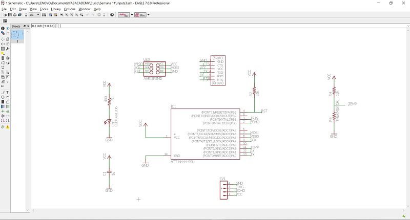
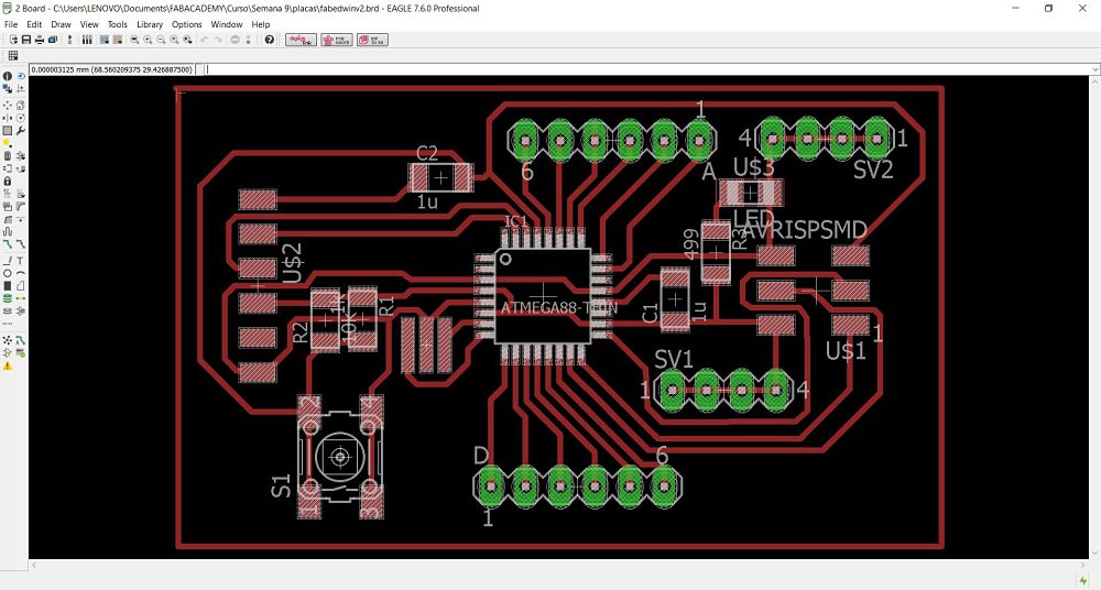
With these previous concepts, we proceed to make the schematic of our inputs board, remaining as the next picture.
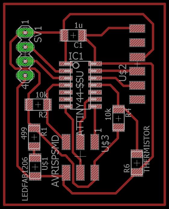
 We remember from week 7, the attiny44 has a small internal clock of 8MHZ, for that reason I save the resonator and take both pins for the ultrasonic sensor and make a smaller board.
The final board is shown in the following picture.
We remember from week 7, the attiny44 has a small internal clock of 8MHZ, for that reason I save the resonator and take both pins for the ultrasonic sensor and make a smaller board.
The final board is shown in the following picture.
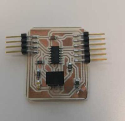
 We start with the manufacturing and soldering process, having the following result.
Programming
As it was done in the week of the programming, it is necessary to make a connection of the manufactured board, the ISP to burn the bootloader and the FTDI to load the program to the microcontroller. The final wiring with the included sensor is as follow picture: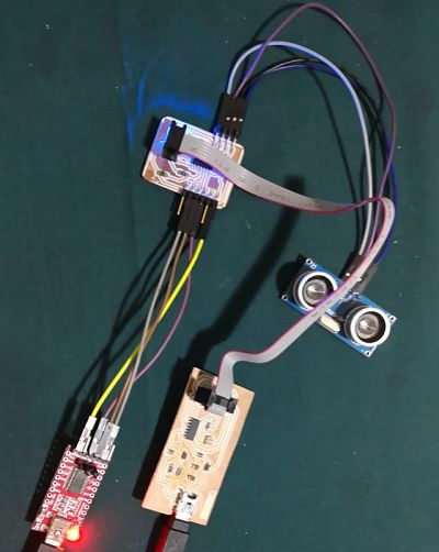 Now, it is time to programming both sensors.
HC-SR04
The first test is the distance sensor, I work with these one several times, for that reason it was the first one. In my board I did not use a led for output, so I only use the software serial monitor to see my distance.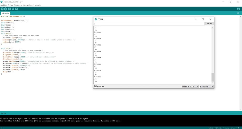 Here is the code.
#include

SoftwareSerial monserial(0, 1);
long distancia;
long tiempo;
int trigger=10;
int echo=9;
void setup() {
  // put your setup code here, to run once:
  monserial.begin(9600);
  pinMode(trigger, OUTPUT);
  pinMode(echo, INPUT);
}

void loop() {
  // put your main code here, to run repeatedly:
  digitalWrite(trigger,LOW);
  delayMicroseconds(5);
  digitalWrite(trigger,HIGH);
  delayMicroseconds(10);
  tiempo=pulseIn(echo,HIGH);
  distancia= int(0.0175*tiempo);
  monserial.println("Distance ");
  monserial.println(distancia);
  monserial.println(" cm");
  delay(500);
}
Thermistor
For this case, I use this tutorial to programming my temperature sensor. These was the formula:reading = (1023.0 / value) - 2.0;
temp = reading*100.0;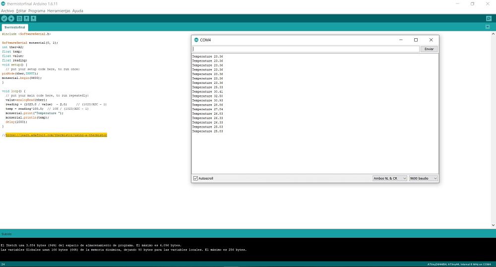 Here is the code:
#include
SoftwareSerial monserial(0, 1);
int ther=A2;
float temp;
float value;
float reading;
void setup() {
pinMode(ther,INPUT);
monserial.begin(9600);
}
void loop() {
// put your main code here, to run repeatedly:
value=analogRead(ther);
reading = (1023.0 / value)  - 2.0;
temp = reading*100.0;
monserial.print("Temperature ");
monserial.println(temp);
delay(1000);
} Both sensors
I try to make an only program, but I have a critical problem. The software serial library uses a lot of the internal memory, my programs are too heavy for the attiny44.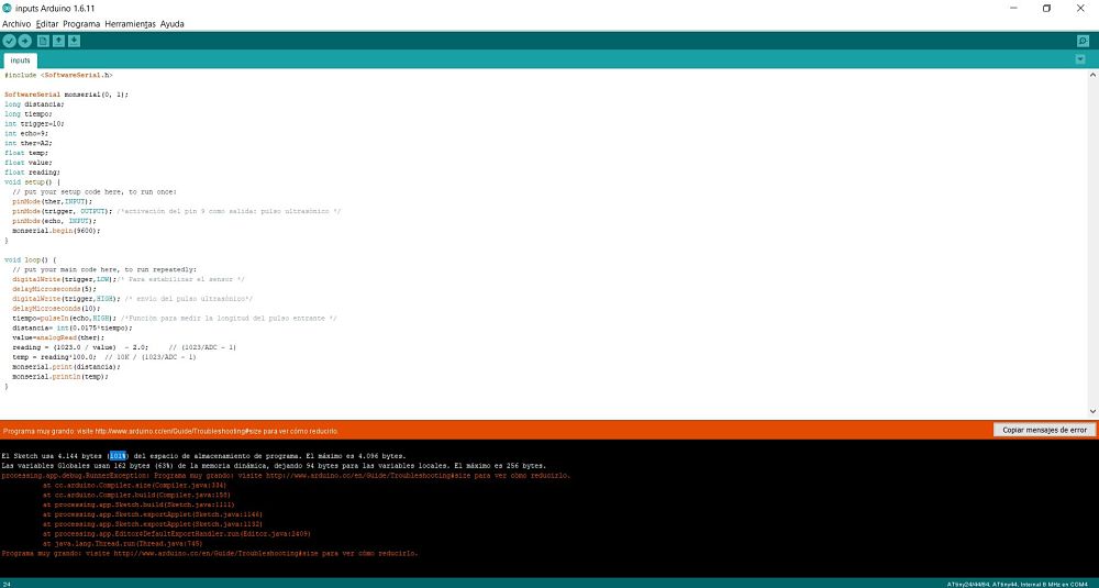 For my final project I need another board, because the memory is very small for all the process, I try another atmega328 version.
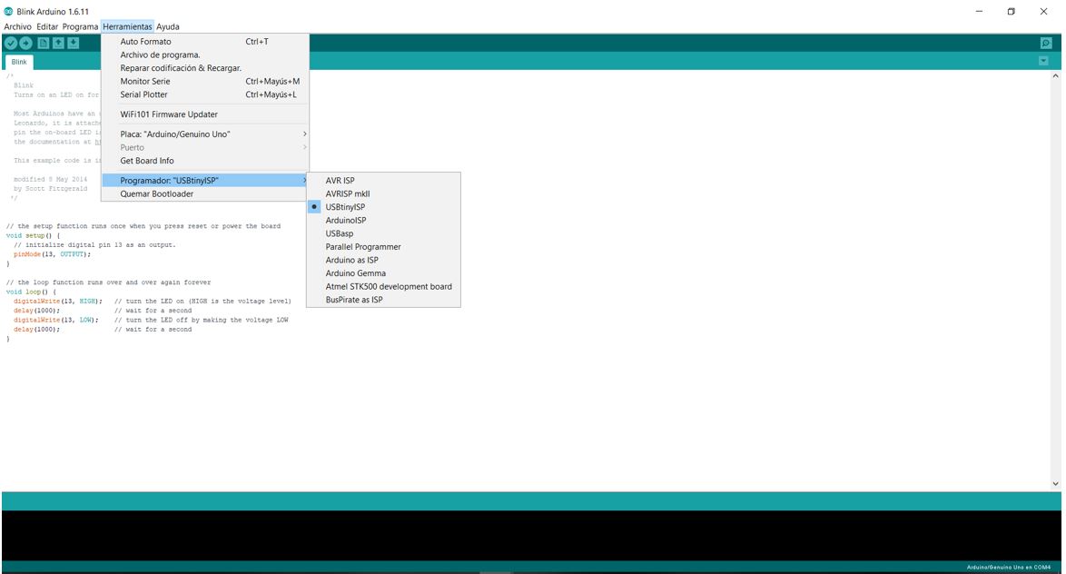
 In this version I use some pins to Vcc and GND for some sensors. To upload a code to the atmega328, is necessary to use this configuration:
- Board: Arduino uno.
- Programmer: USBtinyISP.
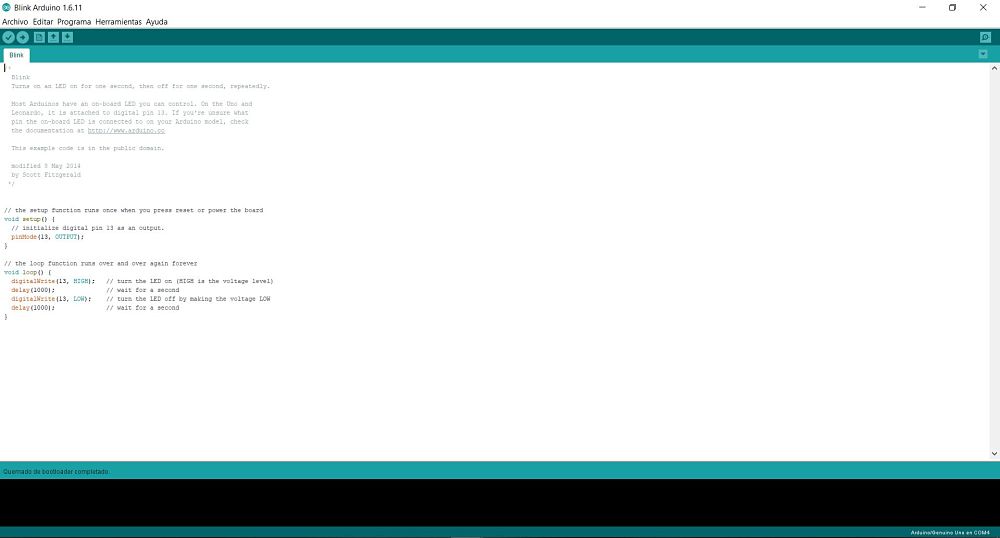
 I connect my ISP and FTDI to upload a simple blink, but I have some problems. It’s possible to burn the bootloader.
 When I try to upload my code, I have an error:
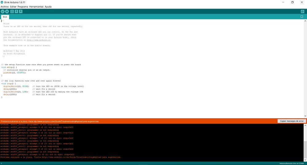 I will review my schematic one more time to find the problem, I try to use finally my atmega board to the output board for the next week.
In the following video we can see the operation of both sensors separately.
Problems
In programming the temperature sensor, I used some work codes from years past of various fabacademy students, but when using the software, I always had problems with memory space, as seen in the picture.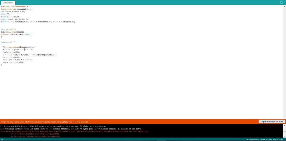 That was the main reason to investigate various codes to get one that approximates the actual temperature. For my project I will use other types of more commercial sensors, which has a simpler measurement as well as a conversion formula easier to interpret and modify.
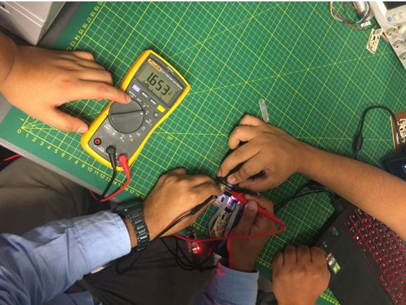
Group
The group task of the week is to measure the consumption values of the inputs board. As a personal contribution of the group work I made the design of the group board, as shown in the picture.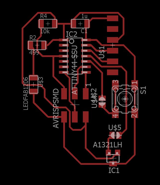 From this design, we proceed to make the consumption measures, as shown in the following picture.
We also use an oscilloscope to measure both sensors.
To see all the documentation of the group work, you can visit the CIT page.
Download files
You can download files Here:Code
Thermistor code
Distance code
Distance and Thermistor code
Board
Schematic design
Board design
Manufacturing
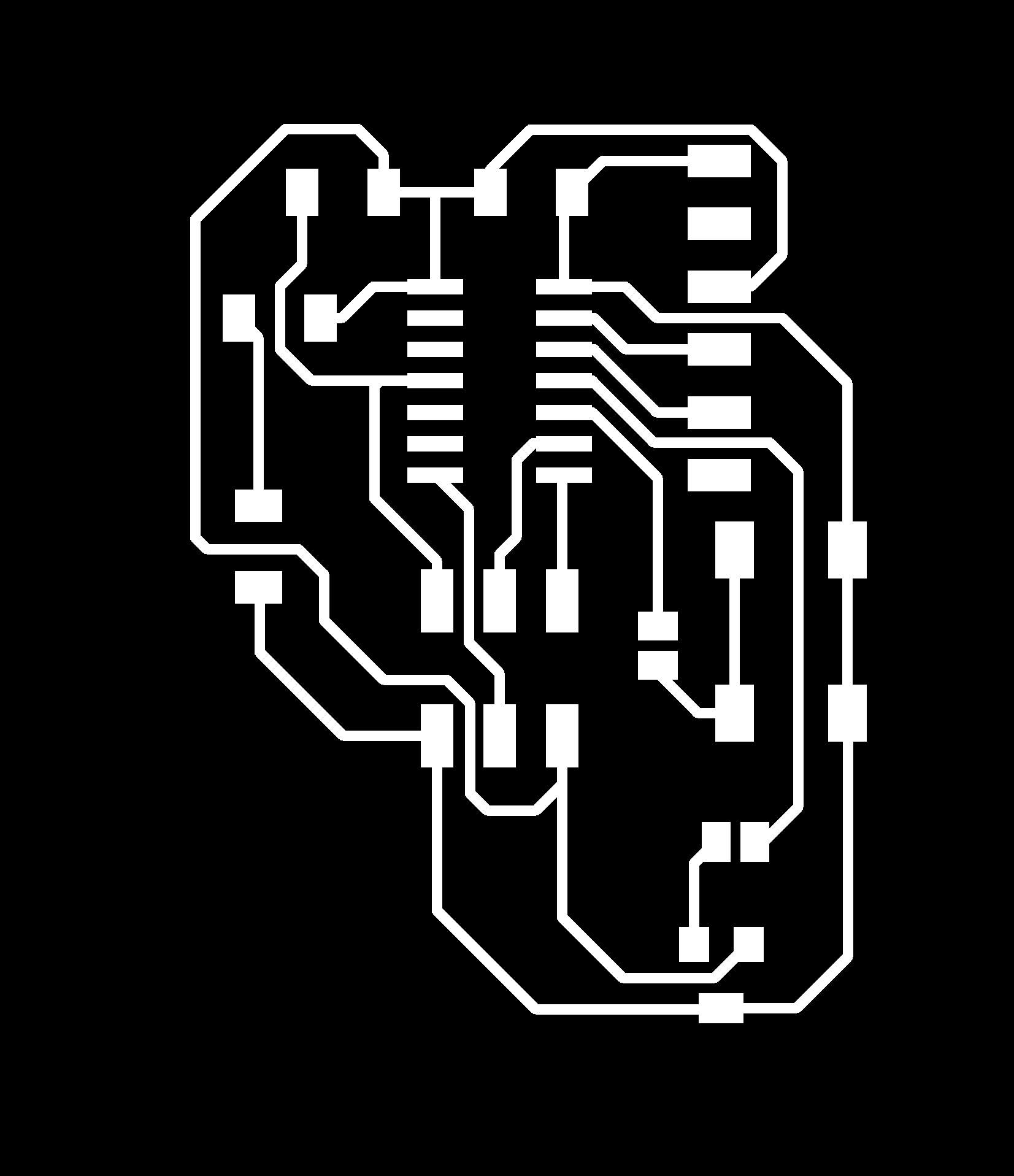
Traces
Out
Atmega328 version 2
Schematic design
Board design
Grupal
Schematic design
Board design
Traces
Out
Sensor Hall code
Button code