Input devices
Group assignment
Sensors
Hall effect sensor
As an analog input, we use the A1324 sensor, also known as the hall sensor. The function of this sensor will be to measure the electromagnetic fields, for these tests we will use a small magnet of a magnetic lock.
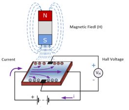
As the electromagnetic field approaches, the output will have a greater or lesser voltage depending on the distance.
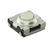
SourceButton
The button is a contact sensor, which allows to pass or cut the electrical current, this button has been used for week 7
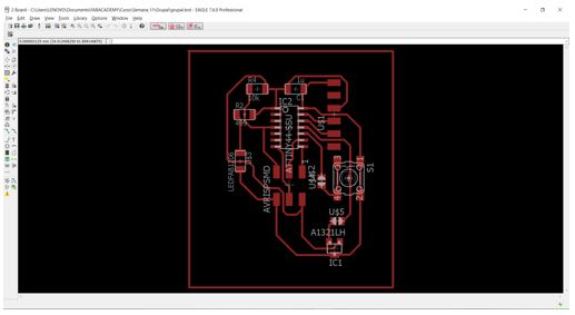
Design After the experience acquired in the manufacture of plates, the following schematic circuit is created contemplating both inputs, being a digital and an analogue one.
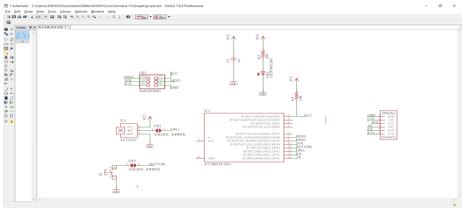
Once the schematic is finished, we proceed to design the board, having the following scheme.
Programming and measurement button
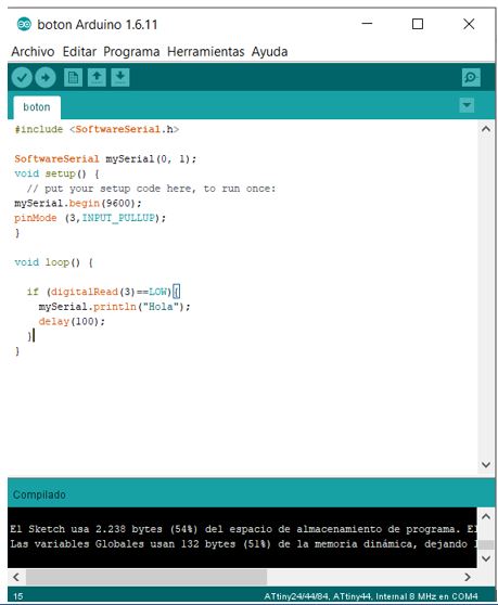
The first example we are going to use is the pushbutton, as shown in the schematic, we do not use a resistor to create the pull_up configuration, but we will use the internal configuration of the pinMode directly with the following simple code.
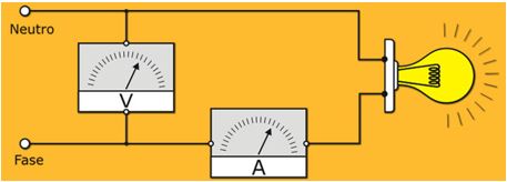
Taking advantage of the welding bridge created near the button, we proceed to connect the multimer to measure voltage and current according to the following scheme
Source
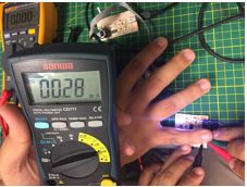
The measurements are taken as shown in the images:
Voltage
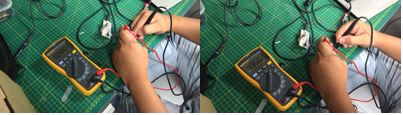
When pressing the button, we have a voltage of 4.95V and if we do not keep it pressed it gives us a voltage of 0V.
Current
In this case, the measurement always gives us 0A since, having only the button and with the internal configuration as pull_up, there is no opposition of electric current as could be caused by an electrical resistance. For this case, the current will be measured by an analog sensor.
Programming and measurement sensor effect hall
Voltage
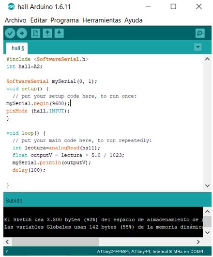
To voltage measurement, we will use the following code as a test with a formula for converting the measured variable into a voltage:
We proceed to measure the voltage with the help of the multimeter and compare the result with the code:
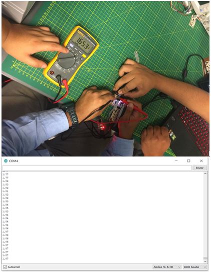
They give us values very similar to the result obtained by the code and by the same measurement instrument, in this way we can adjust the formula to obtain a more precise data. The measured voltage ranges between 2.5V and 0V. As a curious fact of the experiment, we can visualize a measurement of 0V when we place both magnets between the hall sensor, this is because the field is counteracted in the middle of the magnets.

Current
At the moment of making the plate and placing the welding bridges, the sensor's datasheet was not taken into account, since it shows us the values of the currents that they must have and where to measure them.
According to the
DatasheetThe currents must be measured between the pins of Vout with Gnd and Vcc with Vout.
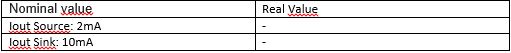
We can see that the values are very similar, this is because we are not using the same values of the datasheet: the voltage is different from the nominal value of the sensor.
Input devices of Danny
To perform a new current test, we will use the example of Danny. since he used an LDR as an input sensor, the measured current values are as follows:
LED ON 46 mA

LED OFF 28 mA