Week 08: Computer-Controlled Machining
The purpose of this week is to make something big on a CNC machine. Demonstrate 2D design development and describe workflows for CNC production.
Individual assignment
2D Design
I'm going to create a portable ledge that can be built from several pieces, so you do not have a problem when moving. For this, I will use the rhinoceros program, which allows me to work with complex geometries.
This furniture will go into a corner of an office, as a first step it is necessary to obtain some measurements to get an idea of the furniture dimension.
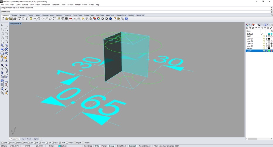 Fig.01 - Rhinoceros Design
 I created the curves of the furniture with the tool "tweencurves", since it allows me to control the variation between the first and last curve. Thus I generate all the levels of the shelf. Nevertheless, I generate vertical supports and I direct them to a specific point, that the piece of furniture presents a vanishing point.
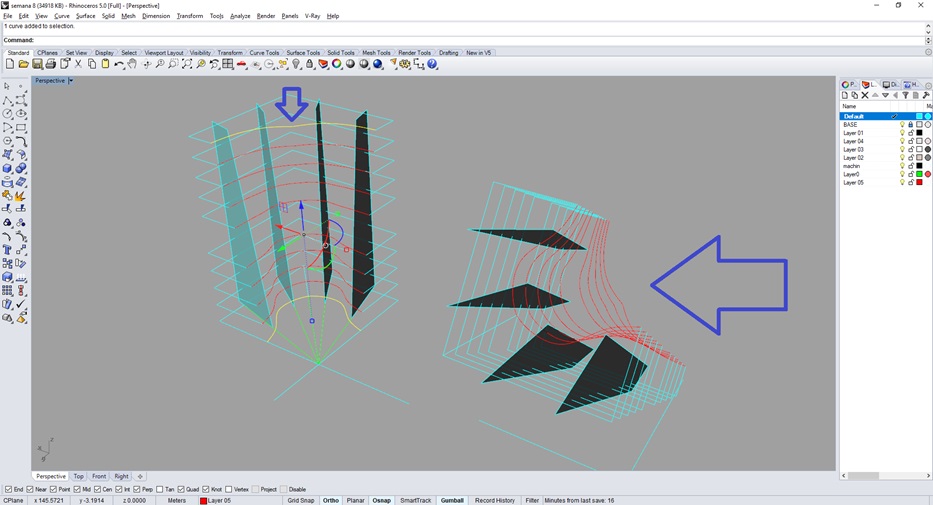 Fig.02 - TweenCurves
 The levels of the ledge will have divisions that together will reach a height of 1.80m. To have a better presicion I will generate the dimension of the material, in this case for the vertical supports use MDF of 18mm and for the horizontal bases MDF of 12mm. With the tool "planarsrf" we generate the thickness.
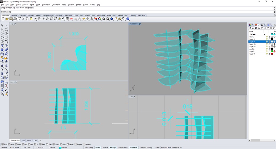 Fig.03 - Planar Surface
 With the "BooleanDifference" command, the vertical supports are subtracted to generate the piece with exact dimensions. I recommend generating a copy so as not to lose the initial prototype.
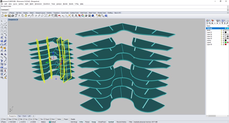 Fig.04 - Boolean Difference
 In the vertical support I will generate a design with voronoi, I thought I would generate it with a parametric pattern, but this time I will show that it can also be done manually. To do this, I need the piece with the slots (1), I generate a voronoi pattern with a vertical volume greater than the piece (2), I arrange them without obstructing the slots (3) and finally I use the tool "boleandifference" with both solids (4). The result is amazing and faster than generating parametric patterns from grasshopper.
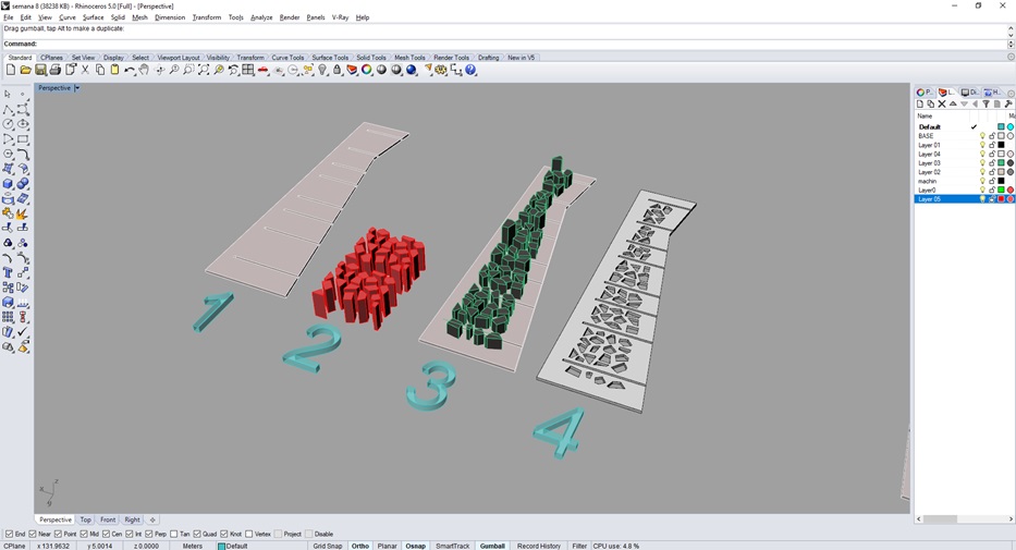 Fig.05 - Voronoi Design
 To obtain the pieces of the 3D model, use the tool "unrollsurface" or default "smash", but the latter messes up the pieces or inverts them as if we were using the "mirror" tool.
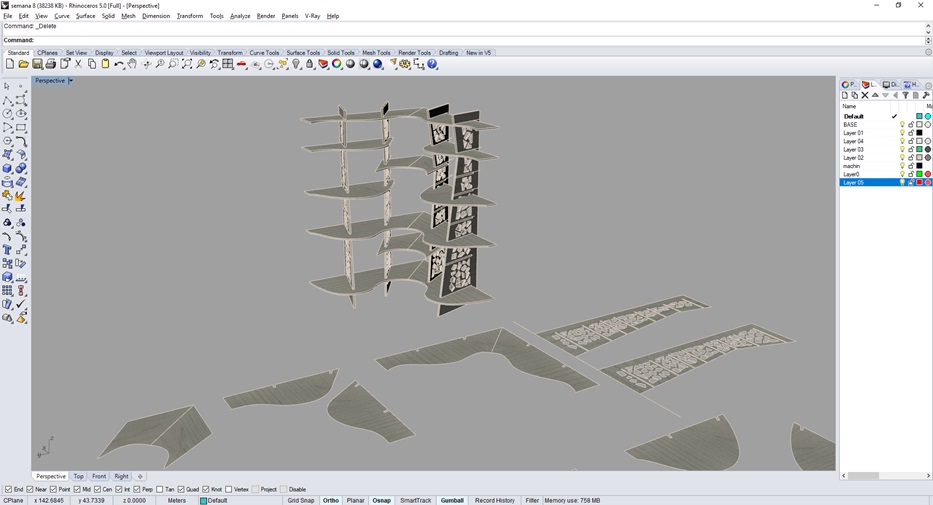 Fig.06 - Make 3D to 2D
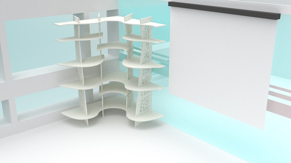
 The furniture that I will create would be this way.
Download Rhino Files
Fig.07 - 3D Design
The CNC router software works with .dwg .dfx extensions, so I decided to import the parts to the AutoCAD program. In this work the slots, the milling machine with which I will work is 3/16" or 4.76mm.To avoid that the machine is cutting circles and lengthen the cutting process, our local instructor Alejandro Otazú told us that we must make some steps to generate stability in the slots.
First, we must create a circumference of 4.8mm in diameter at the corners and look for the midpoint between perpendicular radii (1); Second, the intersection of the radius will generate the new center of a circle of diameter 5mm that will originate the exact width for the mill have a uniform path (2); Finally, we suppress to generate the new opening of the piece (Dogbones) and when measuring this the width is of the bit 4.8mm.
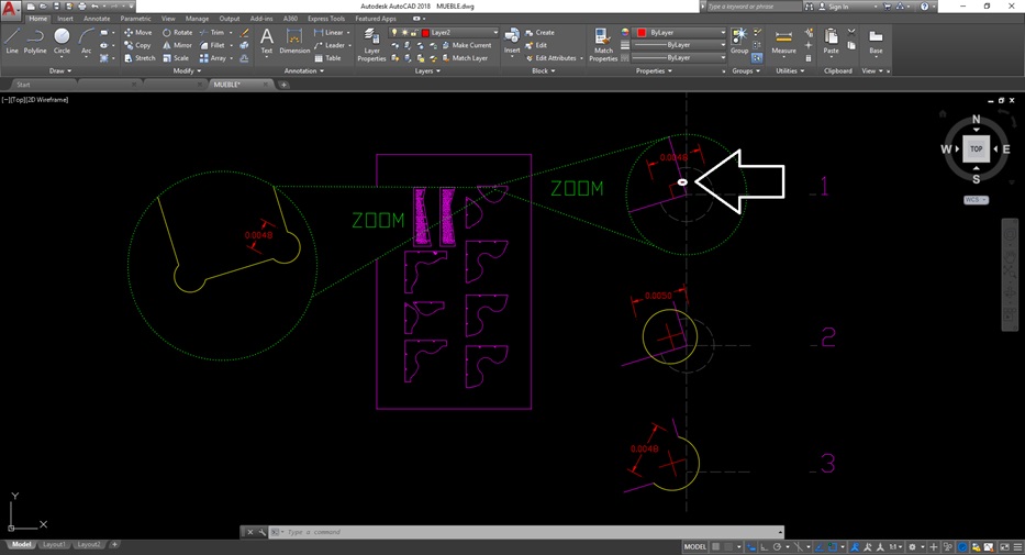 Fig.08 - Dogbones
 The 2D design ends when we order the pieces in the dimensions of the piece to be cut, in my case the MDF measures 2.00mx1.30m. Find the way to fit the pieces because at the beginning I got 2 more boards, but if it is ordered and rotated it is possible to reduce the material to be cut. Save the .dxf link in a new folder to open the file.
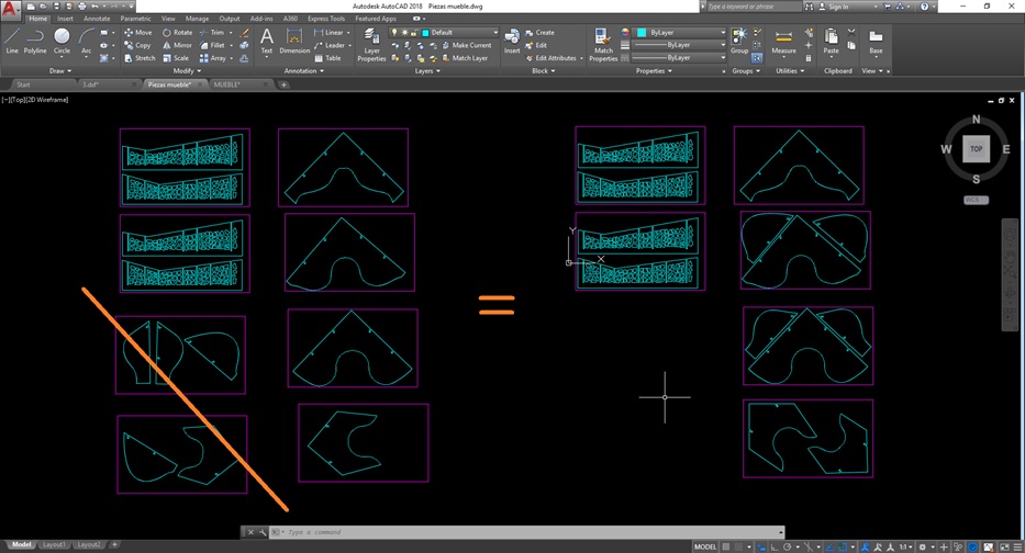
Download DXF Files
Fig.09 - DXF Files
3000 series Multicam Router CNC
The purpose of this week is to make something big on a CNC machine. At Fab Lab CIT ULIMA, we will find the 3000 series Multicam CNC Router, a machine designed for architectural carpentry applications like plastics, non-ferrous metals and composite materials.
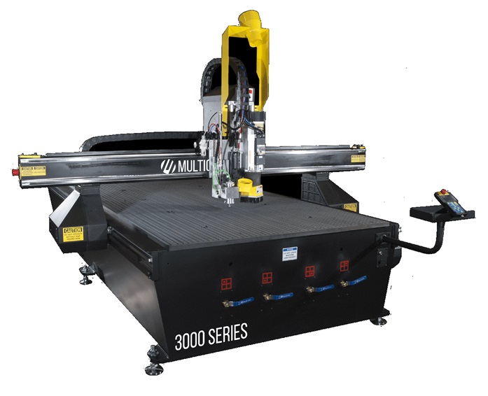 Fig.10 - 3000 series Multicam
 The specifications of the machine are as follows
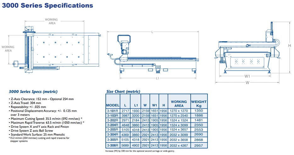 Fig.11 - 3000 Series Specifications
 The multicam router will provide years of productive service if it is mantained properly. There are daily, weekly, monthly, quarterly and yearly maintenance steps required for each machine based on a 40 hour work week.
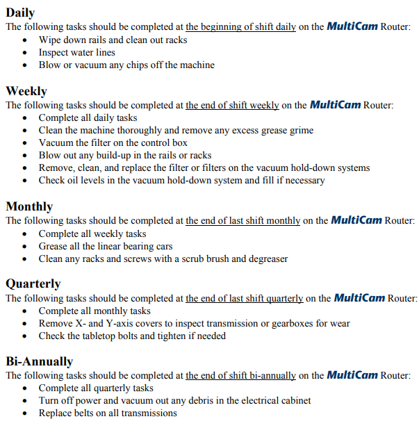 Fig.12 - Maintenance
 The CNC has characteristics and elements such as "Automatic Tool Changer (ATC)", It features a linear tool rack holder mounted at the end of the material process area. An extended frame design on the 3000 Series does not reduce the standard process area. The CNC has an automatic milling cutter which is configured when generating the G-code.
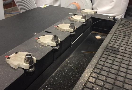 Fig.13 - ATC
 The work area is 3.0mx1.5m and the standard working surface is 1” thick 80 - 82 durometer phenolic with a grid pattern to utilize 0.5 x 0.250 foam gasket tape. The depth of the cut to be made is greater than the mdf base I will use, so I will fix it with screws in another mdf base which is held in the gridded vacuum plate of the multicam.
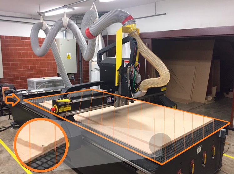 Fig.14 - Standard working and fixing surface
 It has an external component, The vacuum pump option is available with different levels of horsepower. The sales associate can help operators.
It is necessary to turn it on before sending the file to be cut, in this way we avoid residues in working surface
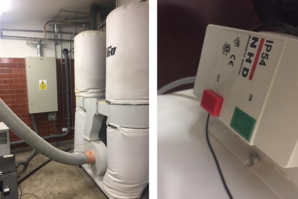 Fig.15 - Vacuum external components
 The power button is on the back, it is necessary to check that the pressure is above 80 and that the vacuum hold is on.
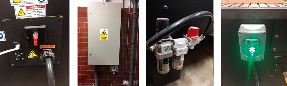 Fig.16 - Component
 The MultiCam graphic keyboard provides more flexibility to access the router by allowing the operator to be closer to the work surface and with practice it is easy to remember what each button is for.
It has an emergency button on the hand keyboard or on the side of the porch that cuts off the power. When using it, all the job configuration information will be erased from the system and you must wait at least 2 minutes before activating the machine and apply power to the motors.
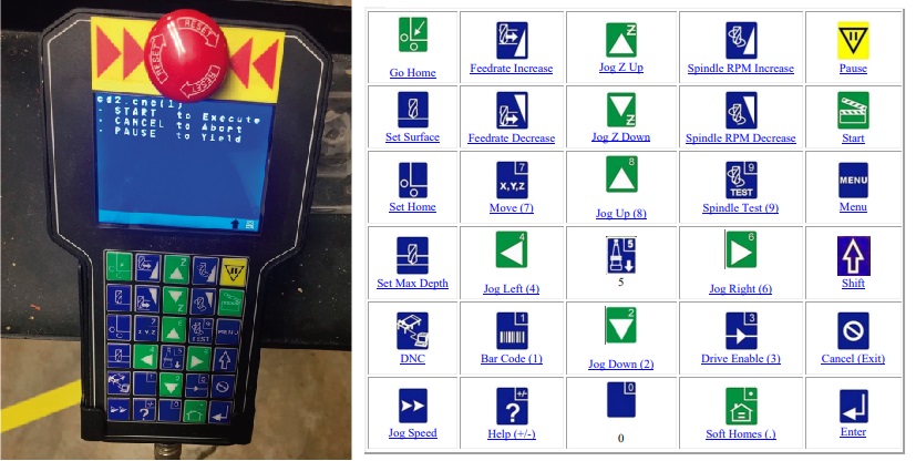 Fig.17 - Handle Keypad
 The calibration elements are connected close to the milling cutter.
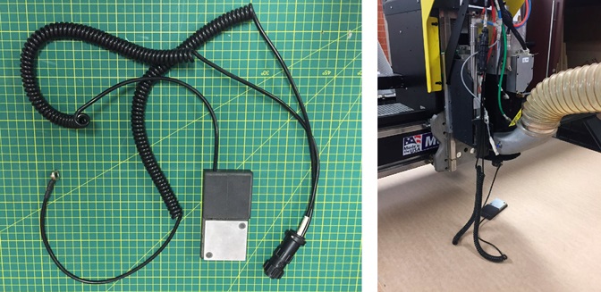 Fig.18 - The calibration elements
 To calibrate it is necessary to follow some steps.
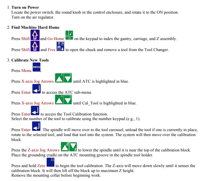 Fig.19 - Fast Start – ATC Spindle
 If you follow the correct procedure the result is applied like this.
To set the machine and leave ready to operate, you must do the following.
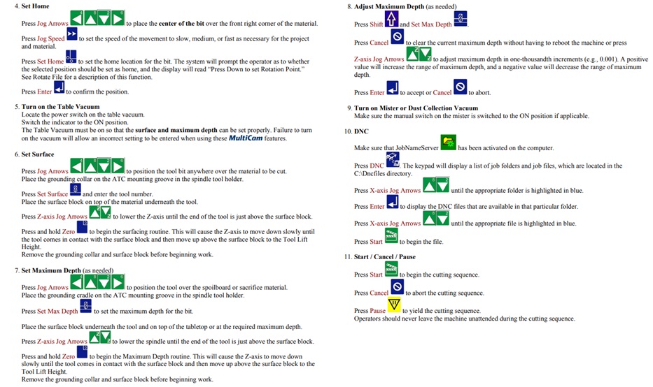 Fig.21 - Set machine
 If you follow the correct procedure, the cutter will be placed in the corner of the CNC.
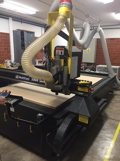 Fig.22 - Set machine
 EPP
Any person who operates or does any maintenance on this equipment should be aware safety procedures. Wear approved eye and hearing protection at all times when operating the routing system (1); avoid wearing neckties and scarves during machine operation, Wear gloves when handling sharp, hot parts and placing or removing heavy material (2); observe and follow all safety signs on the machine and in the surrounding areas (3); avoid placing hands on the tabletop when the spindle is turned on; Lock out the incoming power supply when any type of maintenance or other work is being performed on the machine. There should be extinguishers of easy accessibility, it's important to always keep the work area clean and uncluttere and finally do not to leave the machine unattended.
 Fig.23 - EPP
 CAM
The software of the multicam is called Enroute and the extensions with which I was testing were .dwg and .dfx.
First, we must define the dimensions of the plate 3000mm x 1500mm.
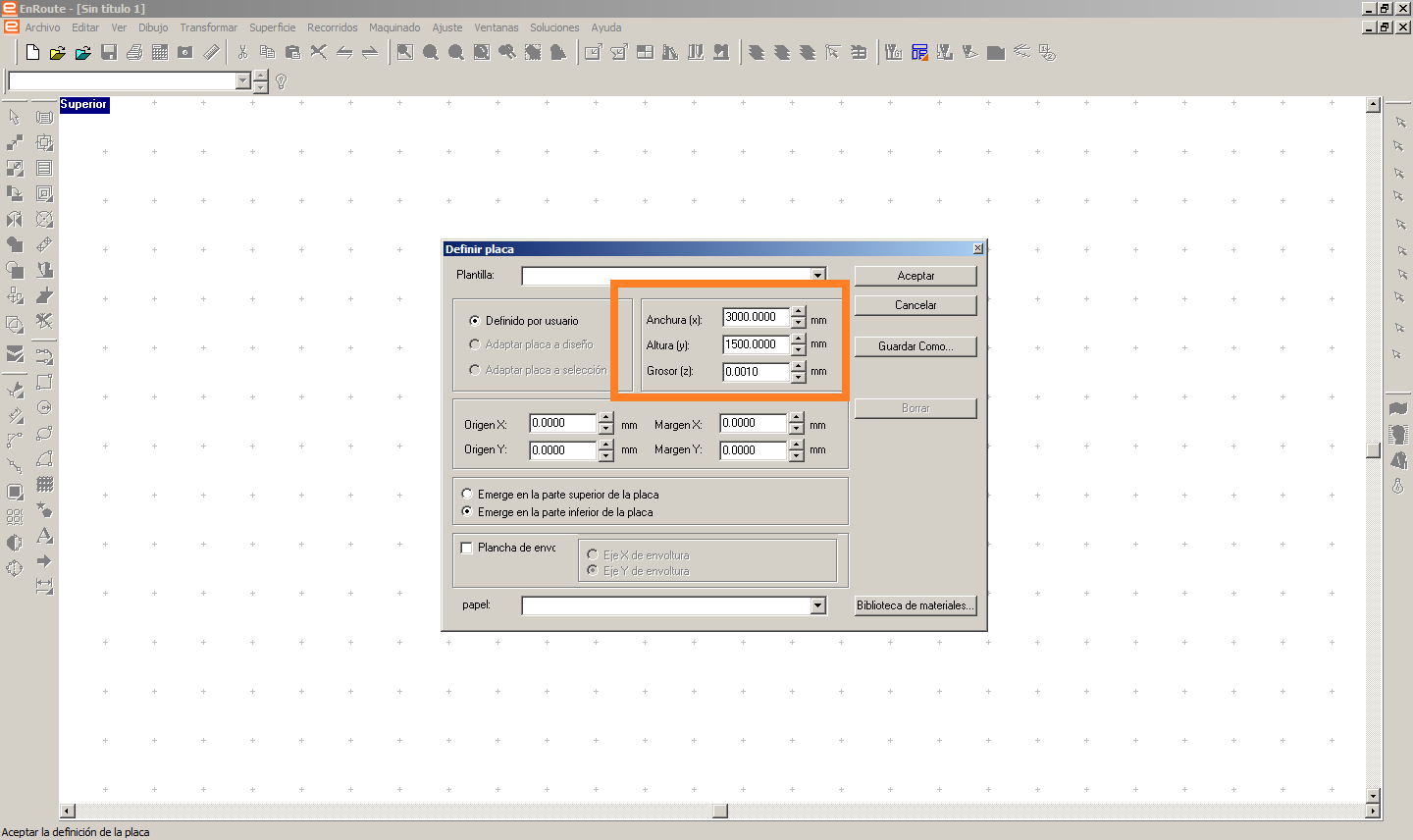 Fig.24 - EnRoute Interface
 We import the pieces to cut and we begin to place them in the established dimensions of red color that shows us the length of the work area of the CNC
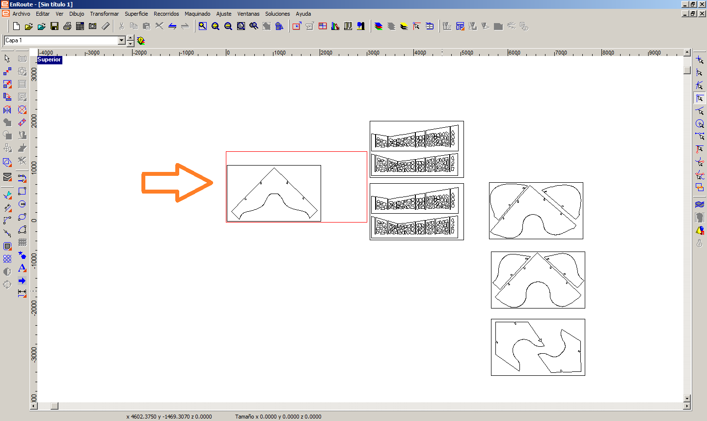 Fig.25 - Import Files
 If there are no double line problems, at the time of selecting the piece it will turn blue, if it fails, it will be magenta.
Then, we open the displaced router. We selected the mill to use, in my case I will use the 3/16" end mill setting and the external axis cut.
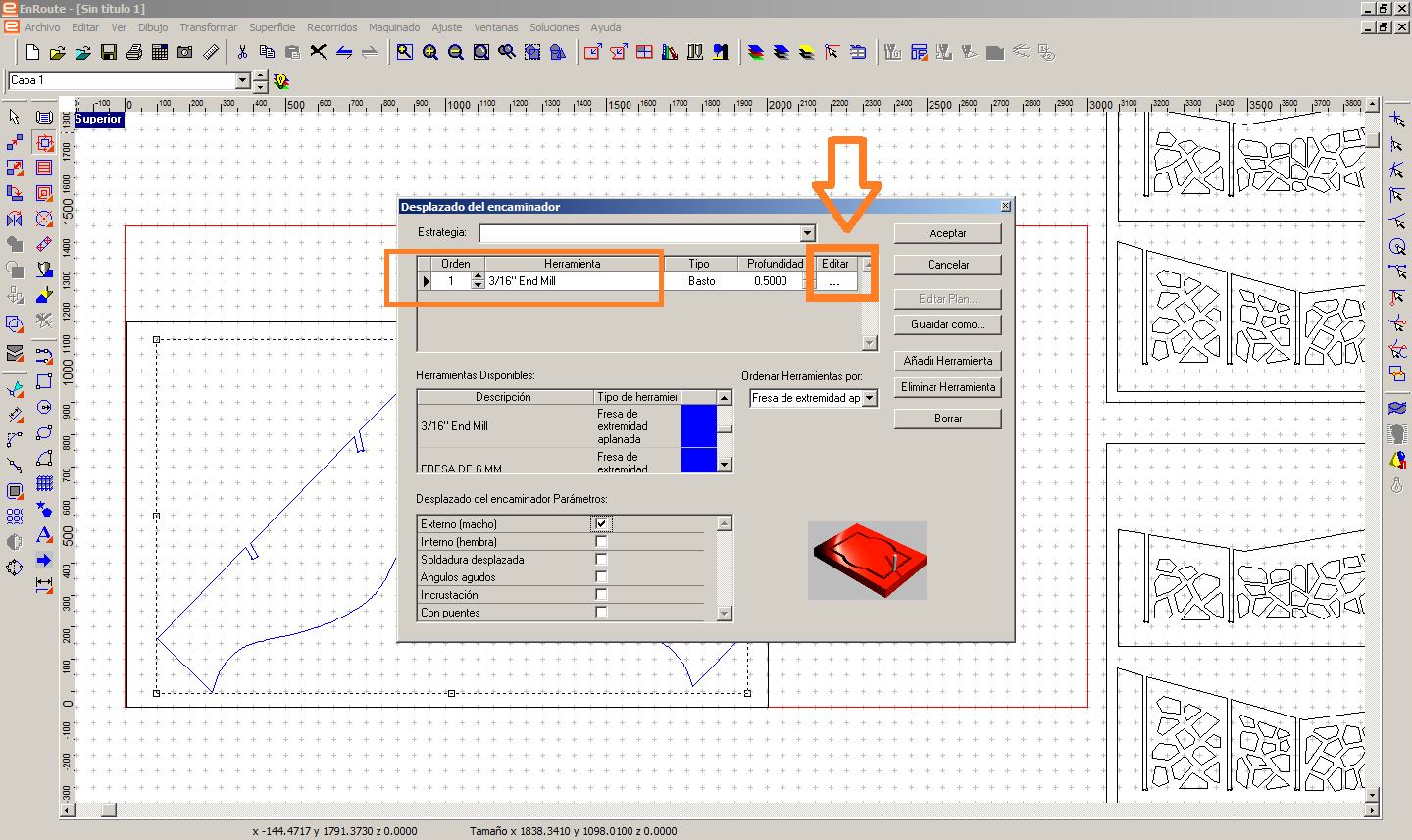 Fig.26 - Mill Select
 We configure the depths according to the material, the passes, the feeding and the speed. We verify the type of cut if it external or internal since that defines if the cut passes inside or outside the design axis of the piece.
In this case we set the depth of cut to 12.8mm for the horizontal pieces that will be cut in MDF of 12.3mm. Also, we selected a feed speed of 400mm/min, 3 number of passes and spindle speed axis of 18000 rpm. On the other hand, for the vertical pieces, the parameters were the following: the number of passes (3), feed speed (800mm/min) and spindle speed (18000 RPM).
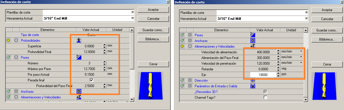 Fig.27 - Mill cut setting
 We click on the "G-code" tool to generate a new file.
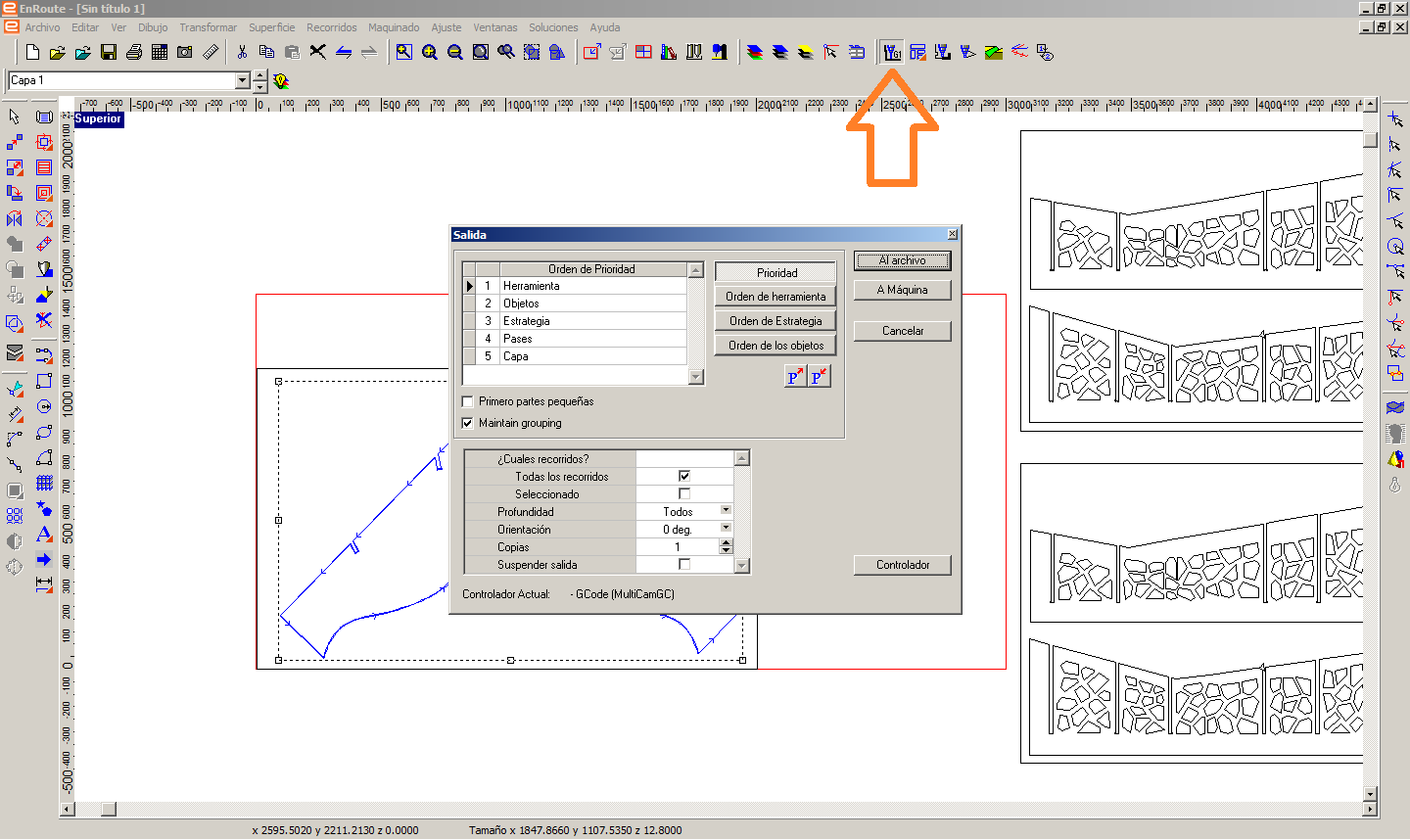 Fig.28 - G-code
 The G-code is generated in a file of notes, in this we ensure that the drill is in the correct spacer. In my case in T1.
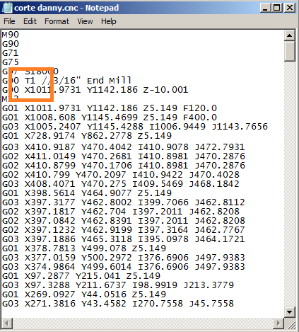 Fig.29 - G-code Notepad
 We open the JobConsole program, it shows us the G-code and we are ready to send the file.
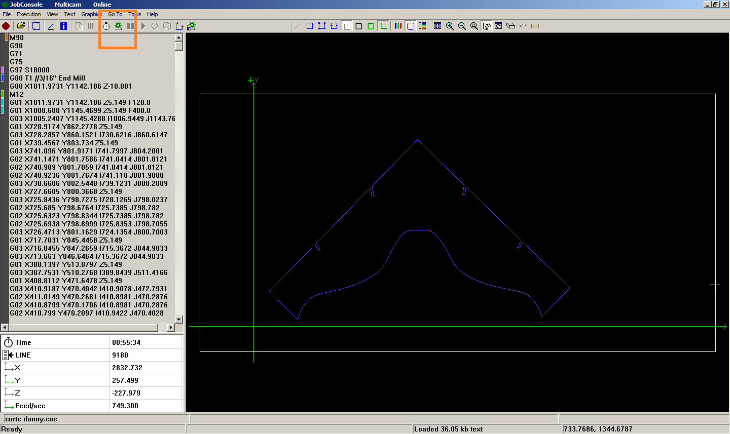 Fig.30 - Ready to start
 It is suggested not to use an empty work surface, a wooden base will be placed to absorb the damage by the milling cutter if it exceeds the drilling surface. I will use MDF material since it does not need a sanding process as opposed to using plywood; however, our MDF plate will be screwed in so that it does not move, since our iron is on the work surface.
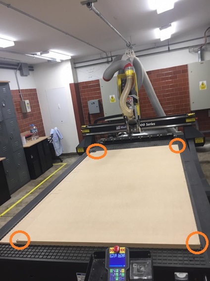 Fig.31 - Suggestions Fixing work surface
 After securing our material, select the start button and the cutting process will look like this on the computer screen.
For the design of the voronoi the mill was chosen to perform the internal design axis cut, in this way we generate less area and greater structural support between the branches of the voronoi geometry.
For the design of the outer cut, the cutter was chosen to make the external design axis cut, in this way we do not modify the measures of computer design.
ASSEMBLY
Using MDF, the sanding process was almost nil.
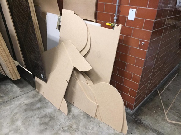 Fig.35 - MDF parts
 It is necessary to increase the precision when creating a 2D/3D design of the three-digit file, for example the MDF it used was 12,560mm but the program changed and showed a new measure of 13.00mm. So there was no need to make an extra cut or sanding to assemble the furniture.
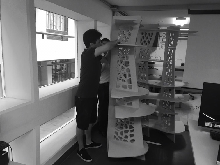 Fig.36 - Suggestion
 Fab Lab CIT-Ulima
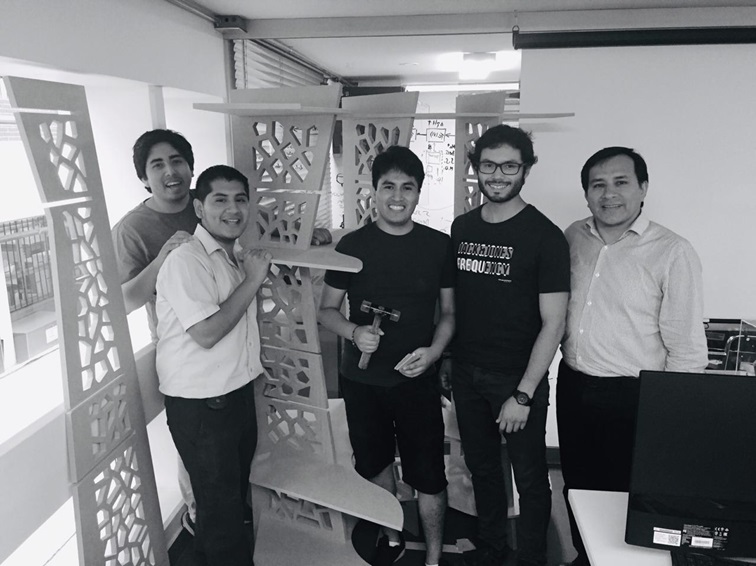 Fig.37 - CIT Team
 As it was raised in the 3D model, the result was amazing.
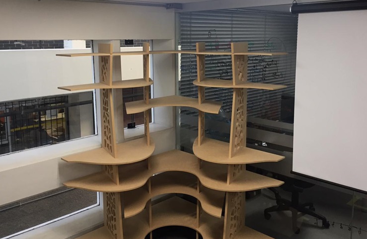 Fig.38 - furniture
 I accommodated our previous designs in the furniture created in the CNC
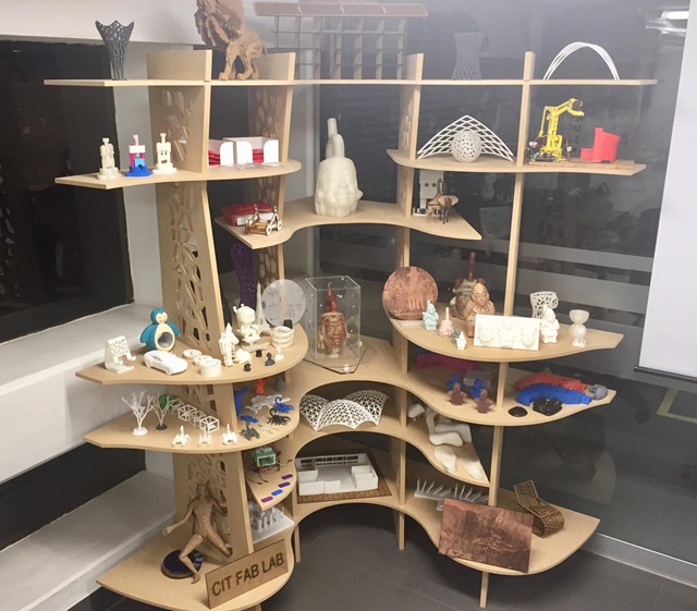 Fig.39 - Hero Shot
 Group assignment
In our laboratory we have the CNC Multicam 3000 series router, our first test was to test the two types of trajectory executed by the CNC mill as the external and internal axis cut trajectory. Both execute the cut outside the axis of the modeling line. That is, in the example we can see that the internal part can never pass through the hole in the hoop. Even if both have been designed in the same plane and have the same axis cutting. The cut parameters are the number of passes (1), feed speed (800mm/min) and spindle speed (12000 RPM).
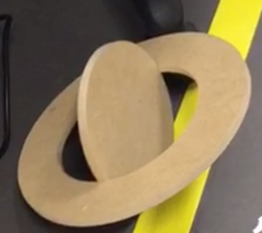 Fig.40 - Trajectory
 Before making the details of the relief corner: Dogbones, we followed the suggestion of our local instructor. The CNC can generate a continuous cut if we contemplate the design "the length of the cutting corner".
In our test we use the 3/16 "bit, so we leave a space of 4.9mm and effectively the cutter produces a continuous cut and is seen in the photo. If the Hole of the Dogbones have a lower measurement it is recommended to create the holes first and then make the cut. The cut parameters are the number of passes (2), feed speed (600mm/min) and spindle speed (12000 RPM).
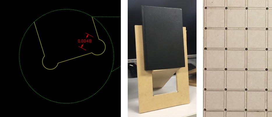 Fig.41 - Dogbones
 On the other hand, we try to create a kerf pattern that turns to one side of the vertical axis, we will try it in the 18mm plywood material. However, we omitted the intermediate design of the geometry and when testing it it broke. The cut parameters are the number of passes (3), feed speed (600mm/min) and spindle speed (18000 RPM).
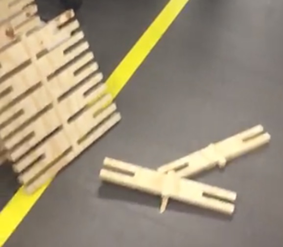 Fig.42 - Kerf pattern 1
 We tried another kerf design with a higher speed to the previous test, it was observed that the more speed is increased at the cut, it produces more waste on the surface. The cut parameters are the number of passes (3), feed speed (400mm/min) and spindle speed (18000 RPM).
Due to the anisotropic characteristics of the wood, the material that was subtracted perpendicular to the main direction of the test does not compromise the overall structural capacity. In this way, it achieves a curve that exceeds our expectations.
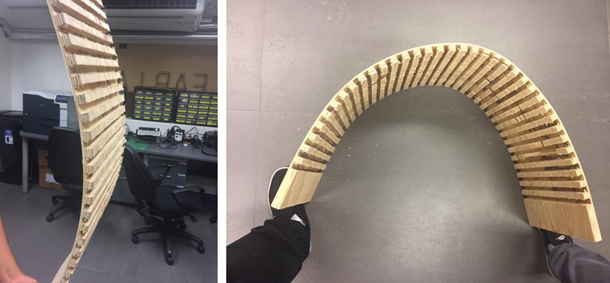 Fig.43 - Kerf pattern 2
 To see all the documentation of the group work, you can visit the CIT page.