Week 06: 3D Scanning and Printing
This week we will identify the advantages and limitations of scanning and 3D printing technology. We will apply design methods and production processes to demonstrate your understanding.
Individual assignment
3D Scanning
A 3D scanner is a device that analyzes an object or a scene to gather data of its shape and occasionally its color. The information obtained can be used to build three-dimensional digital models that are used in a wide variety of applications. In the laboratory of Fab Lab CIT ULima we will find the Creaform HandyScan 700.
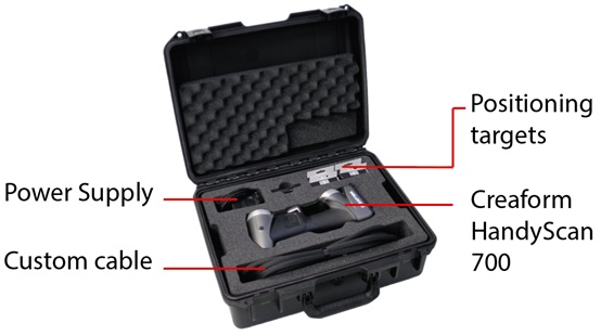 Fig.01 - Creaform HandyScan 700
 I learned the applications of the Creaform machine from CIT Ulima, these are intended for the following activities: Museology / heritage conservation; Conservation, restoration and digital archiving; 3D digitization for research, analysis and publications; finally, Multimedia and entertainment. I will share some pictures of some projects of the CIT FAB LAB ULIMA.
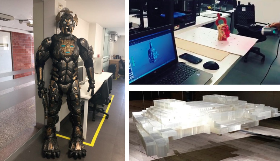 Fig.02 - CIT Ulima Projects
 I learned the functionality of the scanner, as a first step it is necessary to calibrate it. Changes in the environment may affect the scanner calibration, mostly due to pressure or temperature variations. Optimizing the calibration allows you to get back to the initial measuring characteristics.
The software interface can be operated from the computer or from the Creaform HandyScan.
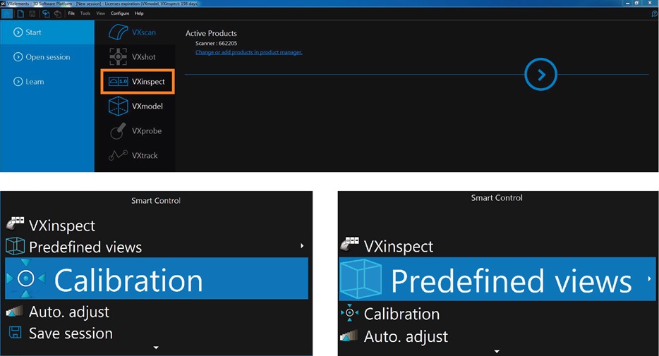 Fig.03 - VXelements Interface
 VXelements includes an application to optimize the calibration of the scanner by clicking on Calibration of the scanner in the main toolbar.
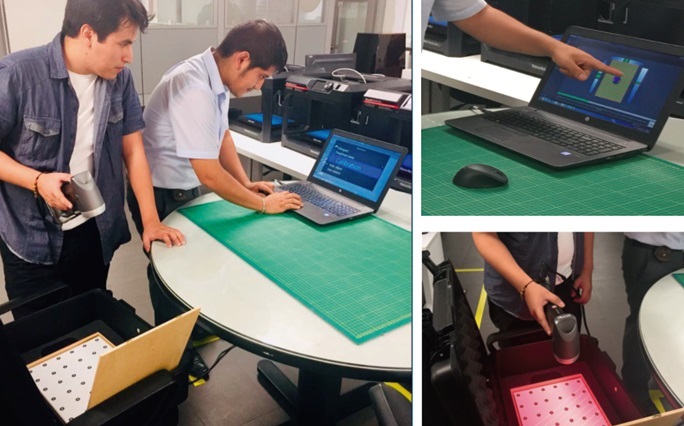 Fig.04 - The calibration
 The calibration uses a known reference, the calibration plate, and consists of bringing the scanner to fourteen positions represented by the three green indicators. The process ends when a window appears indicating that the process is optimal.
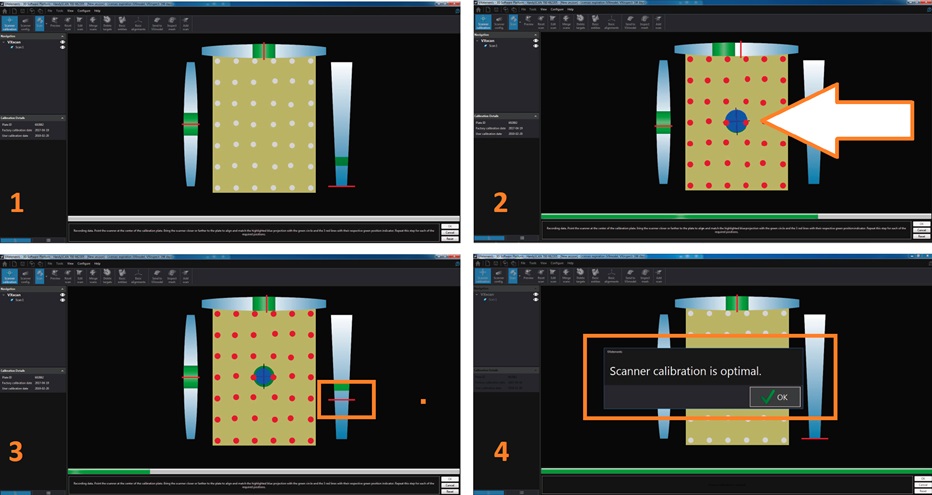 Fig.05 - VXelements Interface
 The next step is to scan the target positions, when passing the scanner by the location of each one it will appear in red color (2), in case we need more we add them with the scan parameters tool (3). At the end of the process it will show us the exact amount of the target used (4).
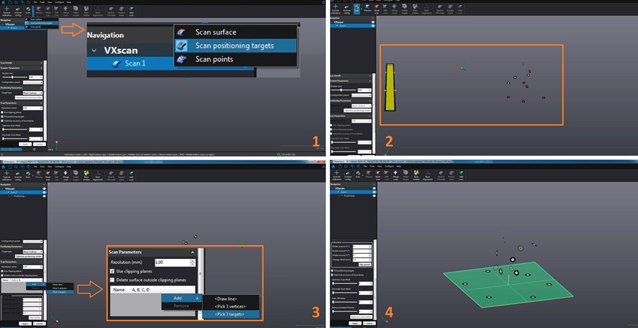 Fig.06 - Target
 The next step is to place the positioning targets on the object to be scanned, these are essential to create a reference point for the 3D scanner that allows users to register all the frames of the design. In this opportunity to use the HandScan I chose a vinyl figure with complex geometries, since I wanted to increase the difficulty when scanning an object.
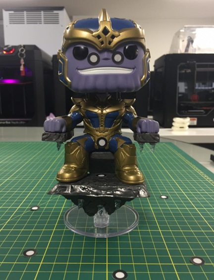 Fig.07 - Positioning Targets
 The scanning process shows us the design in real time on the laptop, so we will see if any part of the object is missing to be scanned.
I decided to scan a complex object to know the solutions that could be generated in the process. So, I observed that my object was not complete, I needed to scan horizontally to get the full scan.
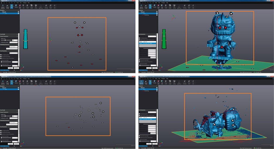 Fig.08 - Suggestion
 When generating two scanning processes in the same file, we need to merge them. To do this, we select union points, these have to be the same in both scanned images, which will be selected manually.
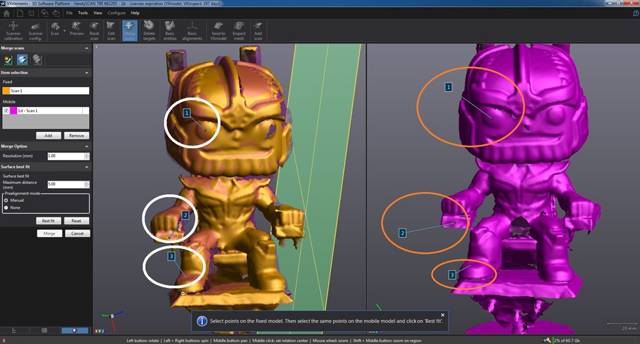 Fig.09 - Merge Option
 Once the fusion is complete, the scanned file could be printed or retouched with other 3D modeling programs.
 Fig.10 - New merged object
 3D printing
3D printing is a group of manufacturing technologies by addition where a three-dimensional object is created by superimposing successive layers of material. Thus, the scanned object will pass through the 3D printing process.
Previously, I worked with projects printed in 3D and I had the opportunity to use several printers from the makerbot and stratasis range, which I will explain in detail in the group assigment.
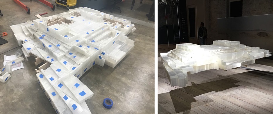 Fig.11 - "En Reserva", pavilion of Peru at the Venice Biennale 2018.
 Once you scan the object, you need to pass the 3d modeling process. I will use the rhinoceros program to treat complex geometries; However, Jaime Sueno our Technician and Lab Assistant taught us the parameters of the geomagic free form program, an advanced software that allows to modify meshes with the option of sculpting. In comparison to rhino, this program reduces working time considerably.
 Download STL file
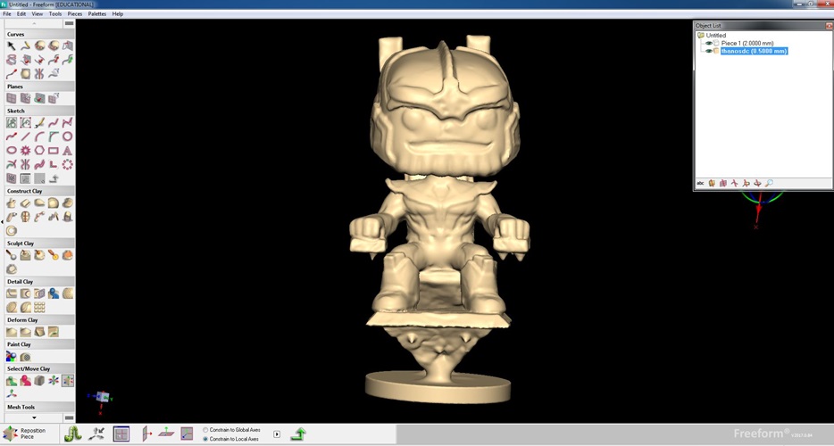
 Fig.12 - Geomagic Freeform Interface
First of all, to complete the 3D printing process it is necessary to have the object to be printed in the .obj or .stl format, then insert it in the software of the printers. In this case I will use the makerbot 2x printer, since the group assigment notes that the 2x has a better finish than the makerbot 2 or the makerbot plus.
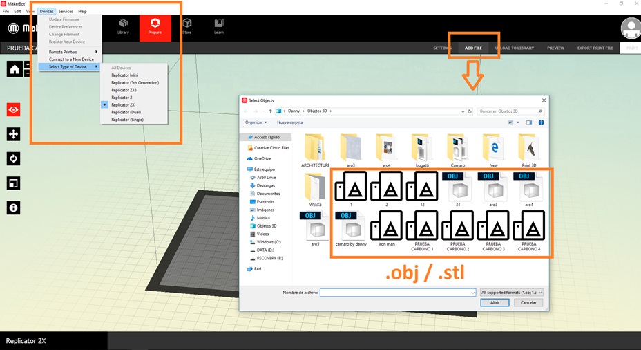 Fig.13 - MakerBot 2x Interface
 Normally the parameters of the makerbot 2x printer are left by default. In this case, I will use the standard quality, I will add raft, support.
If we move something by mistake the software will show us a symbol *, the only solution would be to click on "Restore Defaults". I will use the quick setting, the default parameters and activate the support option.
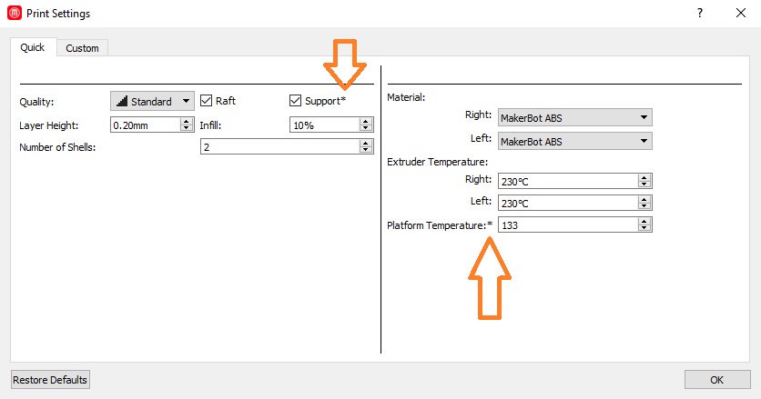 Fig.14 - Print Settings
 In the print preview, we will observe the printing time and the amount of material to be used. The option to print or export will appear in the window.
If a piece modeled in 3d is not closed, the preview setting will show an opening or a deformation as in the image. If we send it to print, it will leave openings.
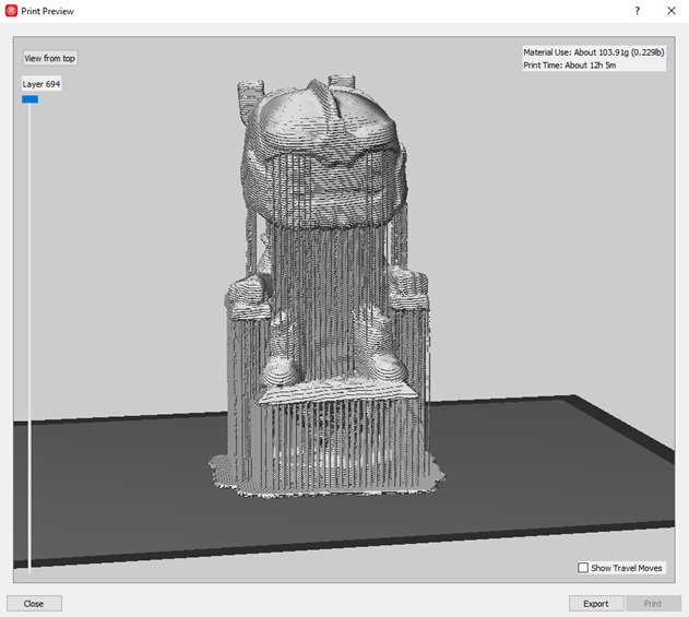 Fig.15 - Print Preview
 This is how the makerbot machine prints
The final result of the 3d scan is a small piece of 15x8x8 cm, a disadvantage of the manufacture of additives is that the parts often do not have the heat resistance or surface finish required for the final finish.
Our design could not be done in a subtractive way since the funko shape implies openings between the body, the head and the support base. However, there are machines that have more than three axes that could allow the desired finish in the design of the funko from a subtractive manufacturing such as the Kitamura CNC.
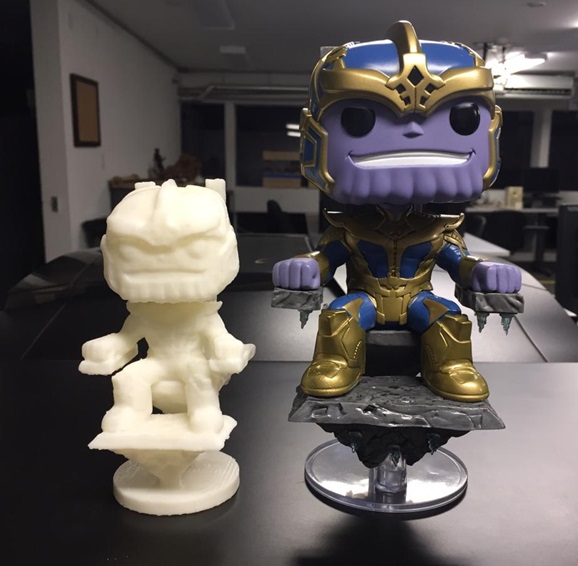 Fig.17 - Additive & Subtractive Manufacturing
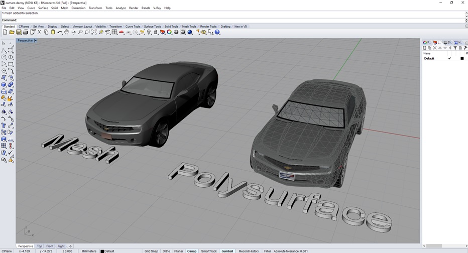
 My second test was to import an object mesh in 3D, i downloaded a shell of a Camaro. The meshes can not be worked with the addition of geometries; therefore, with the MeshToNurb command, i changed the mesh format to polysurface.
When having a polysurface, work on the thickness of the impression with the OffsetSurface command, this will avoid errors when printing.
 Download Camaro Mesh File
 Download STL
Fig.18 - MeshToNurb
When finishing 3d modeling, export it in .stl format. For this impression I will try the makertbot plus, I will use the default configuration and with the preview tool I can see the amount of material (124.48g) and printing time (About 21h 27m).
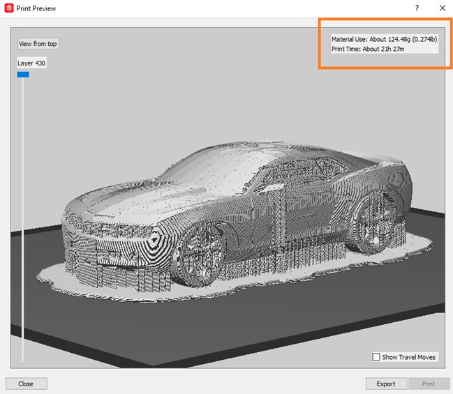 Fig.19 - Print Fails
 I consulted with my local instructor, Alejandro Otazú, about the data obtained and he gave me some recommendations such as reducing the amount of infill density, raft margin and support density. These modified parameters are the following: support (.10), raft (4mm) and infill 5%.
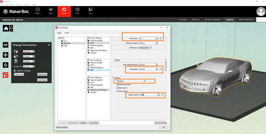 Fig.20 - Decrease Printing Time
 Following the recommendations I realized that the change is radical, the 21 hours of printing were reduced to 6 hours. The amount of material is also considerably reduced and this is notorious if you want to print 10 or 100 times the same design.
I forgot to give offset to the windshield and the preview setting indicated an opening or a deformation as in the image. If we send it to print, it will leave openings. In order for the machine to start the printing process, we click on Print.
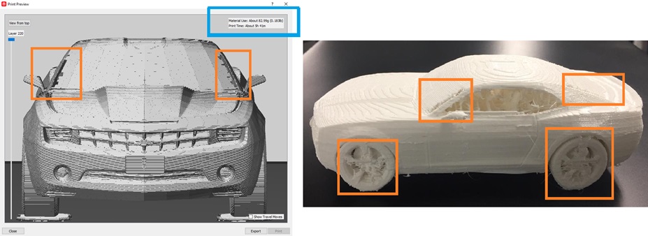 Fig.21 - 3D Print Suggestions
 The last step was to clean the supports and the raft of the impression, the result is a single printed piece of PLA
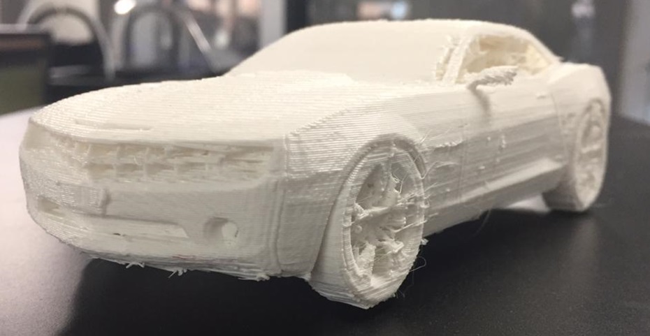 Fig.22 - Camaro 3D
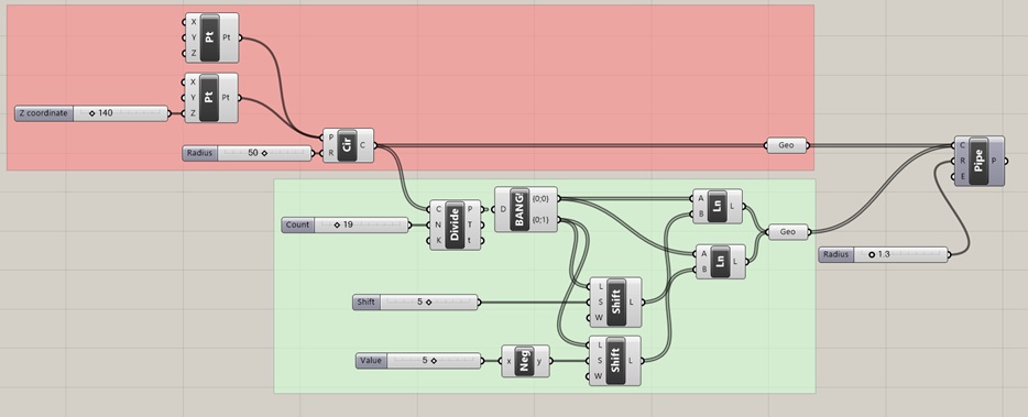
 My third test is to create a basket in the grasshopper program by means of dispersed joints that vary between two circles
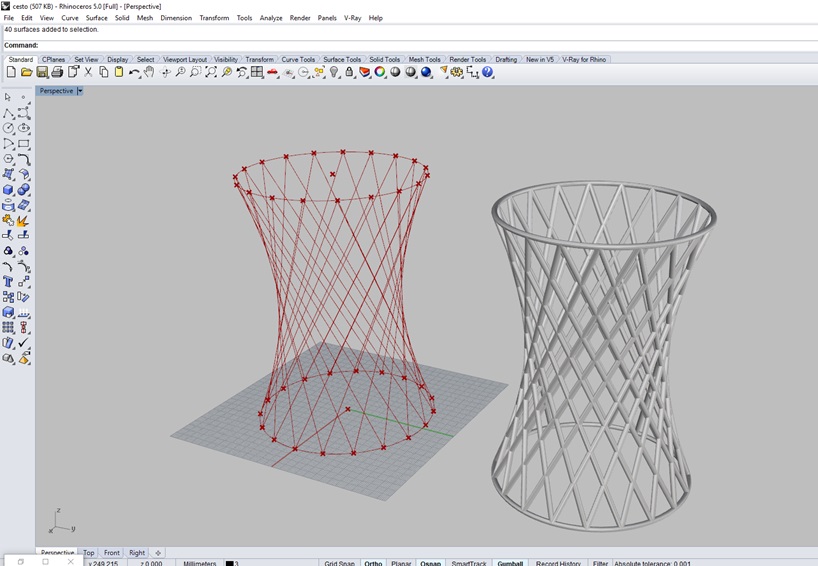 Fig.23 - Basket Case
 To do this, I group the domains that create the geometries, on the one hand, how to create distance between two circles and how to divide these into several interlacing points. To open the file it is only necessary to drag the download to the grasshopper window and to generate the geometry just use the grasshopper "bake" tool.
Download Basket Case Grasshopper File
Download Basket Case STL
Fig.24 - Download BasketCase Files
Being a double curvature geometry, this could generate support according to the dimensions of the joints. In this test there was no need to create support, I just think raft. The parameters established by "Quick" settings were used: support (.20), raft (4mm) and infill 10%.
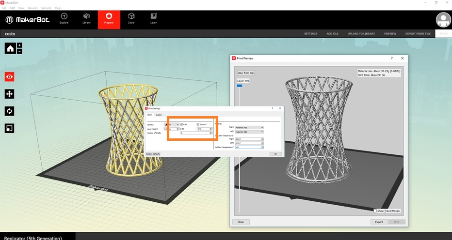 Fig.25 - Makerbot Interface
 The test was sent to print with the maker of the replicator + printer and the new filament called tough was used, which has greater resistance.
In the test we can see that it has not generated any support, this is because the dimensions of the joints are greater than the size of the extruder of the printer
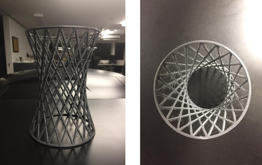 Fig.26 - Test
 My fourth test is to create a type of column that responds to the gravity loads, for this I will create lines that form a triangular geometry in the base, and I will project it in the inverted cone type solid.
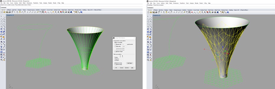 Fig.27 - Parametric column
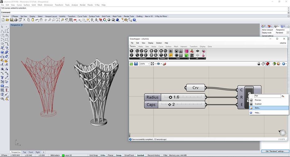
 After generating projected lines, I had to generate thickness in the design. However, I was going to delay generating pipes in rhinoceros so I decided to submit the test to the grasshopper pluggin to create them with a click. It was considered a radius of 1.6 and a type 2 enclosure (circular).
Download Column Grasshopper File
Download Column Rhinoceros File
Download Column STL
Fig.28 - Parametric column + grasshopper
We make sure that the diameter of the joints is greater than the nozzle of the extruder and we confirm in the makerbot software that it does not create support. The parameters established by "Quick" settings were used: support (.20), raft (4mm) and infill 20%.
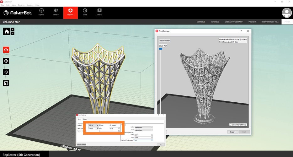 Fig.29 - Suggestions
 The final result does not consider support in its printing, which saves us time and material.
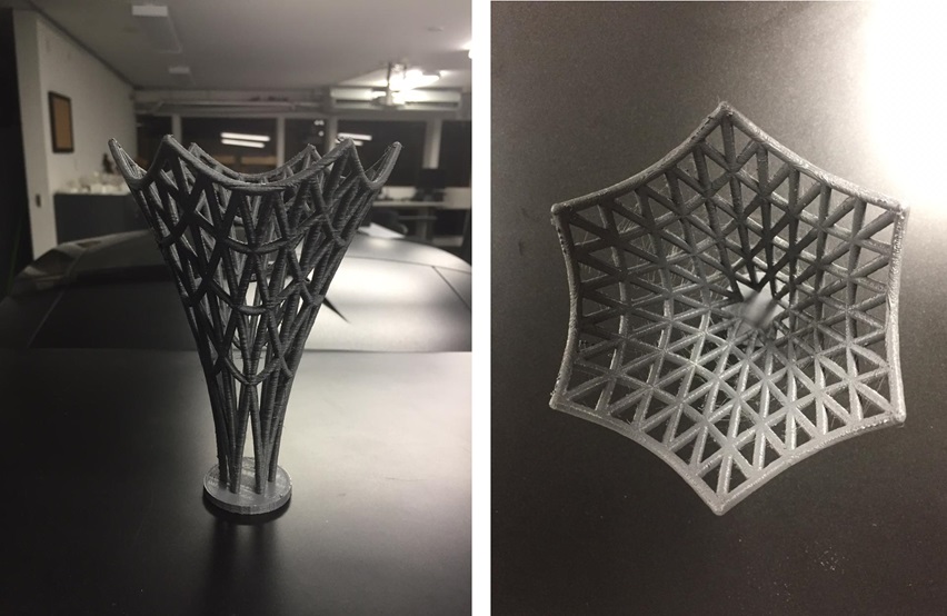 Fig.30 - Test
 Group assignment
In our group assignment, we have tested all laboratory printers of the fablab CIT Ulima as the following: Makerbot replicator 2, replicator 2x, Replicator +, Markforged, Nobel XYZ. We managed to identify the characteristics and problems we had with each of them. They all work with the extensions of stl, obj, thing. We will attach some printing parameters.
Makerbot parameters
For all impressions in the makerbot range, the following custom parameters were used:
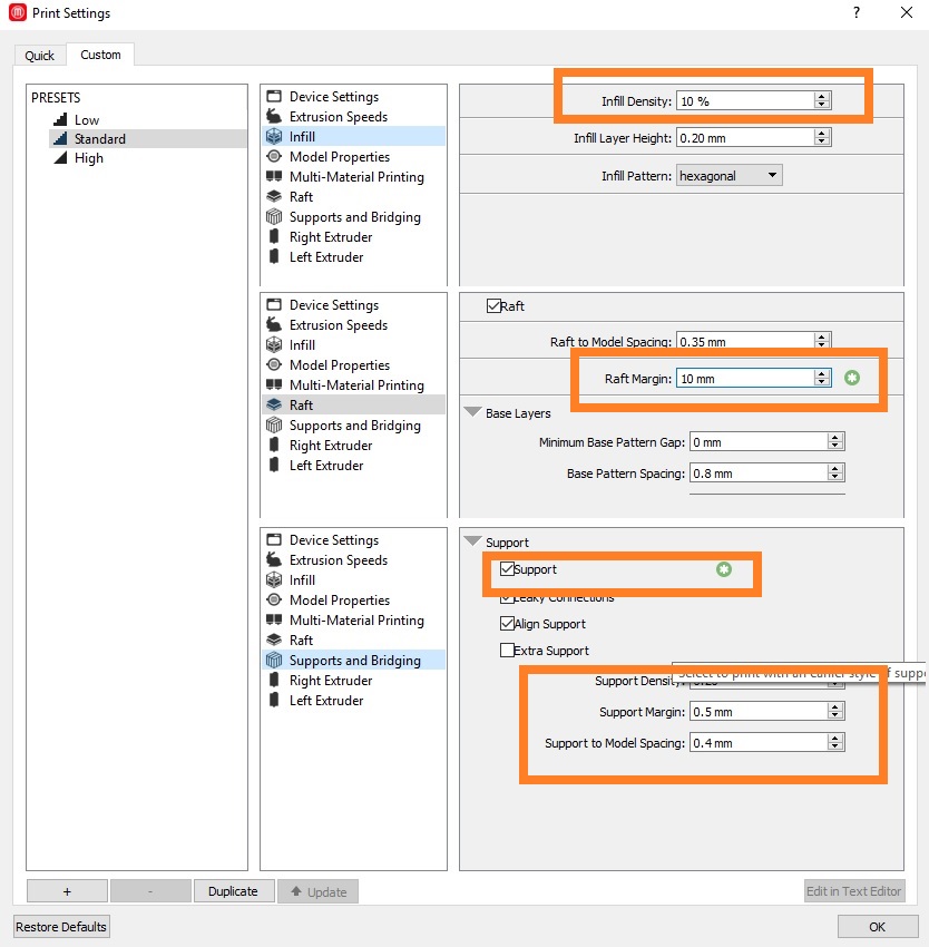 Fig.31 - Makerbot Settings
 Makerbot Replicator 2
It is Makerbot's fourth generation printer, works with operating systems such as: Windows 7/8 +, Mac OS X 10.6+, Ubuntu Linux 10.10+. The working material is the PLA filament.
Of all the printers the raft that generates is the most tedious to remove. Calibration can take a few minutes and usually you have to repeat the process since you need to practice a couple of times.
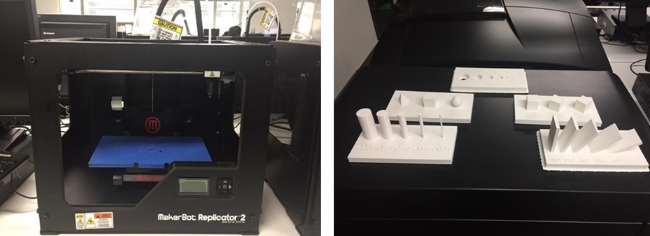 Fig.32 - Replicator 2
 The maximum degree of inclination without support is 25°, the minimum thickness that can generate is 2.5mm with perfect vertical extrusion and the spherical models have a good resolution
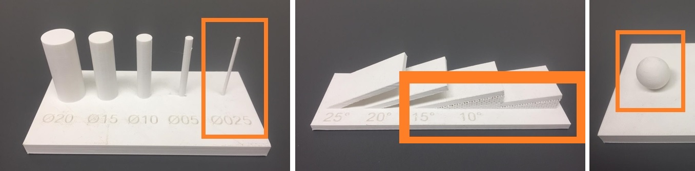 Fig.33 - Makerbot Settings
 Makerbot Replicator 2x
It is the double extruder printer capable of creating complex designs with intricate or interior supports using the soluble support material. The work material is ABS so it has a lid and a camera that needs 133 degrees to generate an adequate job. The raft and support is one of the easiest to remove.
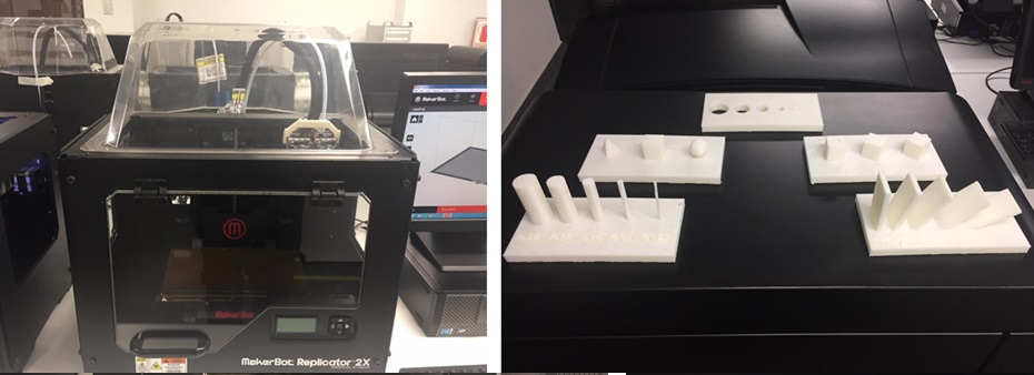 Fig.34 - Replicator 2x
 It has allowed us to create designs with an inclination of up to 25 ° without support, but in the minimum vertical extrusion has not managed to create a thickness of 2.5 mm. breaking at the top. It does not have a good resolution when creating spherical volumes.
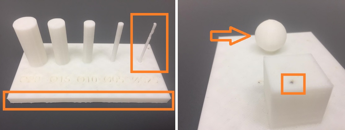 Fig.35 - Makerbot Settings
 Makerbot Replicator +
The MakerBot Replicator + prints 30% faster than its predecessor and offers a compilation volume 25% larger. The advantage is that it has more printing area and calibrate this printer is simple, only follow instructions set by the software.
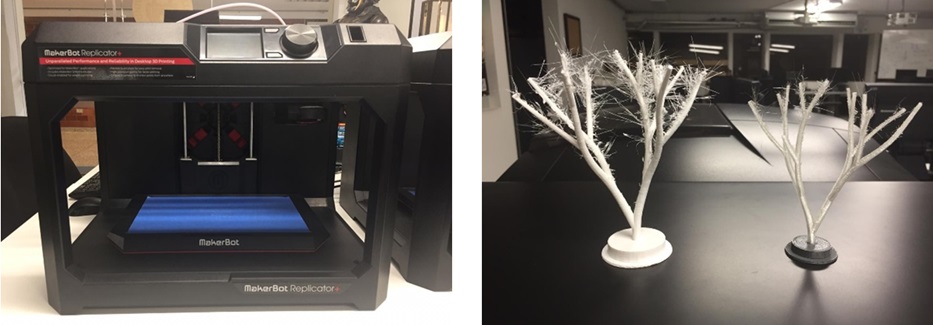 Fig.36 - Replicator +
 We test the different types of extruders like the tough and experimental. Both materials of the Makerbot brand, both have an increase in relation to speed. The tough has a greater rigidity and provides better design in curvatures, it was tedious to remove the support of the designs.
On the other hand, the experimental allows to create flexible designs the support adheres to the printed object should be removed with caution, however, you must achieve a certain configuration for each material to use when changing the nozzles of the extruder. In our samples we used the Tough PLA filament for the Tough and Nylon extruder for the experimental extruder.
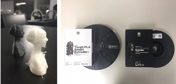 Fig.37 - Extrusors Replicator +
 Makerbot Replicator z18
The z18 printer makes models and prototypes of large concepts thanks to the working dimension that has 30.0 L x 30.5 W x 45.7 H CM. Work with the operating systems such as Windows (7, 10) and Mac OS X (10.9+).
By having a large work table, we made a triangulated coverage of 4 independent modules of 25x25cm and we saved support material which could be created in another printer of smaller size.
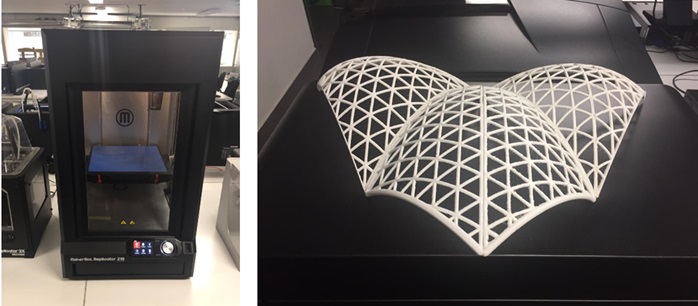 Fig.38 - Replicator z18
 To see all the documentation of the group work, you can visit the CIT page.