5. Electronics production
This week I worked on defining my final project idea and started to getting used to the documentation process.
Fab Modules
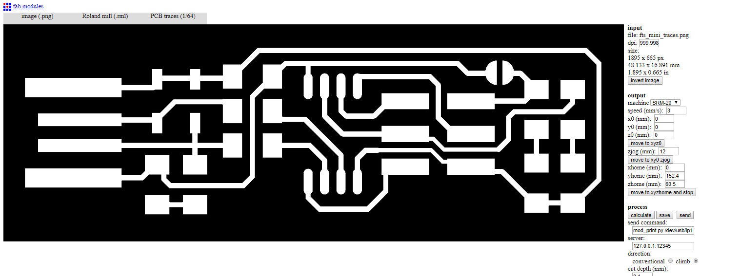
We have used Roland Modela (SRM-20) for this week assignment. We opened the image for testing in Fab Modules and went through the steps in this Tutorial.
Steps:
- Input format - PNG - select your traces image
- Output format - roland mill (.rml)
- Process - PCB traces (1/64)
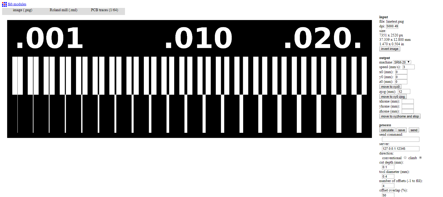
The settings on the right side:
- Machine - SRM-20
- x0(mm) - 0
- y0(mm) - 0
- z0(mm) - 0
- zjopg - 12
- Speed - 4 or 3 mm/s for new end mills
Click “calculate”
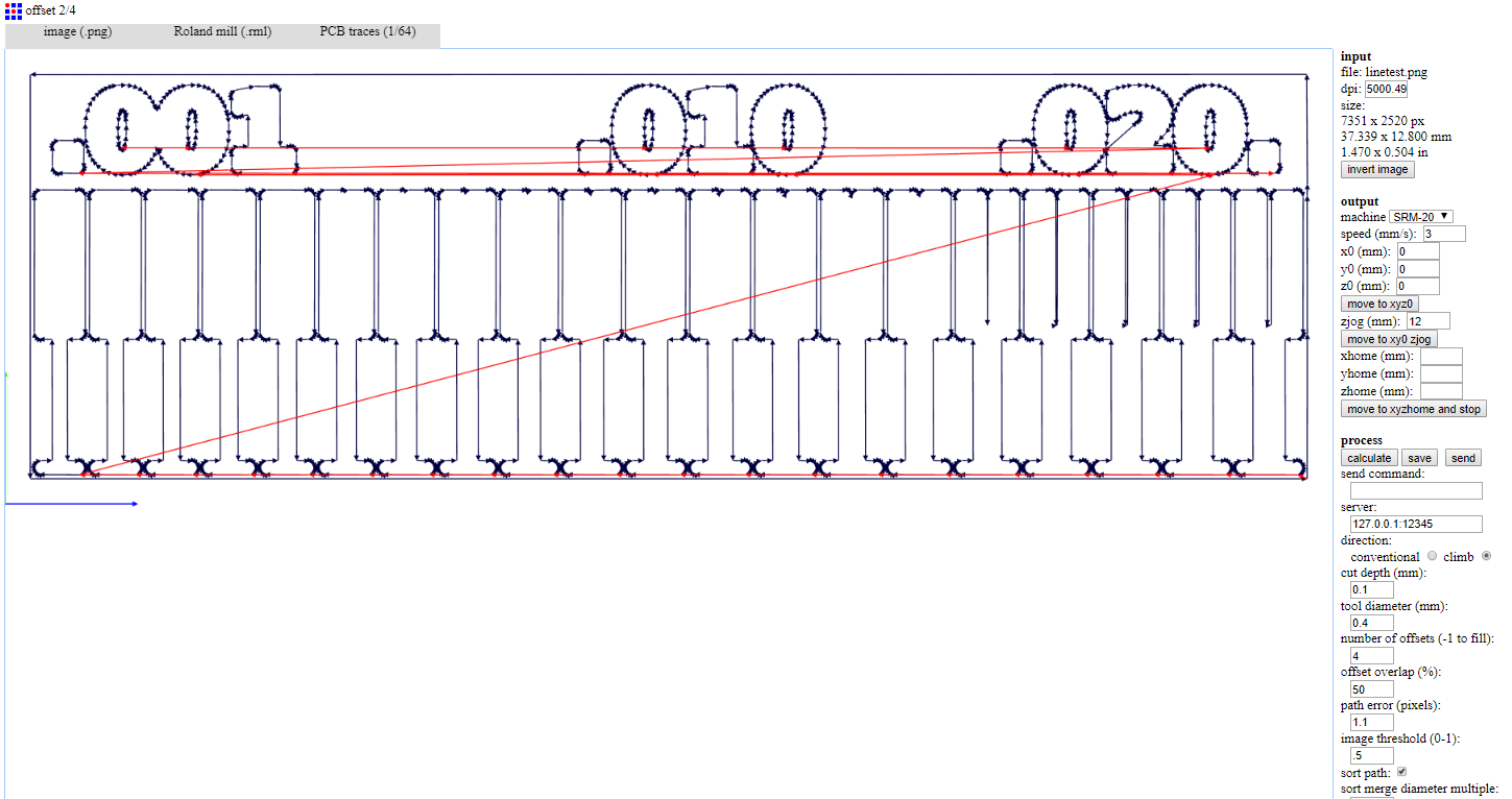
Then “save”
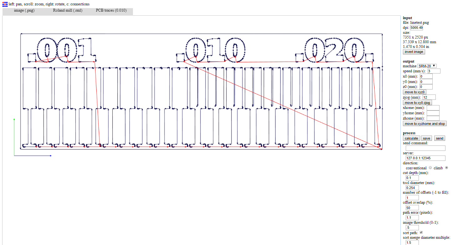
We tried to do calculate with diffrent bit sizes to see the difference
We followed the same steps to make our PCBs.
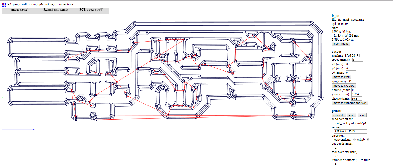
Download rml file (right click + Save link as)
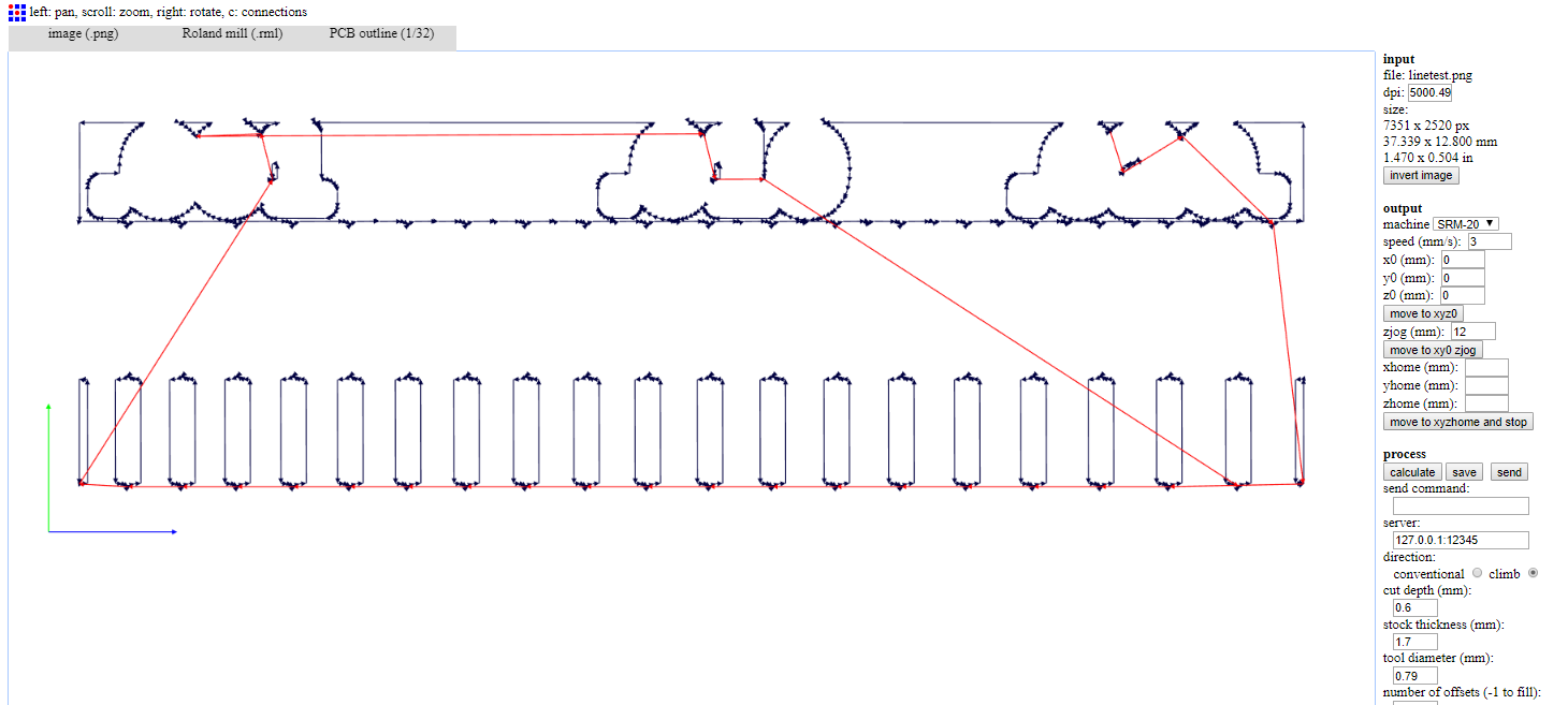
& these are the steps for the outline
- input format - PNG - select your traces image
- output format - roland mill (.rml)
- process - PCB outline (1/32)
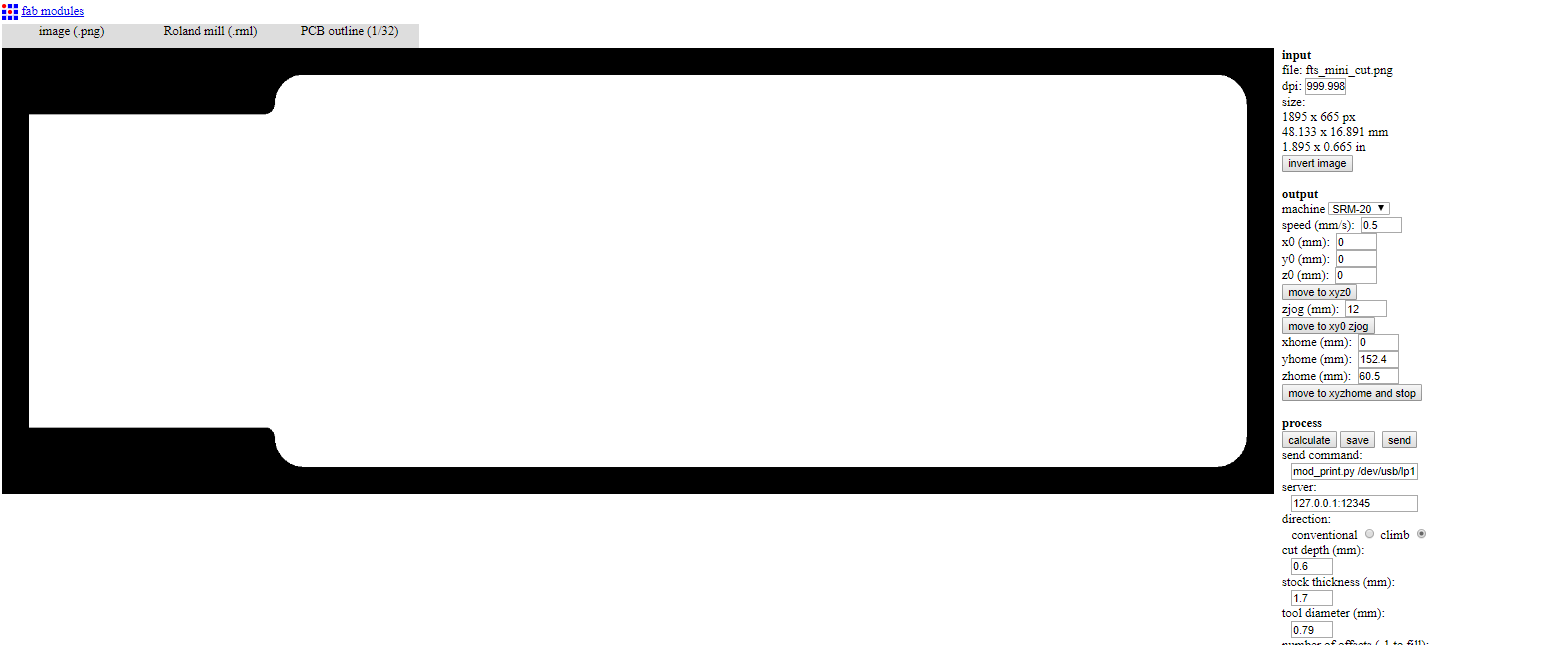
Settings:
- Machine - SRM-20
- x0(mm) - 0
- y0(mm) - 0
- z0(mm) - 0
- zjopg - 12
- Speed - 0.5
Then clicking “calculate” & “save”
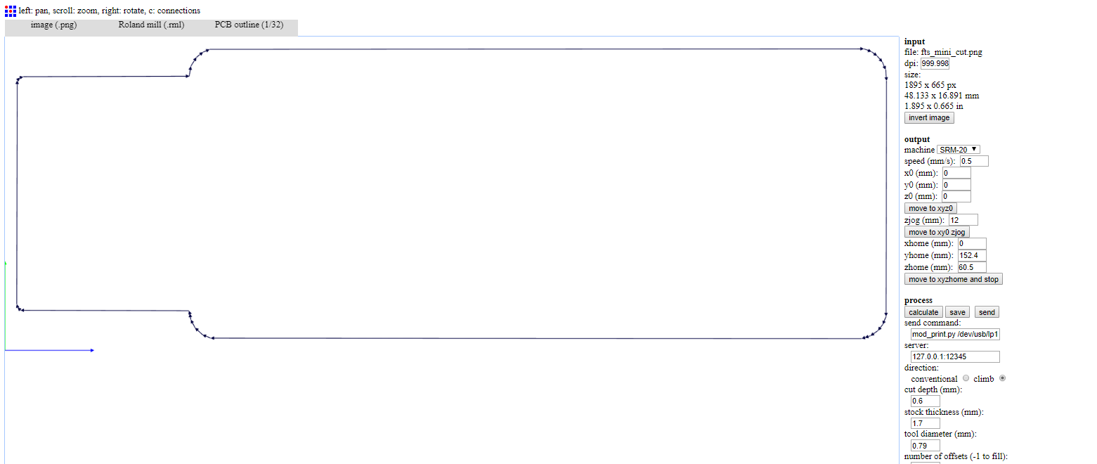
We followed the same steps to make our PCBs.
Download rml file (right click + Save link as)
Using VPanel
There is be a piece of wood taped down on the machine securely. We applied double sided tape & placed and pressed the board down on the sacrificial board securely.
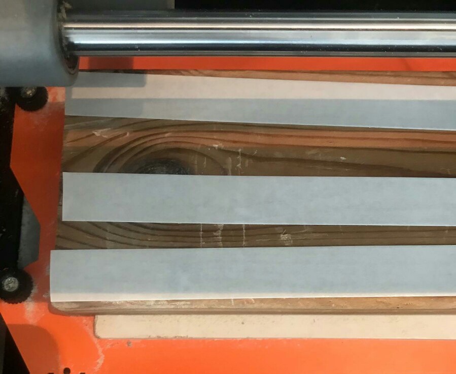
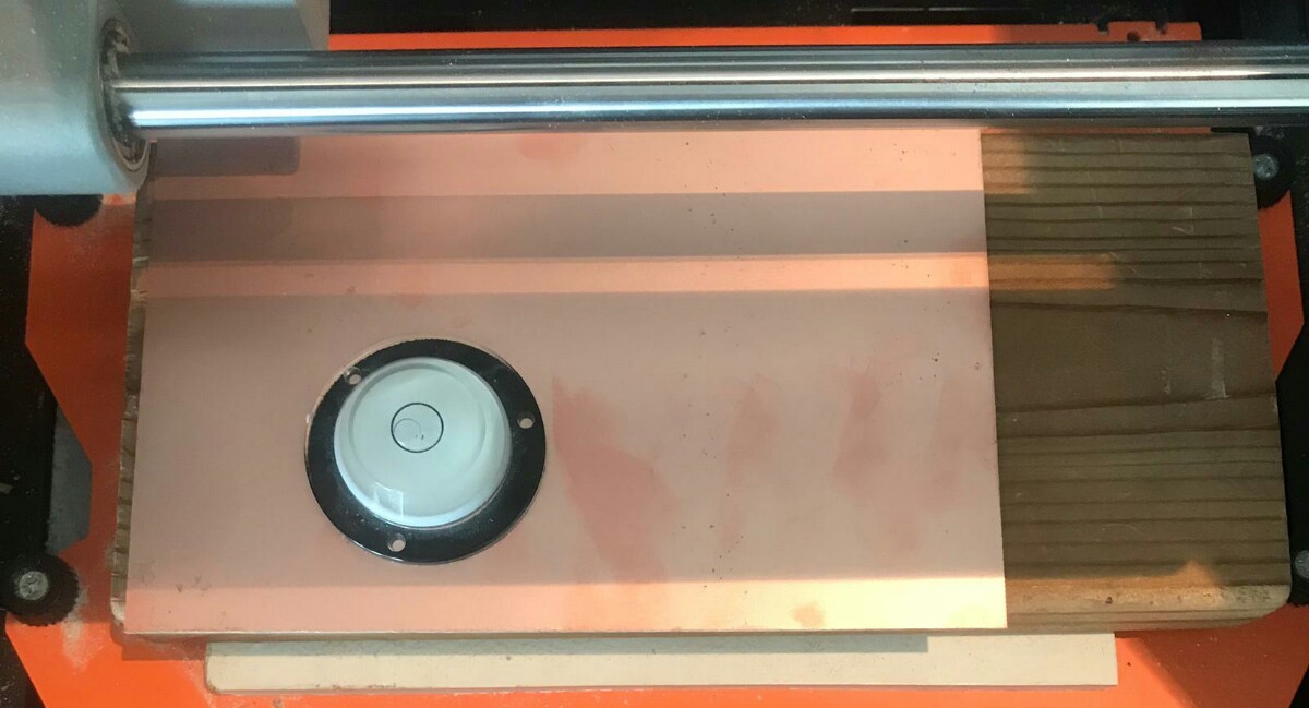
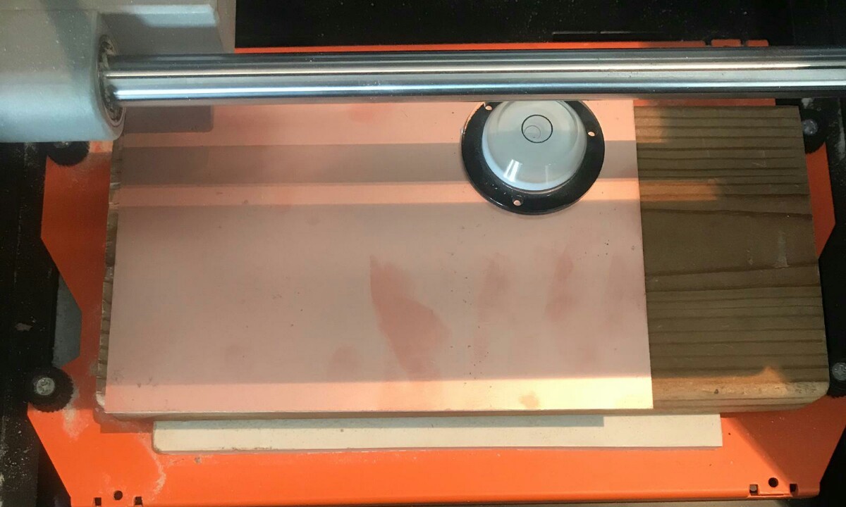
Then, we used a leveler in all corners to make sure that the PCB is leveled.
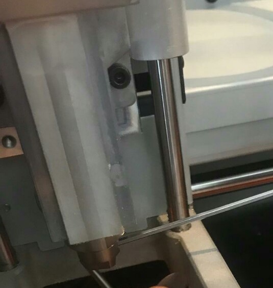
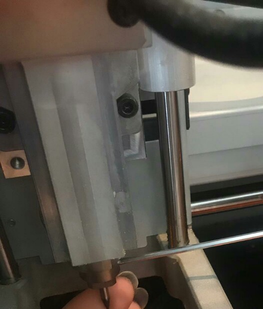
We turned on Roland Modela and opened VPanel for SRM-20. We inserted a new milling tip to the machine and we screwed it. Then, we warmed the spindle for 5 min at mid Rpm before using it.
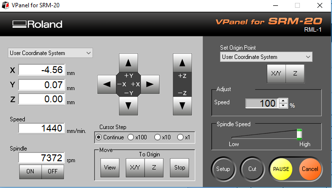
We adjusted the X/Y origin point by moving the tip using the arrows and saved the origin. We adjusted the Z origin by moving the tip down untill it almost touched the surface of the PCB then we released the screw of the tip to let it touch the surface and we pressed the PCB board slightly down then we tightned it again and saved the origin.
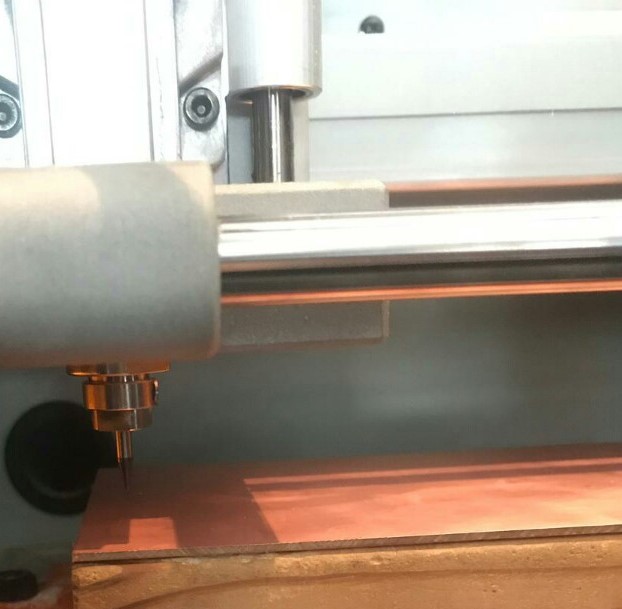
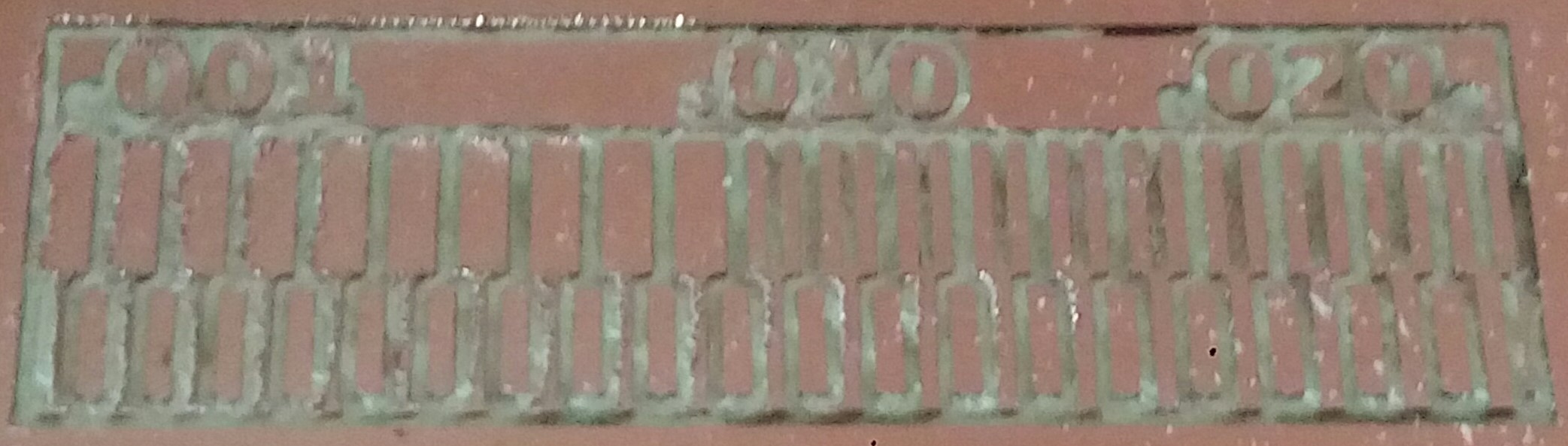
We clicked “Cut” on the control panel. A new window appeared we selected the traces cutting file, then clicked Output and the machine started.
We cleaned the board and replaced the bit to 1/32 to do the outcut. After zeroing the Z (only the Z) we clicked “CUT” in the control panel and we choose the outcut (outline) file and clicked Output.
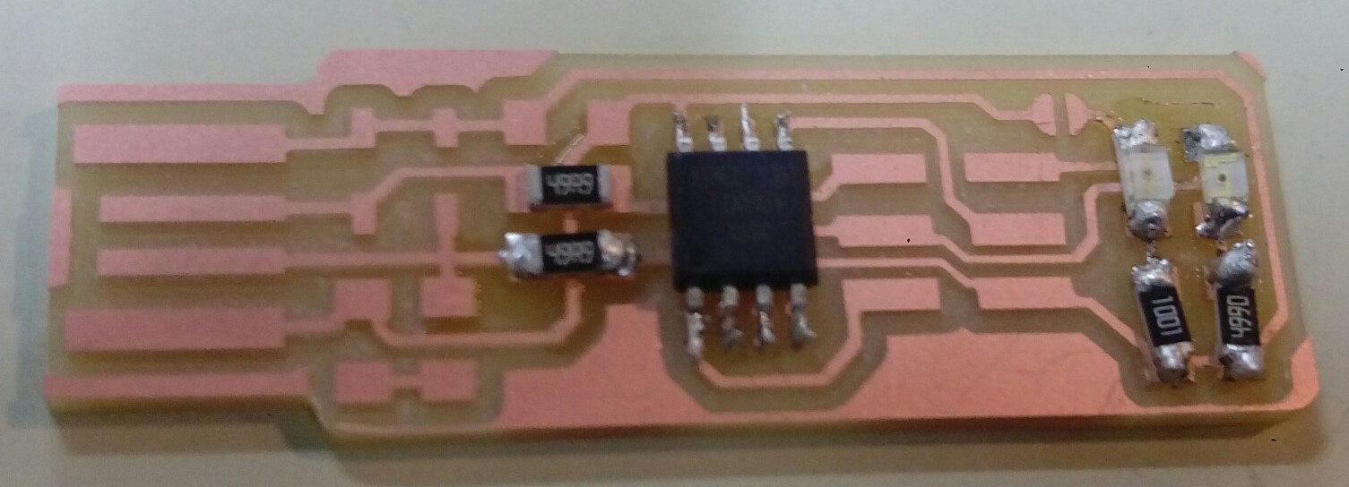
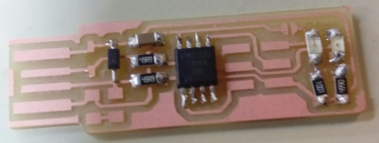
Soldering
For soldering I followed the diagram & the following Steps. At first I tried to solder a component on another circuit to get used to the process since it’s been a while since I last used it. I did resolder some of the components & I did continuty testing after almost every component to ensure everything is fine.
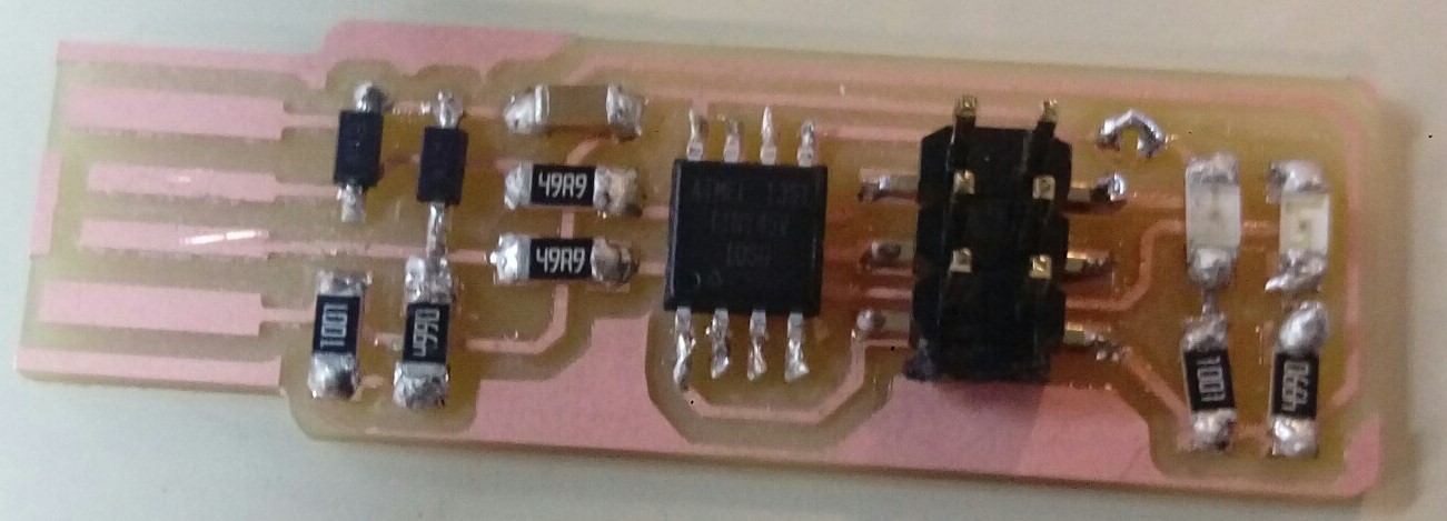
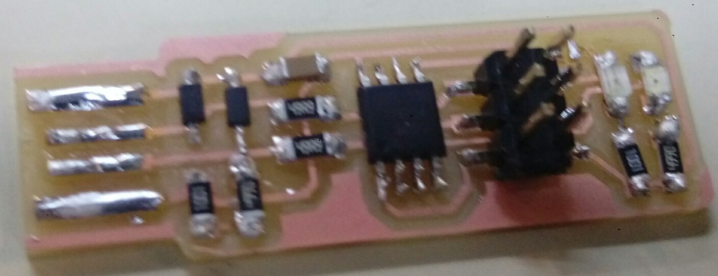
This is my hero shot.
Programing
For programming I used the lab Mac PC & followed these Steps. I used our instructor Duaa programmer to program mine & it worked from the first time.
1.I had to download and install CrossPack & firmware source code.
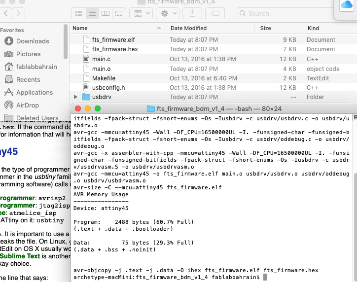
2.I opened the terminal program and cd into the source code directory & then run make. This will build the hex file fts_firmware.hex that will get programmed onto the ATtiny44.
3.Using the two connections wired my PCB to the lab pc and in the other side to the programmer.
4.Run make flash.
5.Run make fuses.
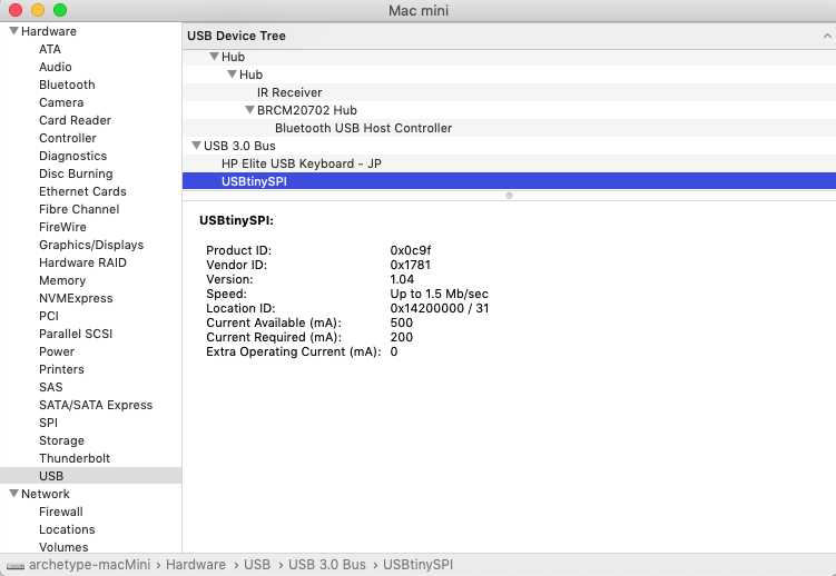
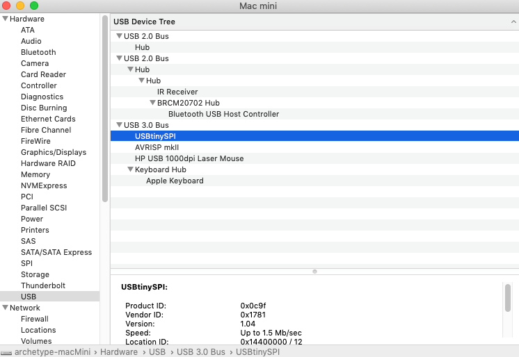
6.Selected USB from the list on the left, and the USBTiny was listed as a device on the right.
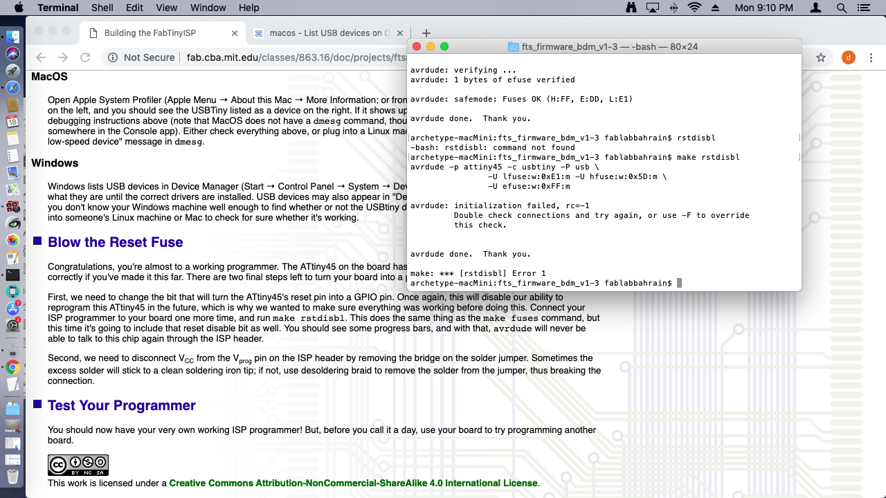
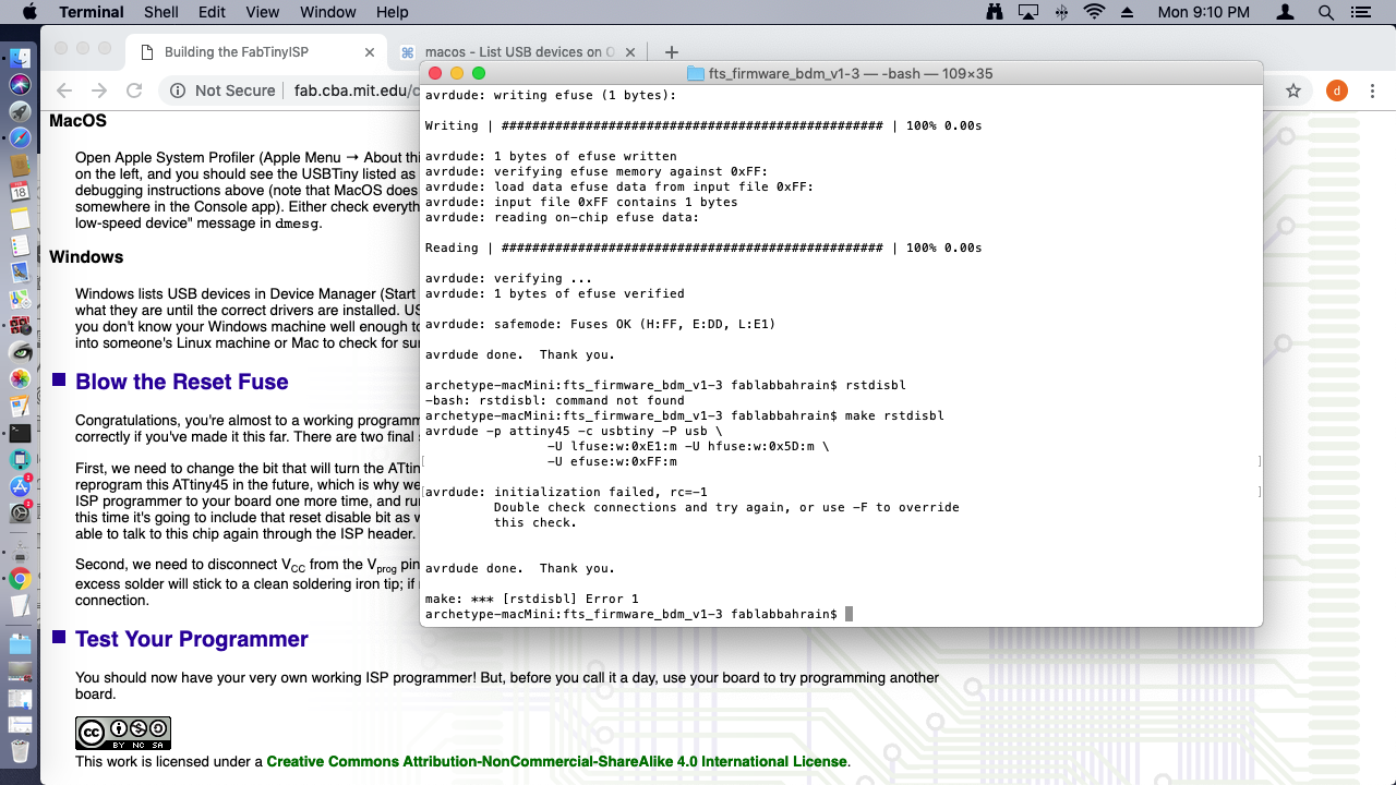
7.Run make rstdisbl.
8.Removed the jumper solder.
Reprogramming
It turned out that there was an error in the previous programming. So, I had to resolder & repeate the previous steps using AVRISP MKll.
1.I had to download and install CrossPack & firmware source code.
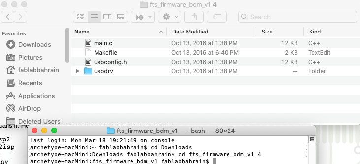
2.I opened the terminal program and cd into the source code directory & then run make. This will build the hex file fts_firmware.hex that will get programmed onto the ATtiny44.
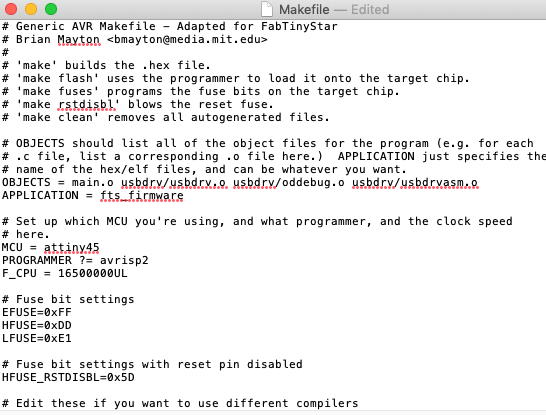
3.I have updated the Makefile for the type of programmer I am using.
4.Using the two connections wired my PCB to the lab pc and in the other side to the programmer.
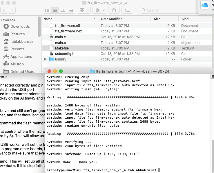
5.Run make flash.
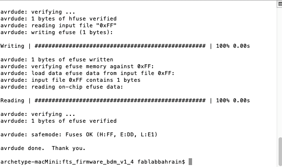
6.Run make fuses.
7.Selected USB from the list on the left, and the USBTiny was listed as a device on the right.
8.Run make rstdisbl.
9.Removed the jumper solder.