Communicating one project to another for fulfilling this lesson's goals is possible by linking my phototransistor board with my RGB light board. I try to use what is needed in order to avoid producing garbage. So I wanted to integrate my final project's requirements into this lesson.
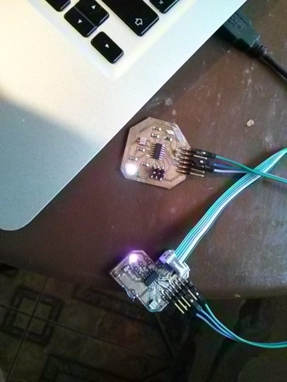
I was able to communicate one board to another by making the LED blink with a certain sequence and detecting this sequence with a phototransistor on another board. The sequence is then reproduced by blinking a LED at the same rate on the receiving board as the LED on the transmitting board.
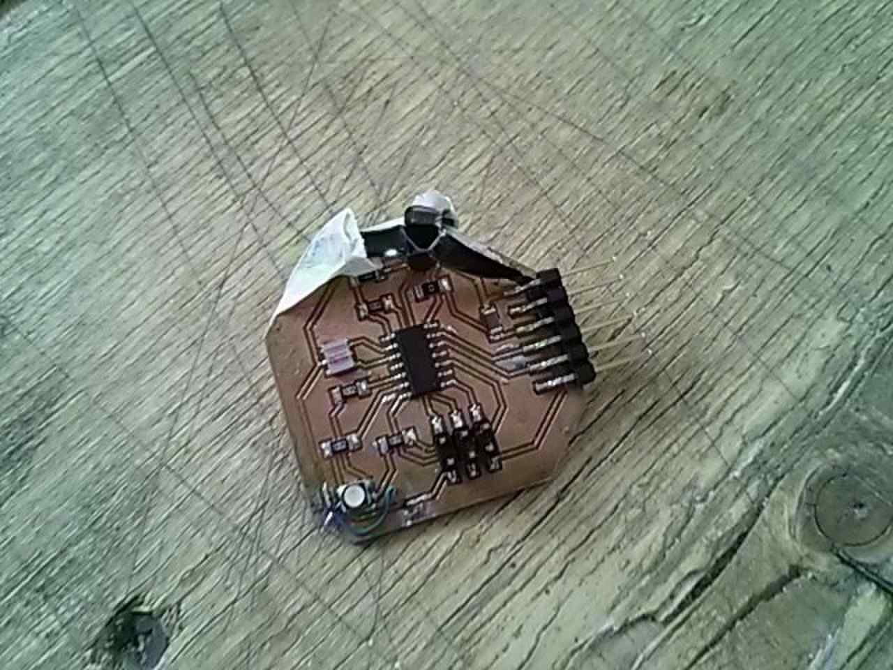
My receiver is the original output device board made on the output device lesson.
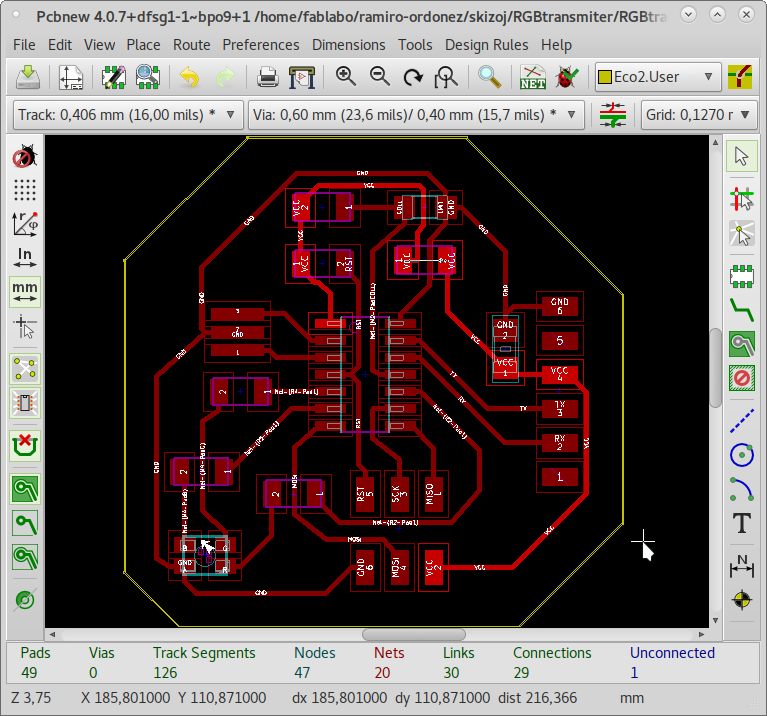
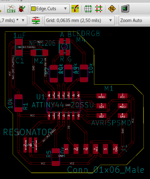
On the input device lesson I made an input device board which had the same components as the output device board but with an added RGB LED and a phototransistor. It serves as the transmitter.
I plugged the two to the same power source, my USB Tiny In-System Programmer. These did not communicate via wires. They communicated with each other via light pulses.
This arrangement was capable of communicating at less than 1m. But I want to transmit at a longer distance. So I used a cheap LASER as an addition to my transmitter.
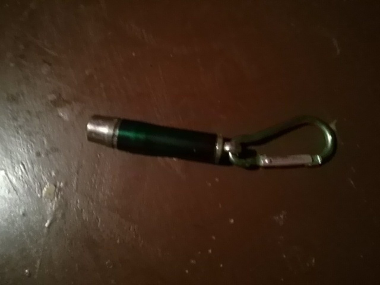
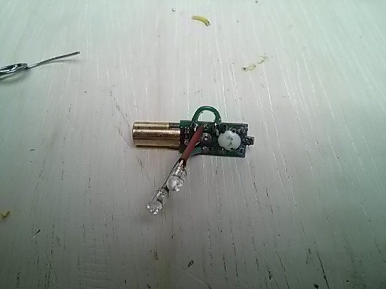
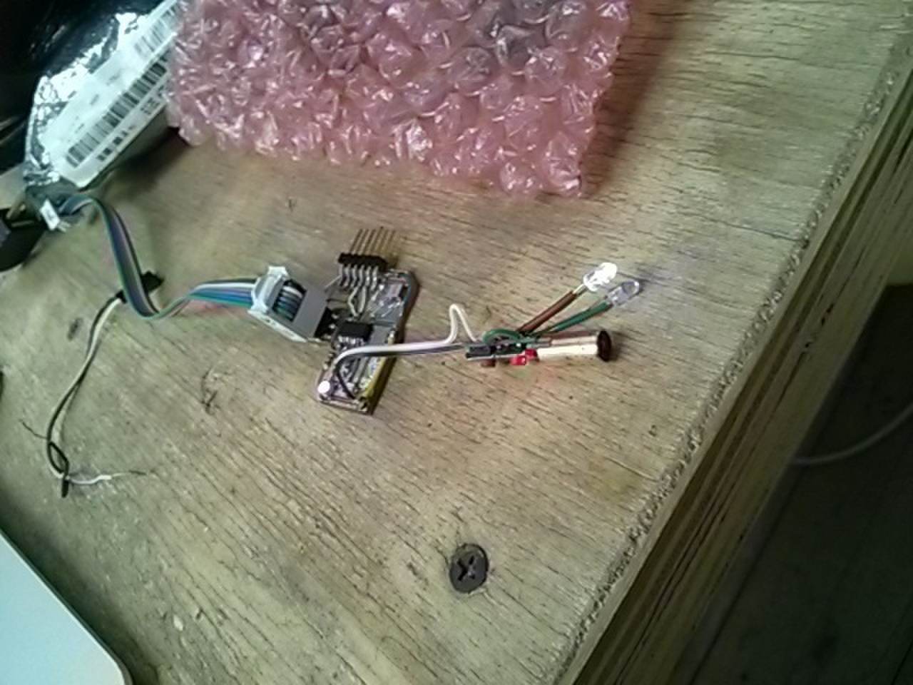
I have disassembled it.
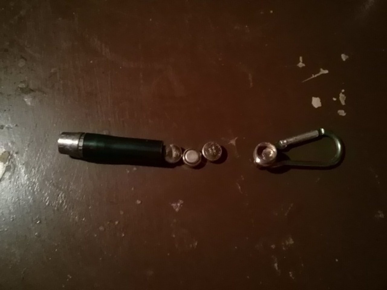
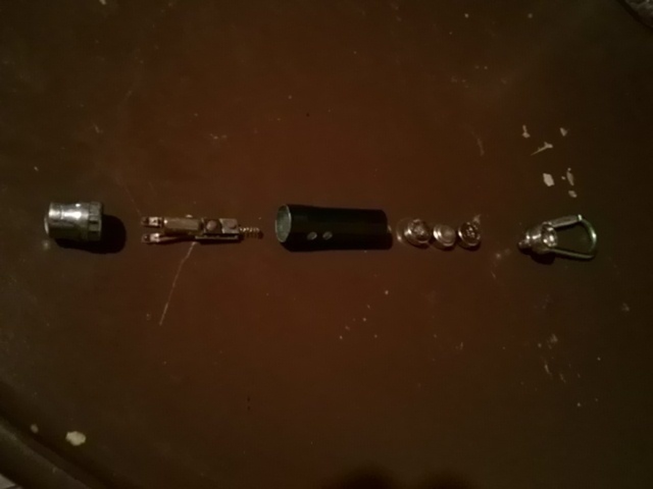
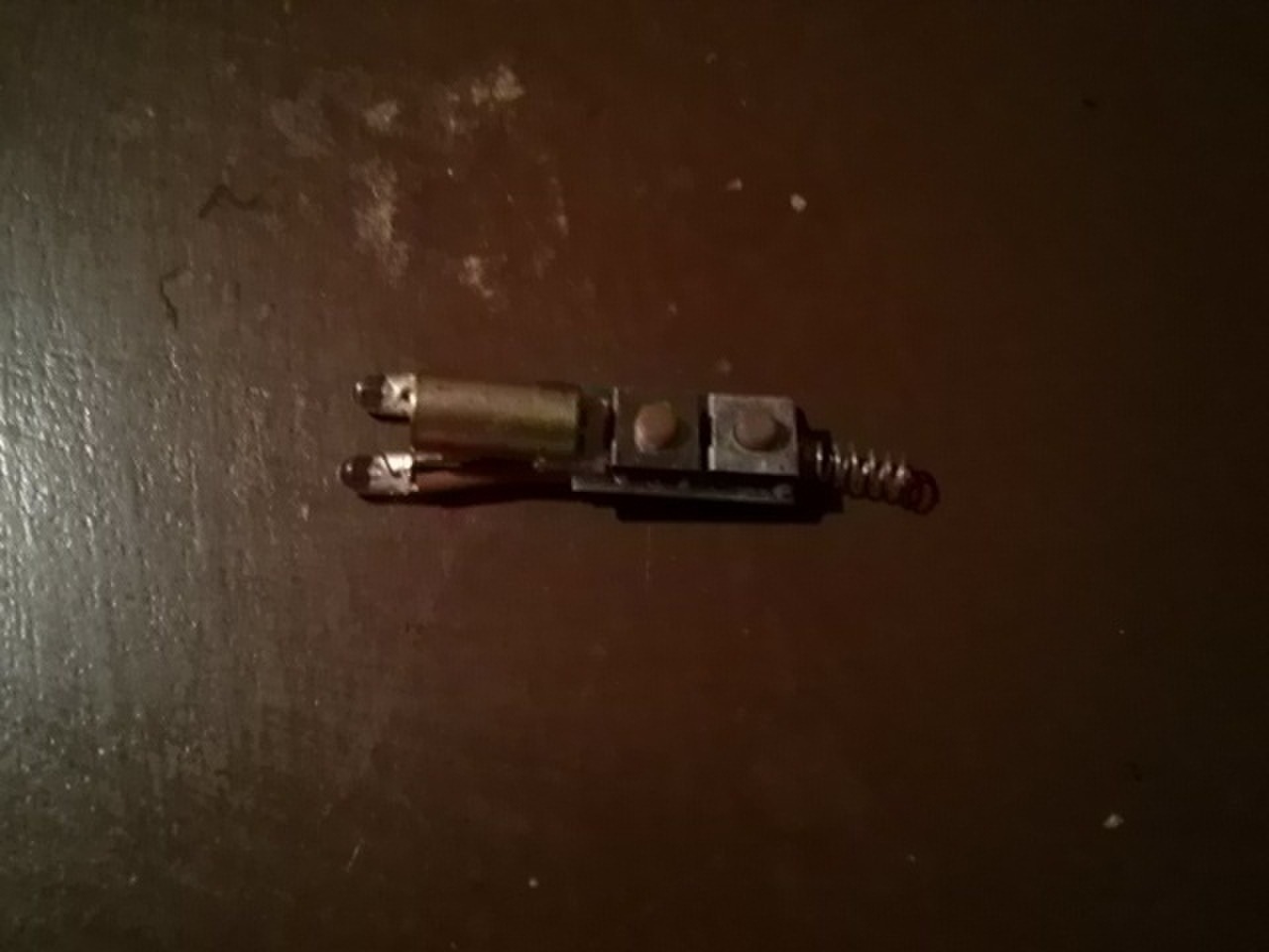
I just need the LASER the mechanism.
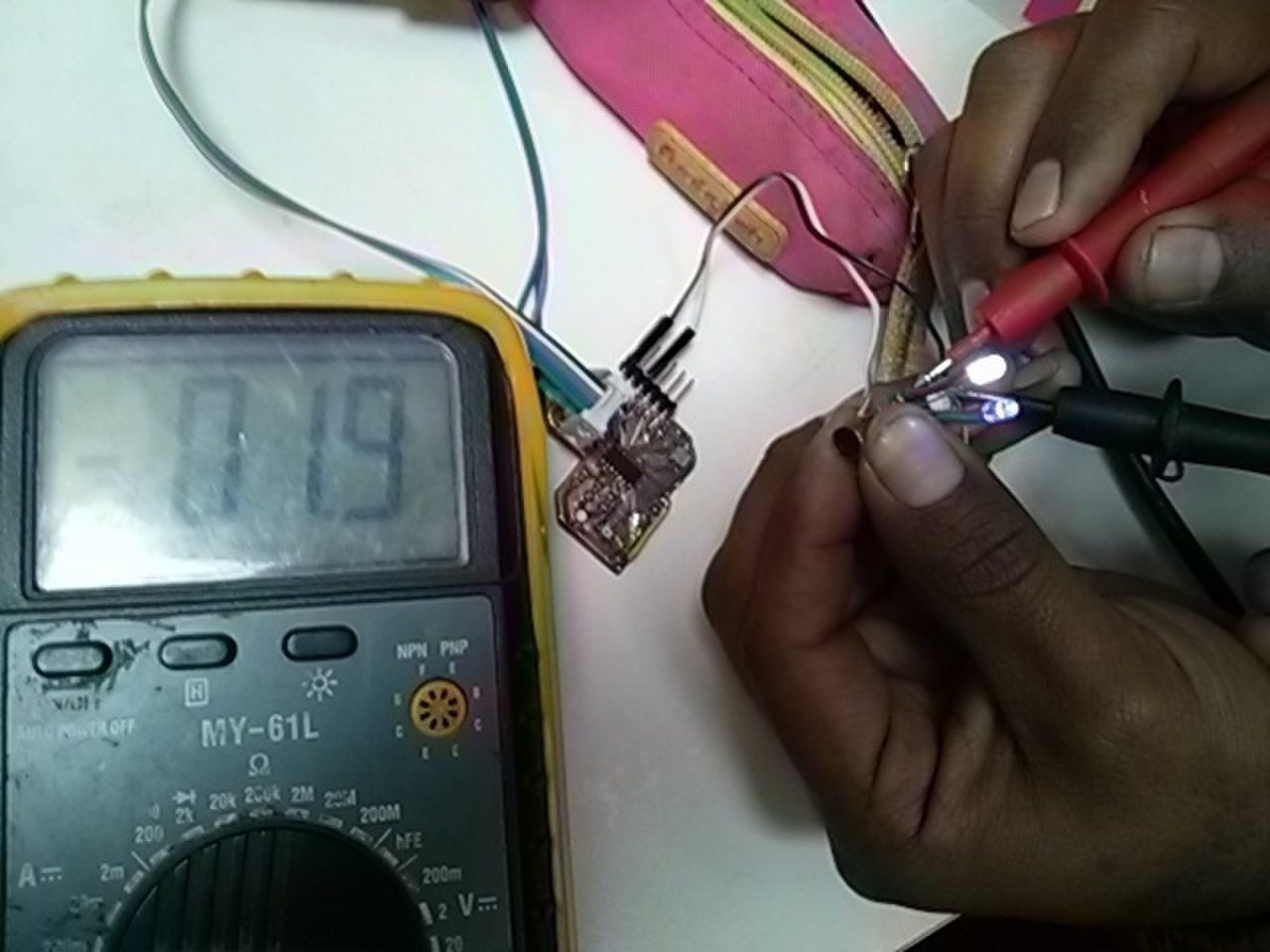
I measured the red, green and blue LEDs' resitances.
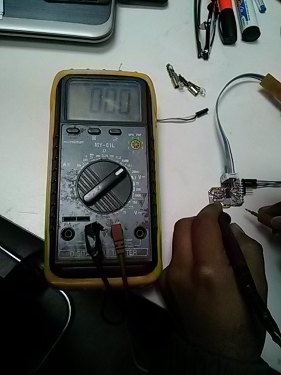
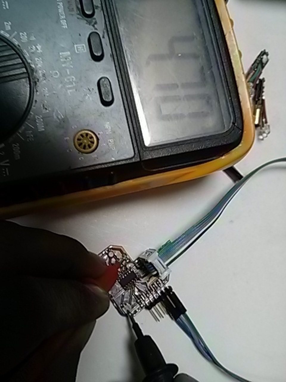
Then measured the LASER pointer's resistance.
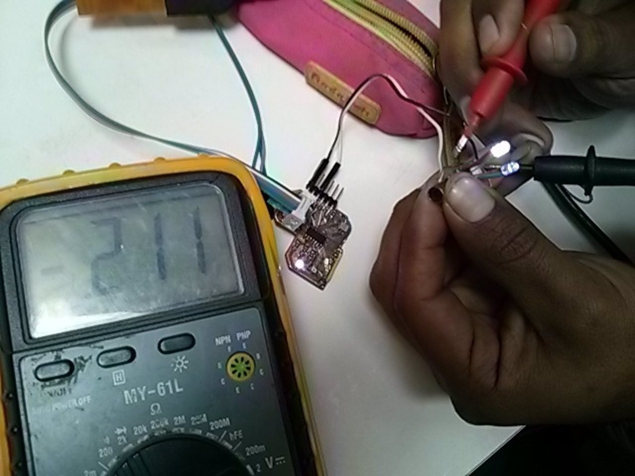
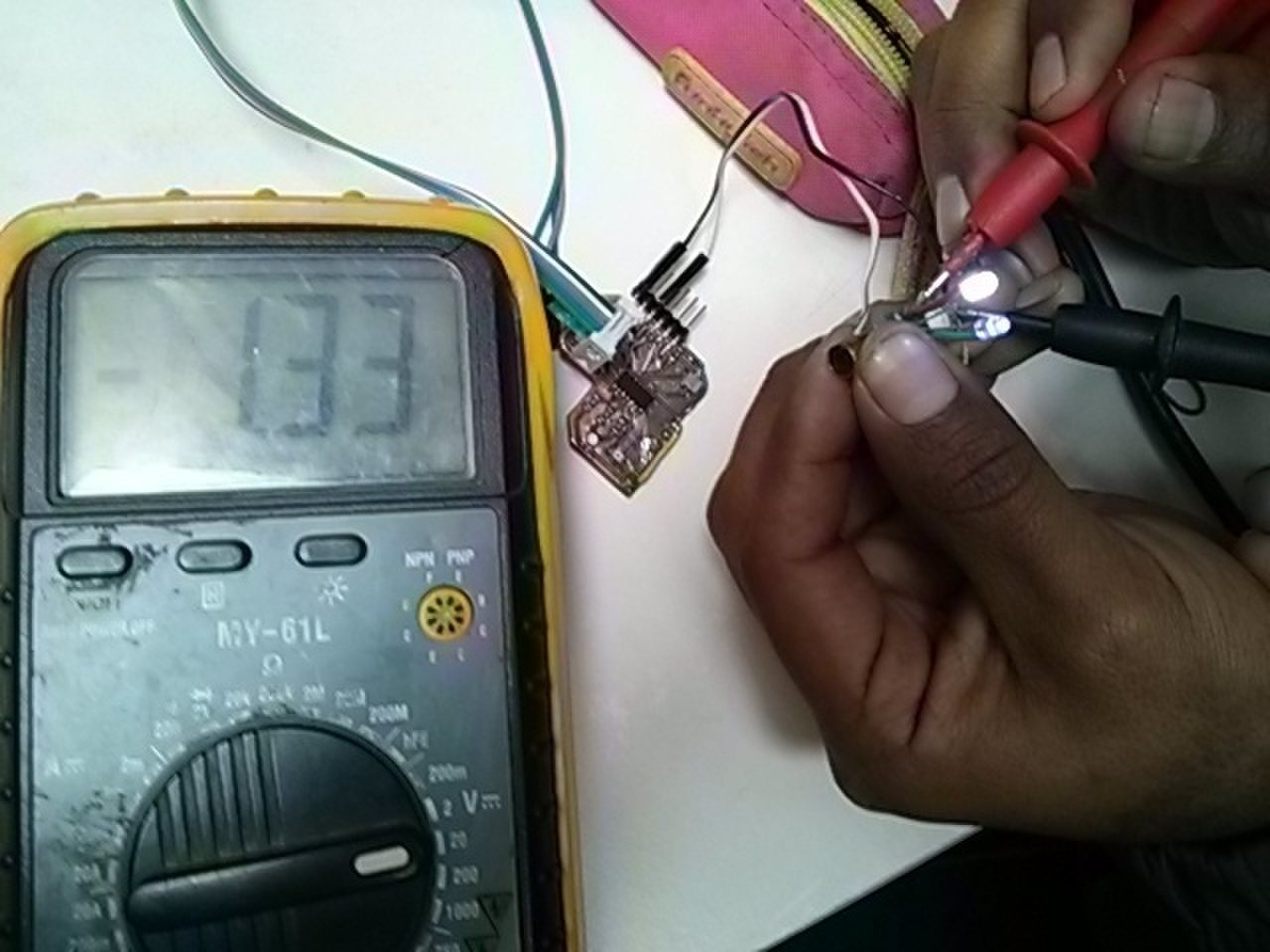
Since they were similar, I tested the LASER pointer with my board's voltage. Habemus luminum!
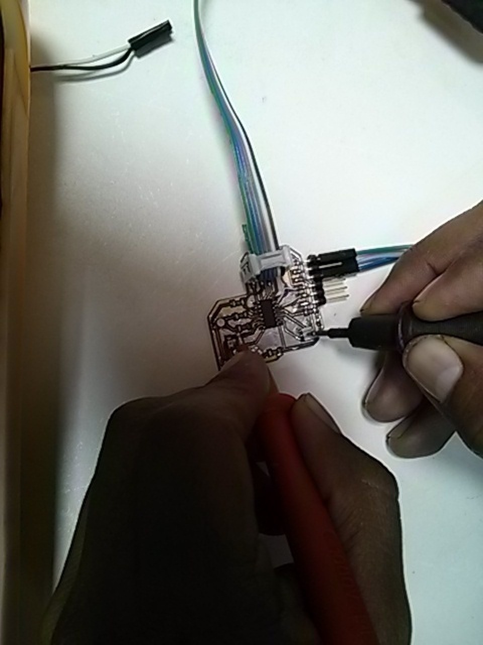
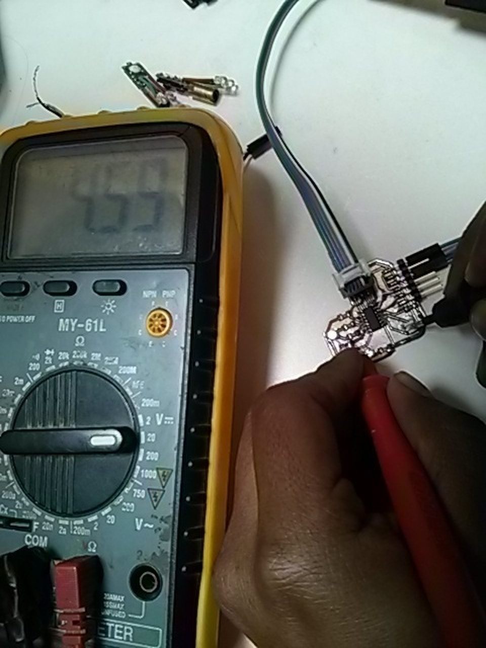
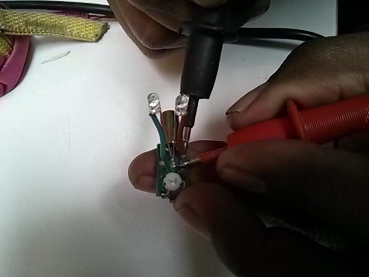
Then I measured the voltage drop at the two normal LEDs and at the LASER LED.
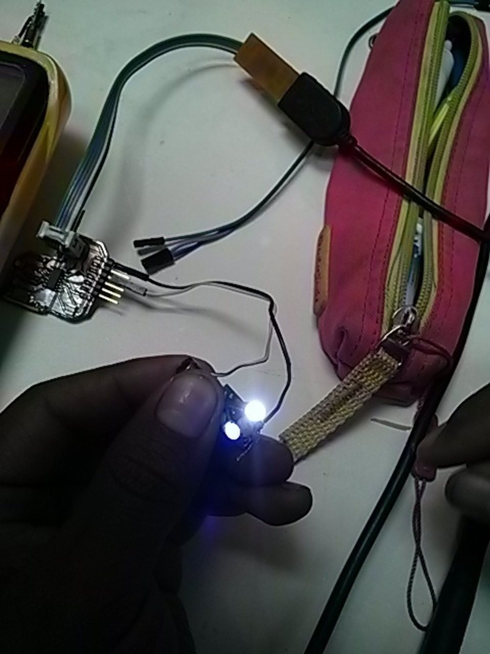
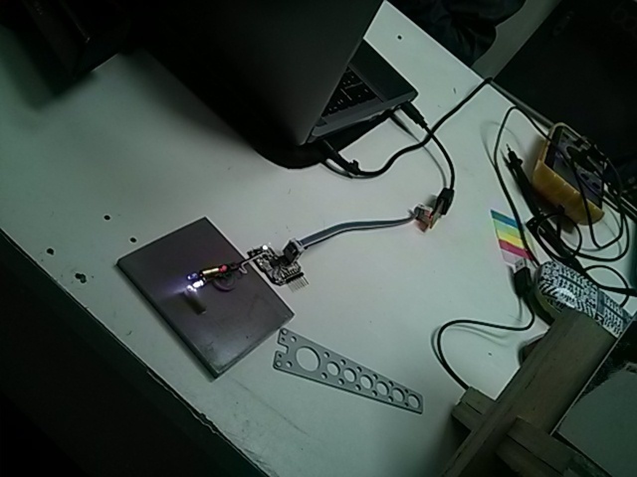
So I soldered wires to VCC and to the MCU pin that lit the most similar LED.
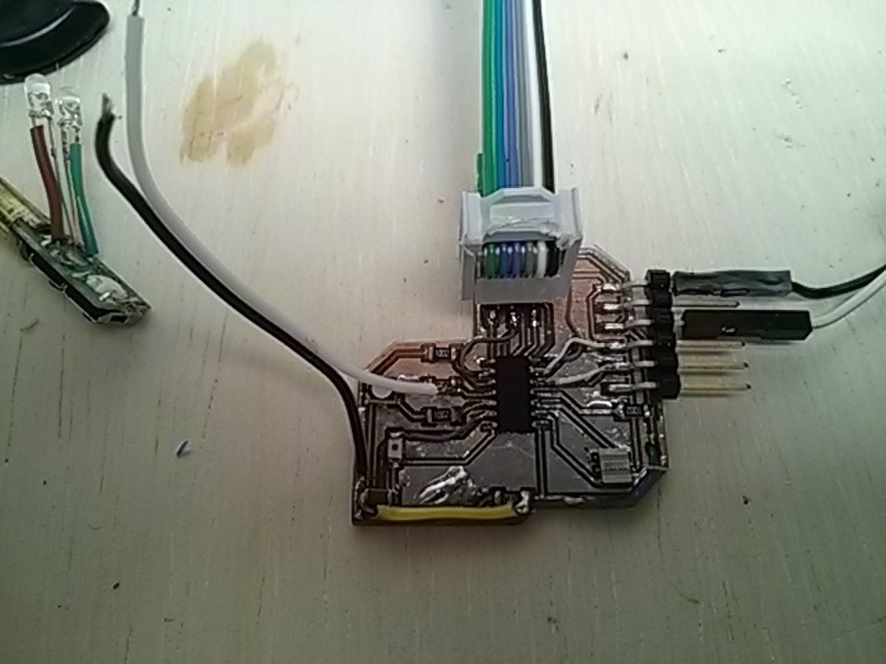
And I soldered those leads to the LASER LED.
I covered the surounding area of the phototransistor on the receiver board with a piece of plastic straw so that only direct light would trigger it and not just environment light.
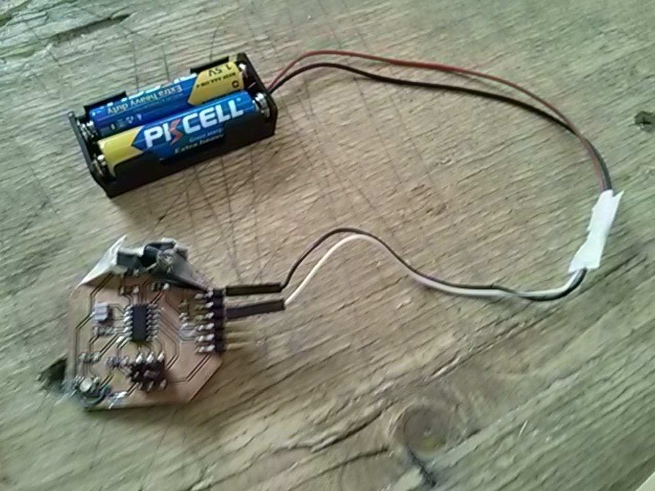
And connected a power source to the receiver board.
I set the receiver board at one end of the hall
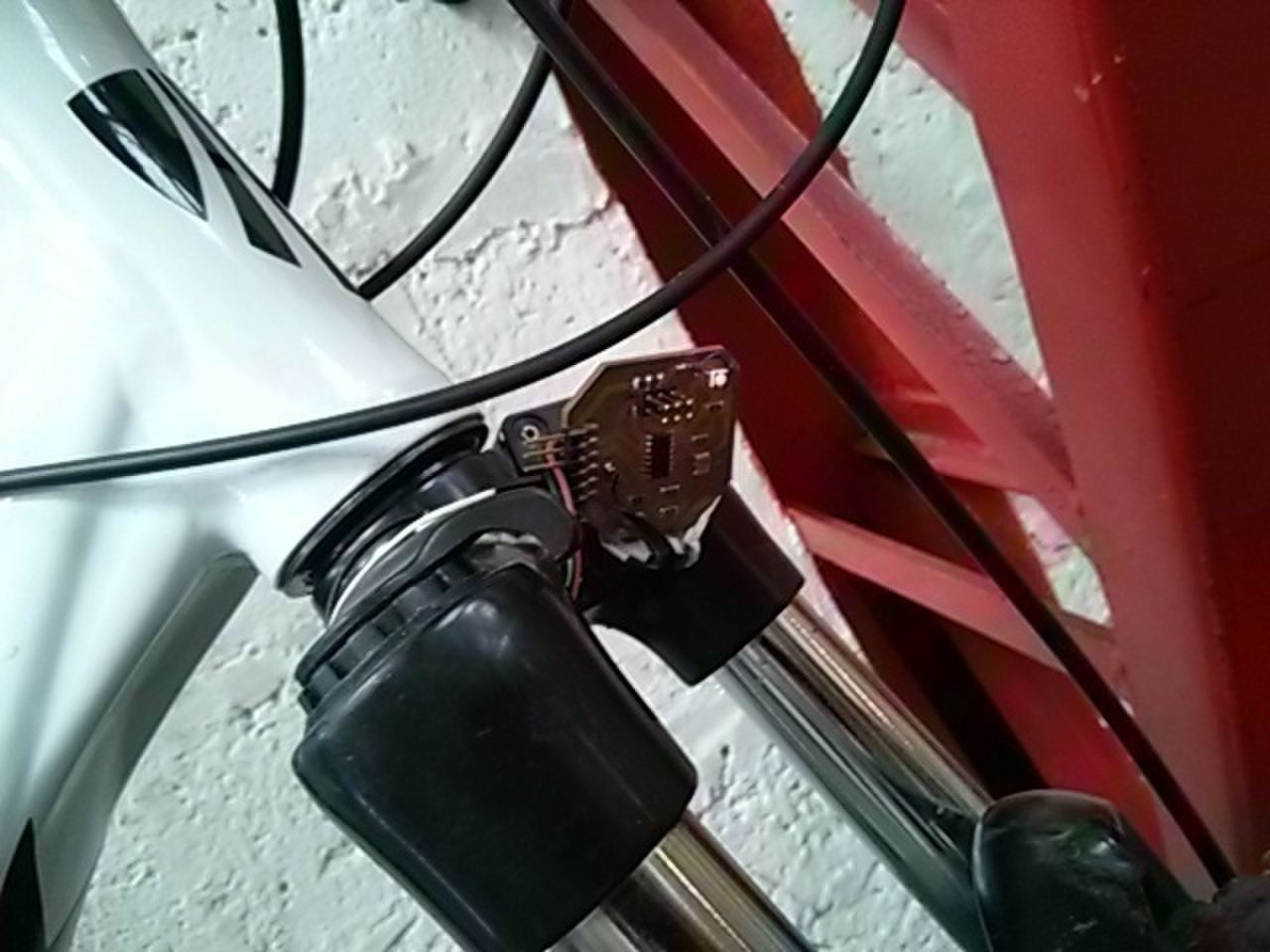
with the phototransistor in the piece of straw pointing at the other end of the hall.
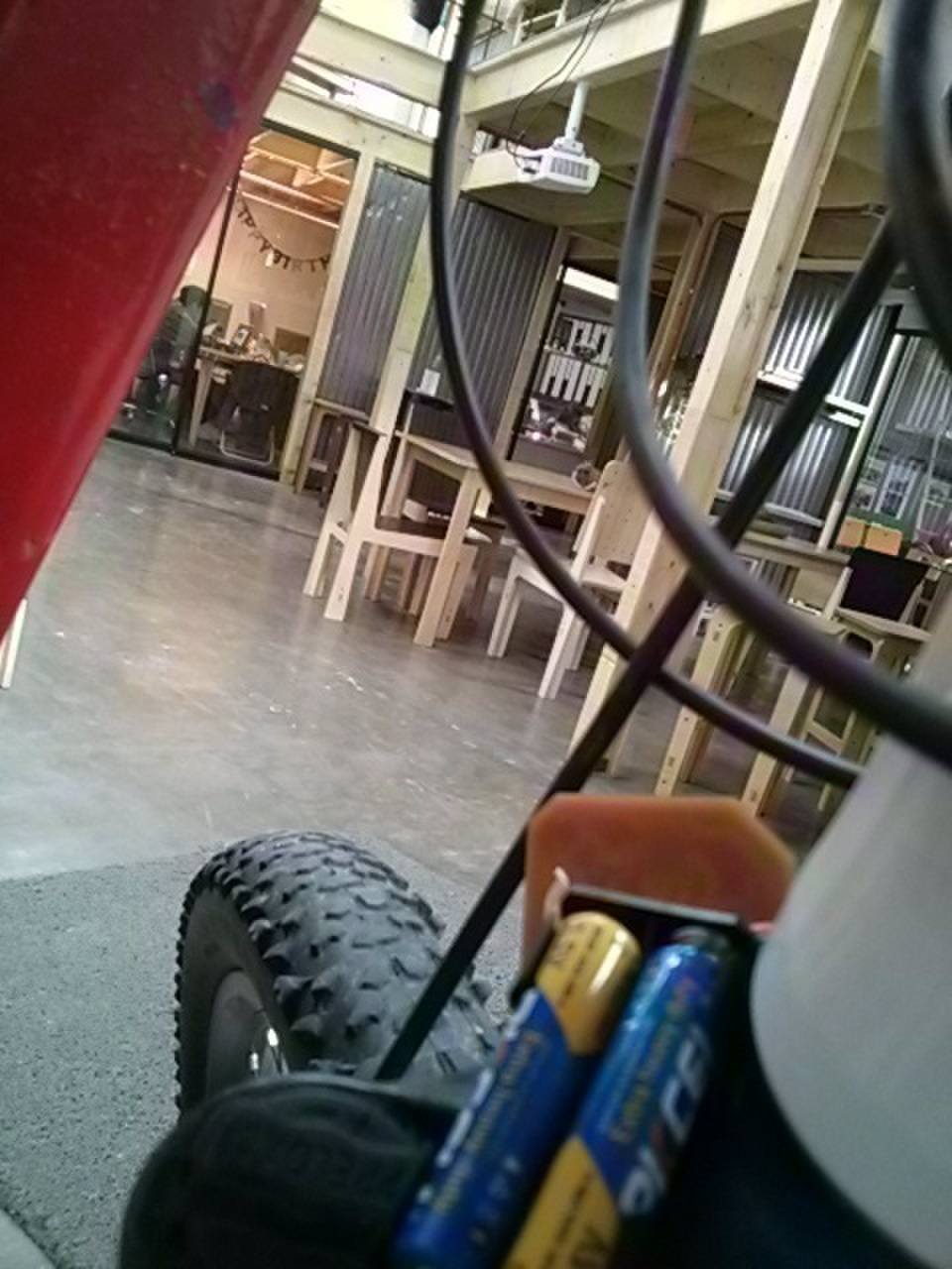
And I pointed the transmitter on that other end of the hall towards the receiver. It was connected to a computer as a power source.
Pointing took about 40 minutes. But the transmission was finally achieved. Here is the video of a transmission at 32 meters.
The programs used a simple sequence of pulses. The transmitter turned the LASER LED on and off. The receiver phototransistor powered the receiver LED at the rate that it received light from the transmitter. It is explained in the embedded programming lesson.
Light can travel very long distances. The problem is interference of environment light. This can be solved with synchronous detection. This synchonous detection demonstration video shows what is possible.
Pointing the devices is a very tedious process. Perhaps screws to calibrate vertical and horizontal angles would be handy. Also a telescope as a mechanical tool or a handheld device as a digital tool could help.
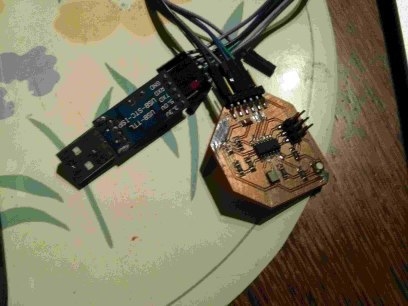
Since there is no way to connect the USBtinyISP as a communications device similarly to the Arduino ONE, I can connect one of my boards to the other through a Prolific PL2303 Serial Port. The output of lsusb is:
Bus 003 Device 017: ID 067b:2303 Prolific Technology, Inc. PL2303 Serial Port