In this excercise I design and fabricate a PCB with a MicroController Unit (MCU) with a Red, Green and Blue LED. I made a program so that it blinks in a certain sequence.
I use the same design which I made for input devices since I include a RGB LED on that PCB. I just use the board that has the correct polarization for a common anode instead of a common GND on the RGB LED.
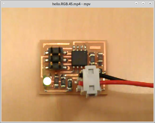
This exercise gets me closer to constructing a working telecommunications device. I have chosen a RGB LED from Fab Inventory. This device has 3 cathodes (1 for each LED) and one anode. I added this device and removed the switch from the input device design in order to have enough pins for this assignment. I used the hello.RGB.45 from Neil's examples as a guide to add the 3 color LED to my own design
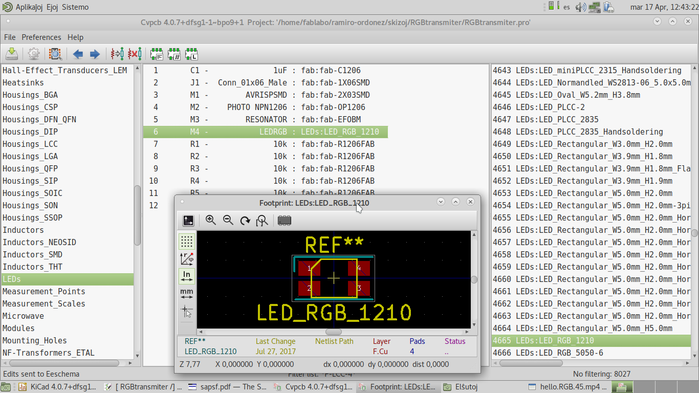
When adding the components, I just needed to add the RGB LED association with KiCAD's CvPCB.
Perhaps I can add one phototransistor for each of the 3 colors with charlieplexing on my final project to detect them all at once (using only 3 pins to drive 3 LEDs and 3 phototransistors) and employ synchronous detection for making very precise measurements with just another phototransistor that detects ambient light.
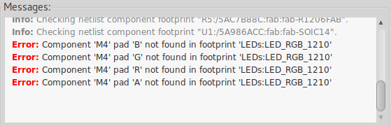
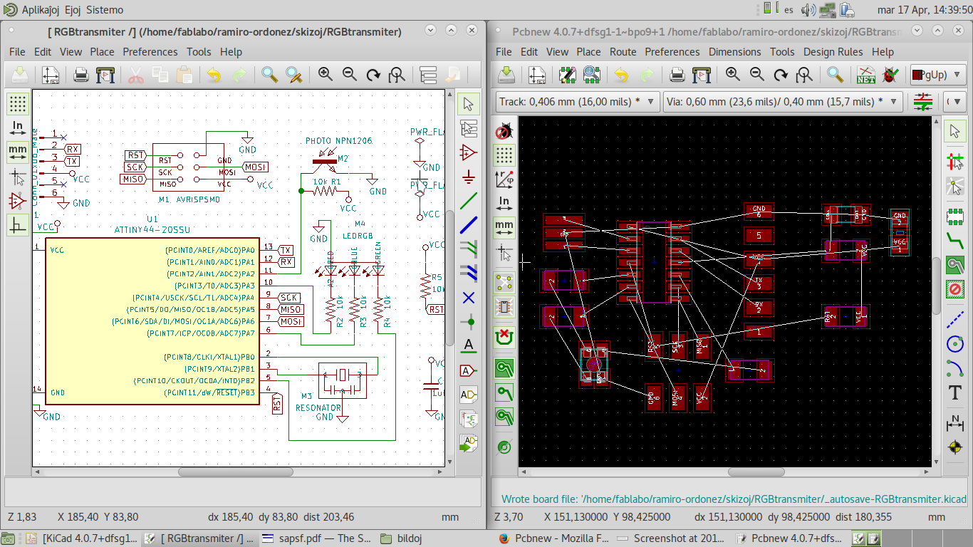
I ran all the Electrical Rules' Checker (ERC) and got 2 errors.
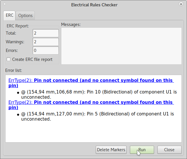
And the arrows showed the places where they were.
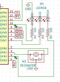
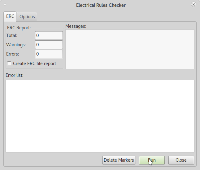
After connecting the threads correctly, the ERC could find no errors.
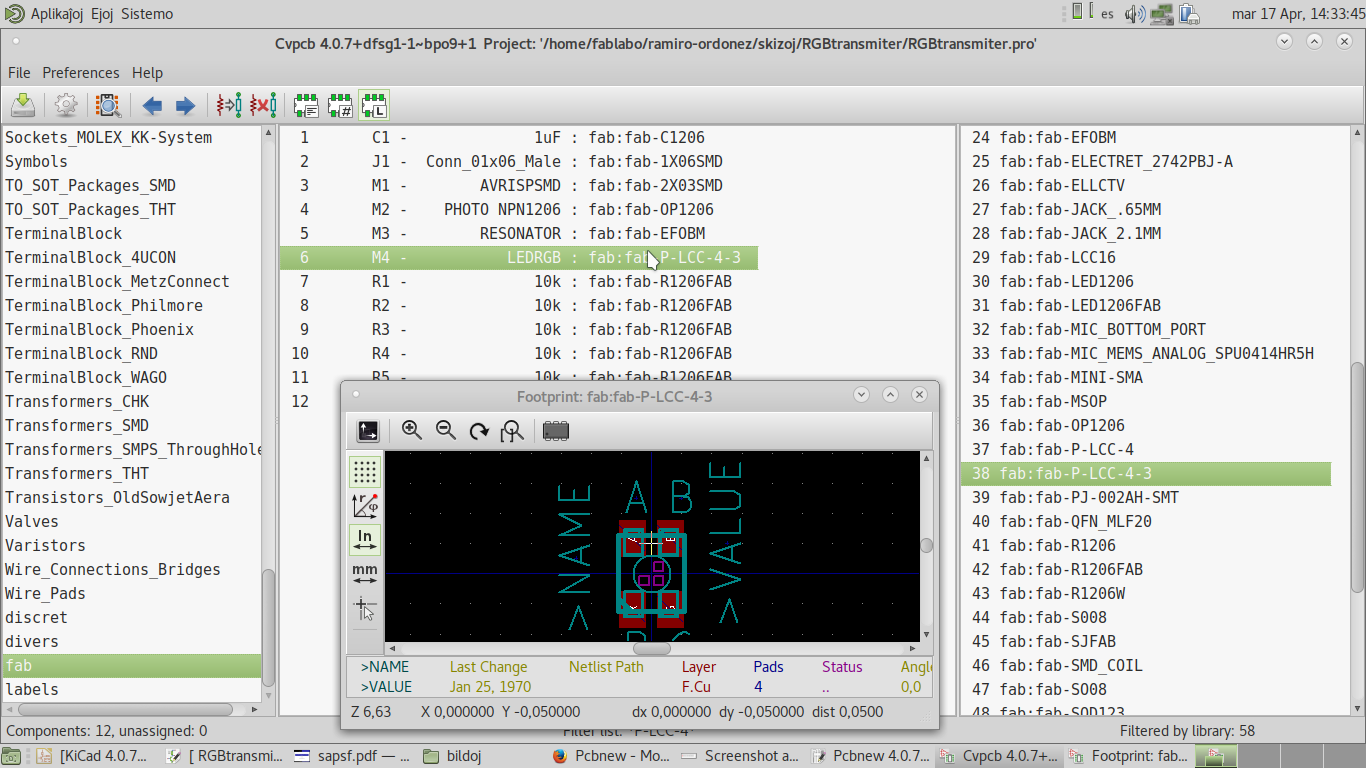
When assigning the components, the RGB LED did not have a footprint yet.
So I assigned LEDRGB from the Emanuele Goldoni's previously added FabAcademy KiCAD component libraries.
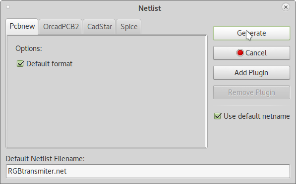
Generating the netlist allows to make a file that contains the component connections.
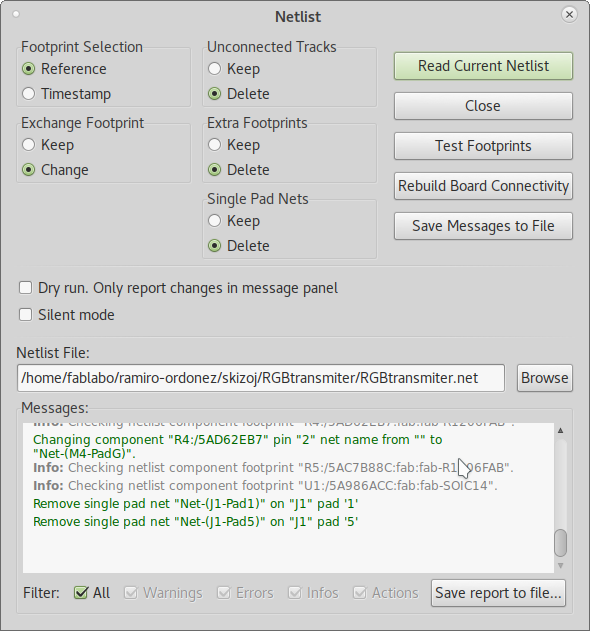
Reading the netlist on PCBNew allows to import the components and connections to make the traces on the PCB.
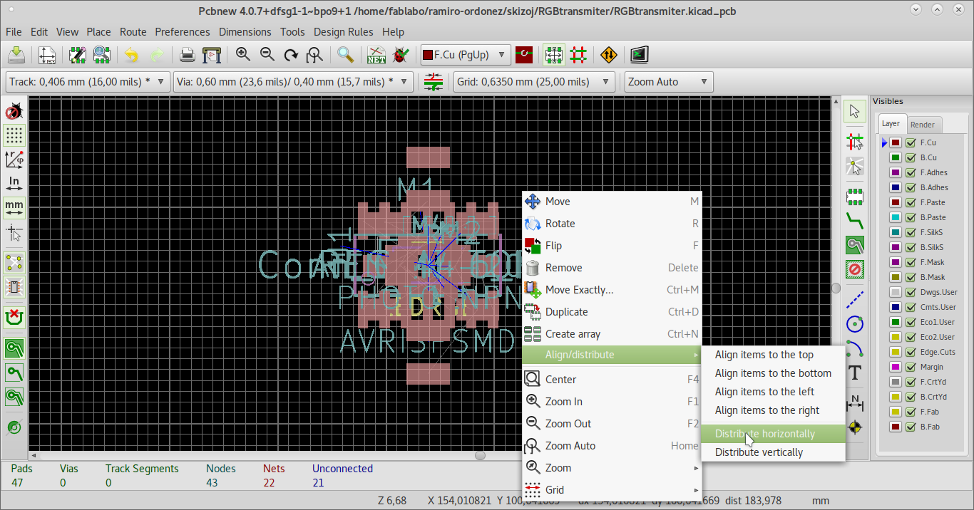
Distributing the components in order to place them on the available space is done with this button.

This is for distributing them horizontally.
I tryed to place the components equally separated.
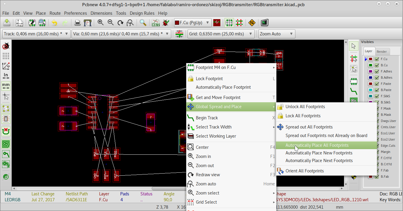
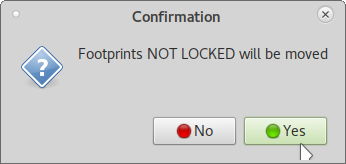
But this tool needs a board edge which I did not trace yet in order to distribute the components.
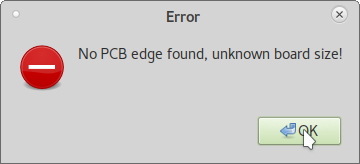
I placed the components manually.
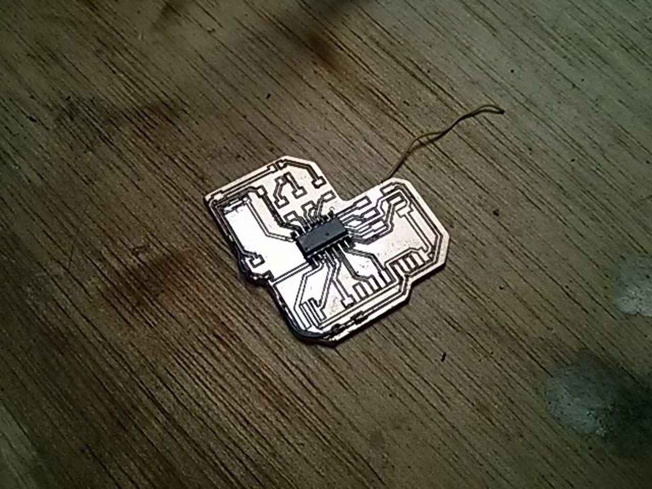
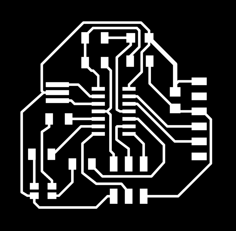
So this is the final trace and cut system.
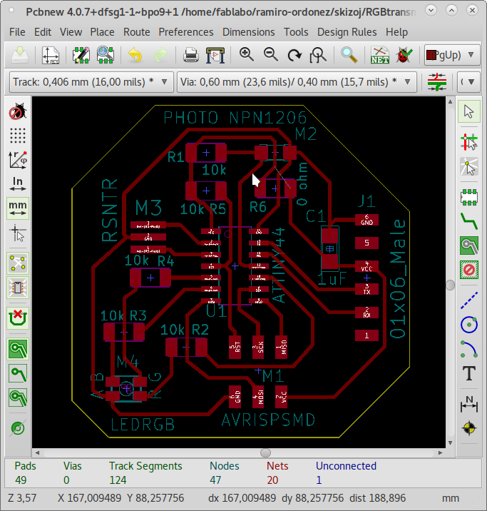
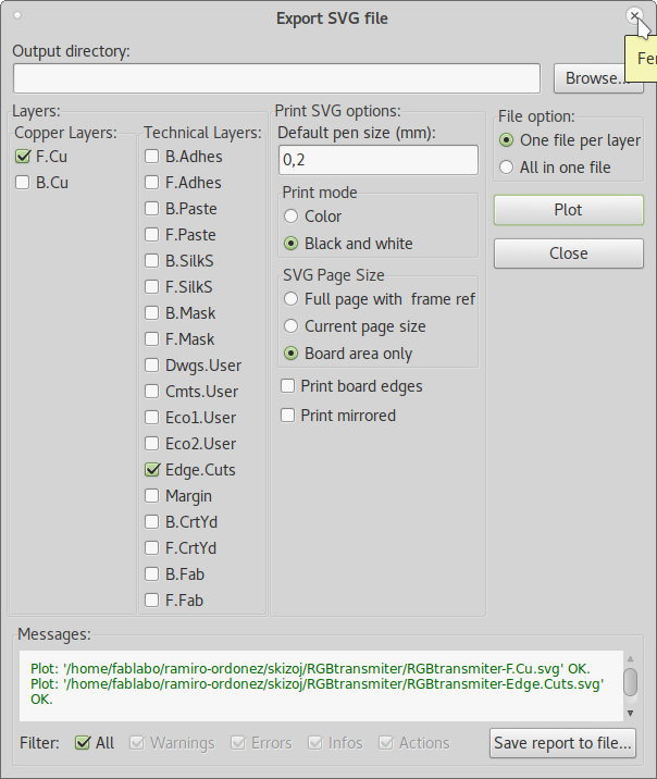
Now I could export the traces and cuts to 2 different SVG files.
Opened the SVG in Inkscape and exported the page to PNG.
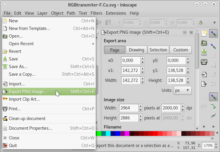
At 2000 DPI. (Notice the size became excesive.)
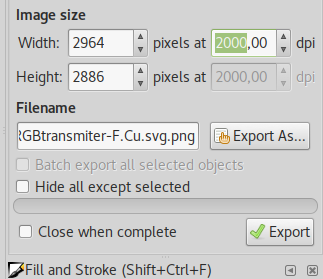
With these images:

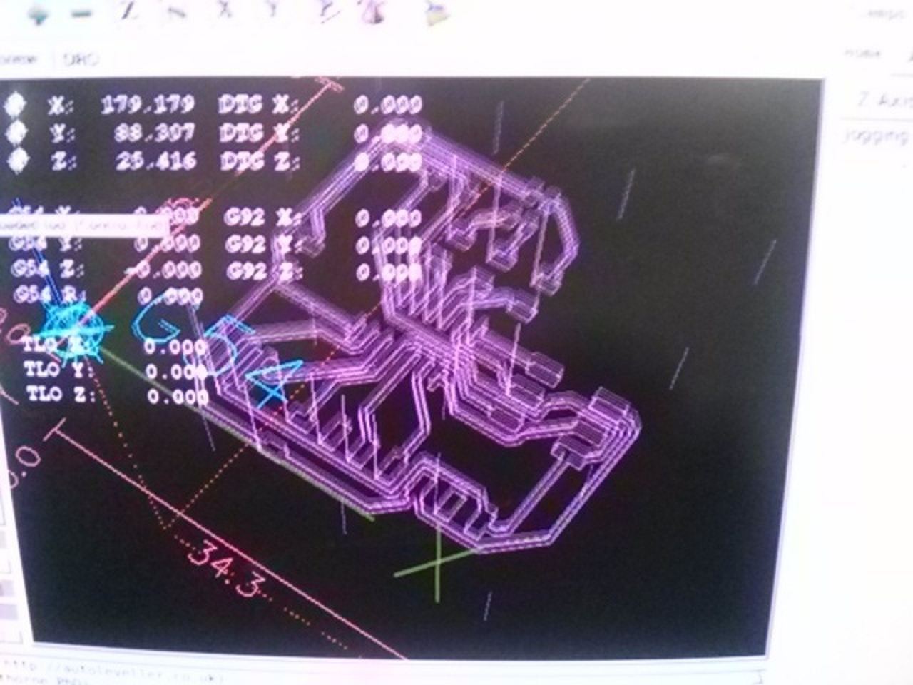
In Fabmodules I produced this cuts' and this traces' G-code files.
I just used Arduino IDE's digitalWrite() to turn the LED on for a certain lapse. Then turn it off for another lapse with delay(). The LED sequence of pulsing is described in the embeded programming lesson.
Then I could pulse in 7 different colors by alternating which LEDs glowed and which did not. I made it do that with a for loop which diminished the interval in ever increasing time lapses as also described in the embeded programming lesson.
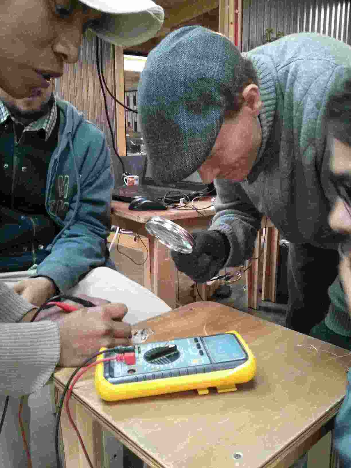
As a group, we tested the voltages at each component.
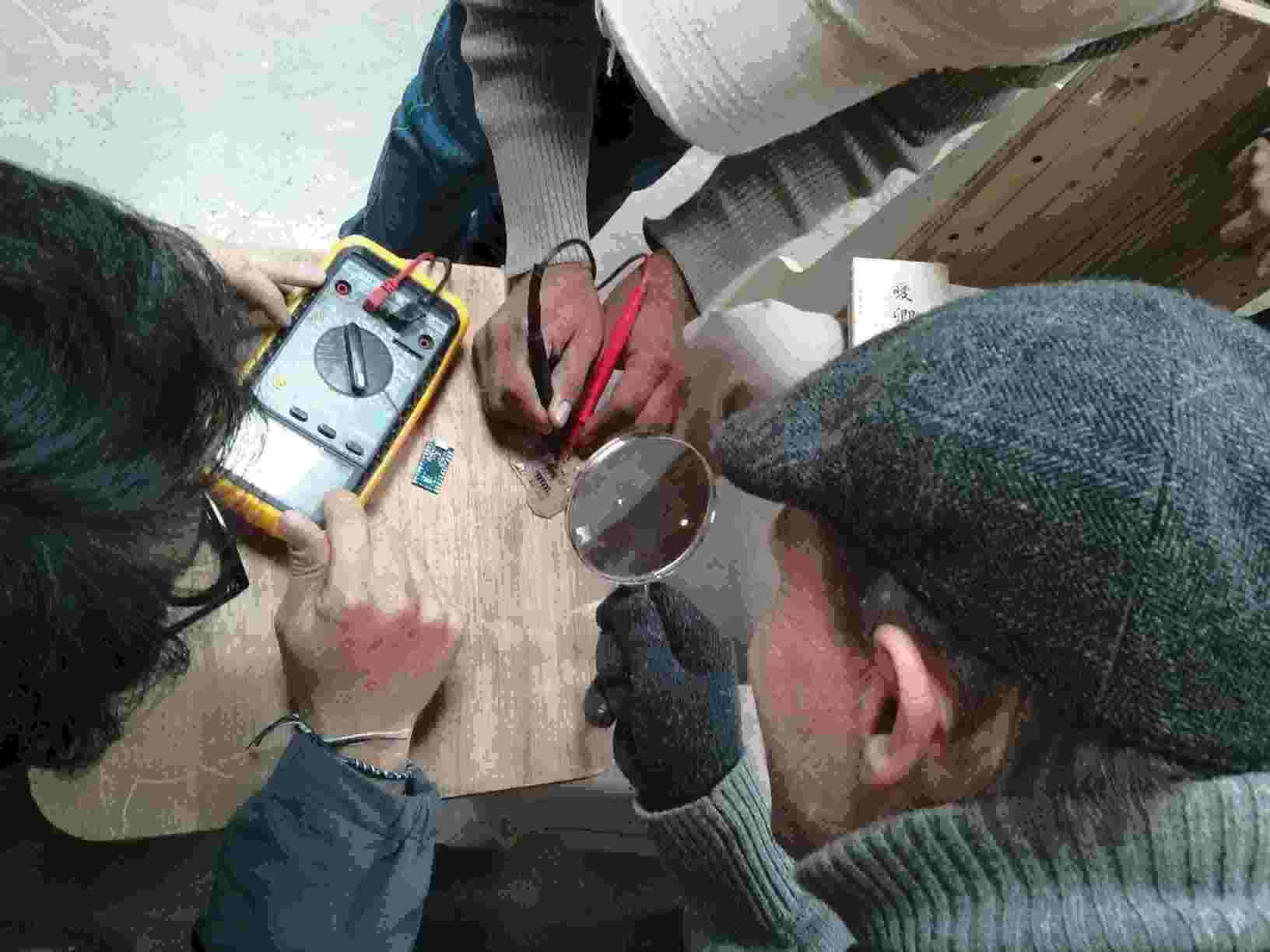
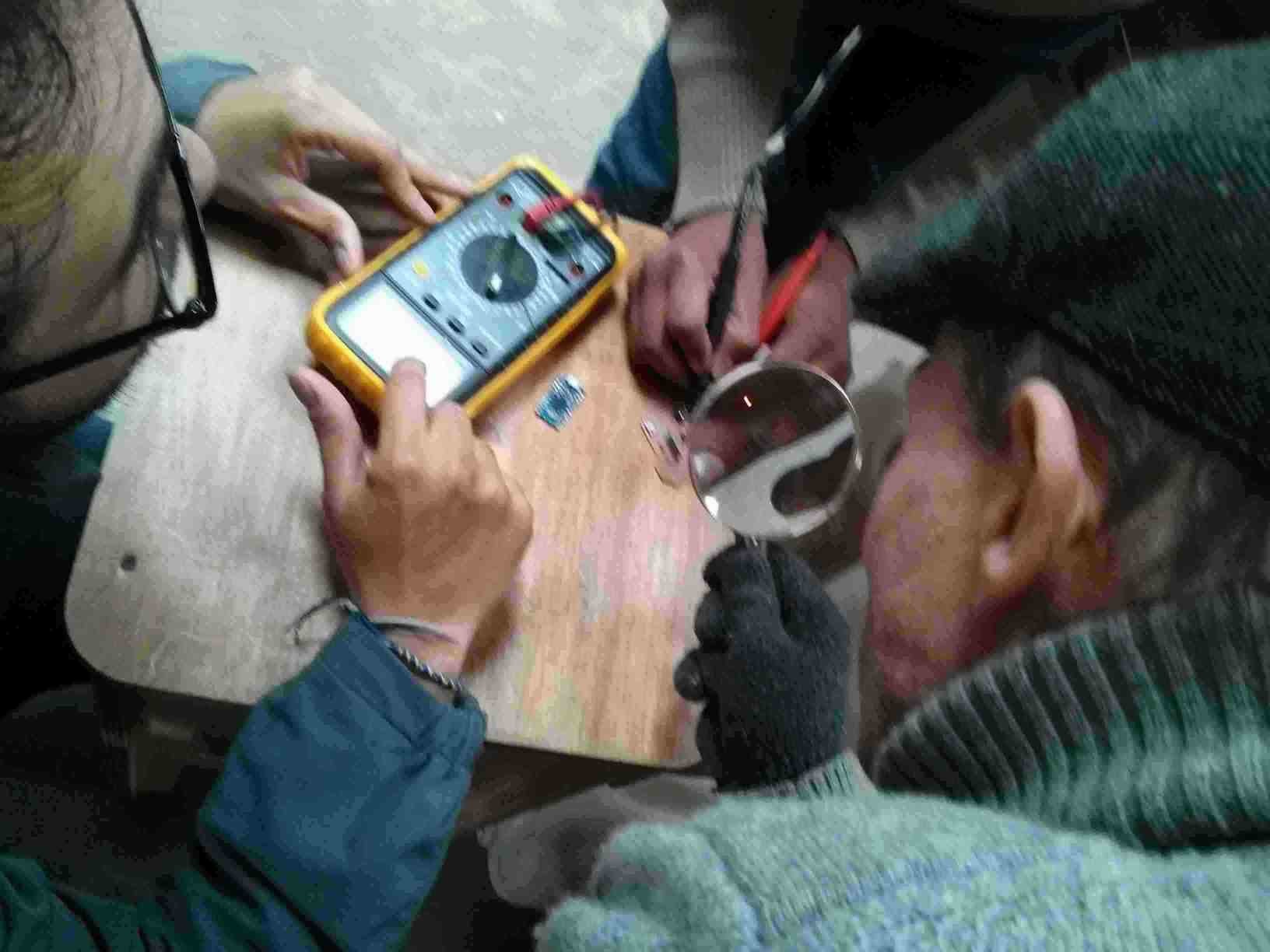
We can use up to 12 pins for input or output on the AVR AT Tiny 44 Micro-controller Unit. All pins can handle analog as well digital signals.
I have problems with the sizes of the traces. I thought the traces were thin because I used up to 5 offsets. But even when I use 1 offset, I have the same problem. I had to place wires in place of some of the traces. The only board I did not have this problem was with the ISP programmer. I did not modify that design. It is strange because even the Axis program in LinuxCNC that controls the mill, sees the tracks as wide. But they are milled thin. Perhaps it has to do with the quality of the endmill.
The cuts must not be on the edge of the image because Fabmodules will not consider them as lines to cut. The milling and cutting is done around the contrasting colors.