Harvard and Von Neumann architectures are the leading architectures for computers.
Von Neumann is more complex. But it does not require scheduling. Harvard is costly for making the Control Unit.
Information taken from here
Programming an AT Tiny 44 with a FabTinyISP via the Arduino IDE is possible when you connect the FabTinyISP to your computer's USB port and the AT Tiny 44 board to the FabTinyISP on the ISP port (sometimes named ICSP). It uses the i2c programming protocol.
It is possible to communicate to other boards via the FTDI port. It is used to communicate one MCU with another. Programming is only done through the ISP port.
These experiences are detailed below.
The AVR AT Tiny 44 MCU has 14 pins. 2 pins are used for Vcc and Gnd. It is capable of using 11 pins for inputs and outputs. It can even use the reset pin when setting its internal pull-up resistor, giving a total of 12 available pins. These pins are all capable of handling analog input or output signals. So they can also use digital signals. But with the Arduino IDE only 10 are available.
I have cut the Hello 44 + Inputs board and the Outputs board with a CNC mill. Then I have tested the ICs and their board connections by programming them via the FabISP firmware https://github.com/Academany/FabAcademany-Resources/blob/master/files/firmware_44.zip from the Electronic production Fab ISP_english tutorial page http://fabacademy.org/2018/docs/FabAcademy-Tutorials/week4_electronic_production/fabisp.html . I used that because it had the same IC as my boards. I took care to uncomment the line where the programmer is "usbtiny" and to comment the line where the programmer was "avrisp2" on the Makefile text.
I took the following steps:
      make clean
      make hex
      make fuse
      make program
The hello.ftdi.44 was the most similar to my board because I based my design on it. I tried installing this firmware by following his firmware compilation and installation tutorial photo.
Constructing the firmware .hex file:
      $ make -f hello.ftdi.44.echo.c.make
      avr-gcc -mmcu=attiny44 -Wall -Os -DF_CPU=20000000 -I./ -o hello.ftdi.44.echo.out hello.ftdi.44.echo.c
      avr-objcopy -O ihex hello.ftdi.44.echo.out hello.ftdi.44.echo.c.hex;\
      avr-size --mcu=attiny44 --format=avr hello.ftdi.44.echo.out
      AVR Memory Usage
      ----------------
      Device: attiny44

      Program:     760 bytes (18.6% Full)
      (.text + .data + .bootloader)

      Data:         64 bytes (25.0% Full)
      (.data + .bss + .noinit)
It was successful since it output no error.
Then I installed the firmware on the board:
      $ make -f hello.ftdi.44.echo.c.make program-usbtiny-fuses
      avr-objcopy -O ihex hello.ftdi.44.echo.out hello.ftdi.44.echo.c.hex;\
      avr-size --mcu=attiny44 --format=avr hello.ftdi.44.echo.out
      AVR Memory Usage
      ----------------
      Device: attiny44

      Program:     760 bytes (18.6% Full)
      (.text + .data + .bootloader)

      Data:         64 bytes (25.0% Full)
      (.data + .bss + .noinit)


      avrdude -p t44 -P usb -c usbtiny -U lfuse:w:0x5E:m
      avrdude: Error: Could not find USBtiny device (0x1781/0xc9f)

      avrdude done.  Thank you.

      hello.ftdi.44.echo.c.make:31: fallo en las instrucciones para el objetivo 'program-usbtiny-fuses'
      make: *** [program-usbtiny-fuses] Error 1
But the programmer and the board had not been plugged in. That is why I get an error.
After plugging in the programmer and the new board, programming is successful:
      $ make -f hello.ftdi.44.echo.c.make program-usbtiny-fuses
      avr-objcopy -O ihex hello.ftdi.44.echo.out hello.ftdi.44.echo.c.hex;\
      avr-size --mcu=attiny44 --format=avr hello.ftdi.44.echo.out
      AVR Memory Usage
      ----------------
      Device: attiny44

      Program:     760 bytes (18.6% Full)
      (.text + .data + .bootloader)

      Data:         64 bytes (25.0% Full)
      (.data + .bss + .noinit)


      avrdude -p t44 -P usb -c usbtiny -U lfuse:w:0x5E:m

      avrdude: AVR device initialized and ready to accept instructions

      Reading | ################################################## | 100% 0.01s

      avrdude: Device signature = 0x1e9207 (probably t44)
      avrdude: reading input file "0x5E"
      avrdude: writing lfuse (1 bytes):

      Writing | ################################################## | 100% 0.02s

      avrdude: 1 bytes of lfuse written
      avrdude: verifying lfuse memory against 0x5E:
      avrdude: load data lfuse data from input file 0x5E:
      avrdude: input file 0x5E contains 1 bytes
      avrdude: reading on-chip lfuse data:

      Reading | ################################################## | 100% 0.00s

      avrdude: verifying ...
      avrdude: 1 bytes of lfuse verified

      avrdude: safemode: Fuses OK (E:FF, H:DF, L:5E)

      avrdude done.  Thank you.
It worked. Now we will burn fuses:
      $ make -f hello.ftdi.44.echo.c.make program-usbtiny
      avr-objcopy -O ihex hello.ftdi.44.echo.out hello.ftdi.44.echo.c.hex;\
      avr-size --mcu=attiny44 --format=avr hello.ftdi.44.echo.out
      AVR Memory Usage
      ----------------
      Device: attiny44

      Program:     760 bytes (18.6% Full)
      (.text + .data + .bootloader)

      Data:         64 bytes (25.0% Full)
      (.data + .bss + .noinit)


      avrdude -p t44 -P usb -c usbtiny -U flash:w:hello.ftdi.44.echo.c.hex

      avrdude: AVR device initialized and ready to accept instructions

      Reading | ################################################## | 100% 0.01s

      avrdude: Device signature = 0x1e9207 (probably t44)
      avrdude: NOTE: "flash" memory has been specified, an erase cycle will be performed
      To disable this feature, specify the -D option.
      avrdude: erasing chip
      avrdude: reading input file "hello.ftdi.44.echo.c.hex"
      avrdude: input file hello.ftdi.44.echo.c.hex auto detected as Intel Hex
      avrdude: writing flash (760 bytes):

      Writing | ################################################## | 100% 2.05s

      avrdude: 760 bytes of flash written
      avrdude: verifying flash memory against hello.ftdi.44.echo.c.hex:
      avrdude: load data flash data from input file hello.ftdi.44.echo.c.hex:
      avrdude: input file hello.ftdi.44.echo.c.hex auto detected as Intel Hex
      avrdude: input file hello.ftdi.44.echo.c.hex contains 760 bytes
      avrdude: reading on-chip flash data:

      Reading | ################################################## | 100% 2.69s

      avrdude: verifying ...
      avrdude: 760 bytes of flash verified

      avrdude: safemode: Fuses OK (E:FF, H:DF, L:5E)

      avrdude done.  Thank you.
The program is installed in my board. But this program does not use the new components I added to my board. I must study how to add the new pin functions.
Now it was time to modify an existing program to work with my boards. I was reading several C programs from Neil Gerschenfield's boards. But I cannot see what pins he assigned to which functions.
I will test with a program that will show the results of my input device: the phototransistor. So I test with a modified version of Neil's light detector for AT Tiny 45.
In the phototransistor C program I changed PORTB to PORTA, DDRB to DDRA and PB2 to PA2 (considering the pins that connected the light detector in the original design and the new one).
This is my phototransistor makefile where I changed PROJECT from hello.photo.45 to hello.photo.44 , changed SOURCES from attiny45 to attiny44 and changed all incidences of t45 to t44:
      PROJECT=hello.photo.44
      SOURCES=$(PROJECT).c
      MMCU=attiny44
      F_CPU = 8000000

      CFLAGS=-mmcu=$(MMCU) -Wall -Os -DF_CPU=$(F_CPU)

      $(PROJECT).hex: $(PROJECT).out
      avr-objcopy -O ihex $(PROJECT).out $(PROJECT).c.hex;\
      avr-size --mcu=$(MMCU) --format=avr $(PROJECT).out

      $(PROJECT).out: $(SOURCES)
      avr-gcc $(CFLAGS) -I./ -o $(PROJECT).out $(SOURCES)

      program-bsd: $(PROJECT).hex
      avrdude -p t44 -c bsd -U flash:w:$(PROJECT).c.hex

      program-dasa: $(PROJECT).hex
      avrdude -p t44 -P /dev/ttyUSB0 -c dasa -U flash:w:$(PROJECT).c.hex

      program-avrisp2: $(PROJECT).hex
      avrdude -p t44 -P usb -c avrisp2 -U flash:w:$(PROJECT).c.hex

      program-usbtiny: $(PROJECT).hex
      avrdude -p t44 -P usb -c usbtiny -U flash:w:$(PROJECT).c.hex

      program-dragon: $(PROJECT).hex
      avrdude -p t44 -P usb -c dragon_isp -U flash:w:$(PROJECT).c.hex

      program-ice: $(PROJECT).hex
      avrdude -p t44 -P usb -c atmelice_isp -U flash:w:$(PROJECT).c.hex
I ran make. But there is an error:
      $ make -f hello.photo.44.make
      avr-gcc -mmcu=attiny44 -Wall -Os -DF_CPU=8000000 -I./ -o hello.photo.44.out hello.photo.44.c
      hello.photo.44.c: In function ‘main’:
      hello.photo.44.c:120:18: error: ‘REFS2’ undeclared (first use in this function)
      ADMUX = (0 << REFS2) | (0 << REFS1) | (0 << REFS0) // Vcc ref
						  ^
      hello.photo.44.c:120:18: note: each undeclared identifier is reported only once for each function it appears in
      hello.photo.44.make:13: recipe for target 'hello.photo.44.out' failed
      make: *** [hello.photo.44.out] Error 1
The program is designed for the AT Tiny 45. Possibly this is the reason these functions will not work in the AT Tiny 44. So I commented out (with double slash) the lines when they reported errors. These were the lines.
      //ADMUX = (0 << REFS2) | (0 << REFS1) | (0 << REFS0) // Vcc ref
      //   | (0 << ADLAR) // right adjust
      //   | (0 << MUX3) | (0 << MUX2) | (1 << MUX1) | (1 << MUX0); // ADC3
      //ADCSRA = (1 << ADEN) // enable
      //   | (1 << ADPS2) | (1 << ADPS1) | (1 << ADPS0); // prescaler /128
The command did not report any errors thereafter. Then i ran make again.
      $ make -f hello.photo.44.make
      avr-gcc -mmcu=attiny44 -Wall -Os -DF_CPU=8000000 -I./ -o hello.photo.44.out hello.photo.44.c
      avr-objcopy -O ihex hello.photo.44.out hello.photo.44.c.hex;\
      avr-size --mcu=attiny44 --format=avr hello.photo.44.out
      AVR Memory Usage
      ----------------
      Device: attiny44

      Program:     496 bytes (12.1% Full)
      (.text + .data + .bootloader)

      Data:          1 bytes (0.4% Full)
      (.data + .bss + .noinit)
No errors, so I proceeded to program the processor and blow the fuses.
      $ make -f hello.photo.44.make program-usbtiny
      avr-objcopy -O ihex hello.photo.44.out hello.photo.44.c.hex;\
      avr-size --mcu=attiny44 --format=avr hello.photo.44.out
      AVR Memory Usage
      ----------------
      Device: attiny44

      Program:     496 bytes (12.1% Full)
      (.text + .data + .bootloader)

      Data:          1 bytes (0.4% Full)
      (.data + .bss + .noinit)


      avrdude -p t44 -P usb -c usbtiny -U flash:w:hello.photo.44.c.hex

      avrdude: AVR device initialized and ready to accept instructions

      Reading | ################################################## | 100% 0.01s

      avrdude: Device signature = 0x1e9207 (probably t44)
      avrdude: NOTE: "flash" memory has been specified, an erase cycle will be performed
      To disable this feature, specify the -D option.
      avrdude: erasing chip
      avrdude: reading input file "hello.photo.44.c.hex"
      avrdude: input file hello.photo.44.c.hex auto detected as Intel Hex
      avrdude: writing flash (496 bytes):

      Writing | ################################################## | 100% 0.35s

      avrdude: 496 bytes of flash written
      avrdude: verifying flash memory against hello.photo.44.c.hex:
      avrdude: load data flash data from input file hello.photo.44.c.hex:
      avrdude: input file hello.photo.44.c.hex auto detected as Intel Hex
      avrdude: input file hello.photo.44.c.hex contains 496 bytes
      avrdude: reading on-chip flash data:

      Reading | ################################################## | 100% 0.54s

      avrdude: verifying ...
      avrdude: 496 bytes of flash verified

      avrdude: safemode: Fuses OK (E:FF, H:DF, L:5E)

      avrdude done.  Thank you.
The only difference between the commands on hello.44.ftdi and hello.44.photo is:
avrdude -p t44 -P usb -c usbtiny -U lfuse:w:0x5E:m
on the former and:
avrdude -p t44 -P usb -c usbtiny -U flash:w:hello.photo.44.c.hex
on the later.
I tried programming with Arduino IDE instructions from Alex Tocagon and Arduino IDE instructions from Andrés Moreno. But their instructions are valid for another version of Arduino IDE. They expected to have a place to provide the URL for FabtinyISP configuration files for the Arduino IDE.
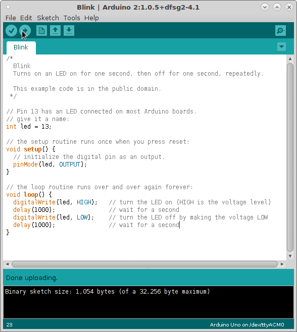
I initially have been able to program the Arduino UNO to blink a LED. So I installed the Arduino IDE.
sudo apt-get install arduino
Then open the Arduino IDE and select the board you are using.
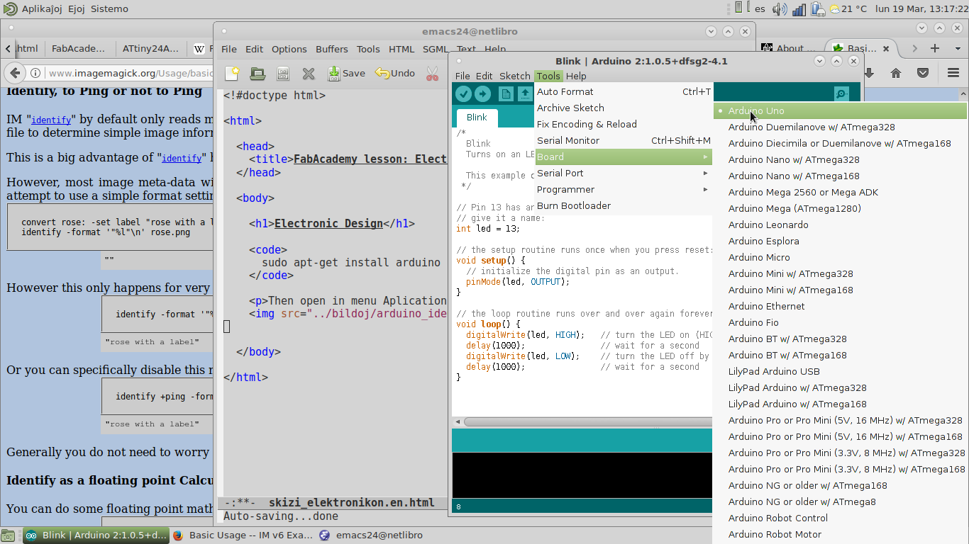
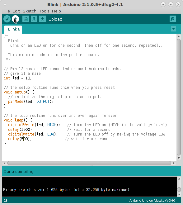
This program blinks the Arduino UNO LED at one second and half a second intervals.
Datasheet shows the pinout for Arduino UNO's ATMel 328p
The pinout for one board is different from the pinout on another. The pinout on Arduino is not necessarily the same numbering as the ATMel numbering.
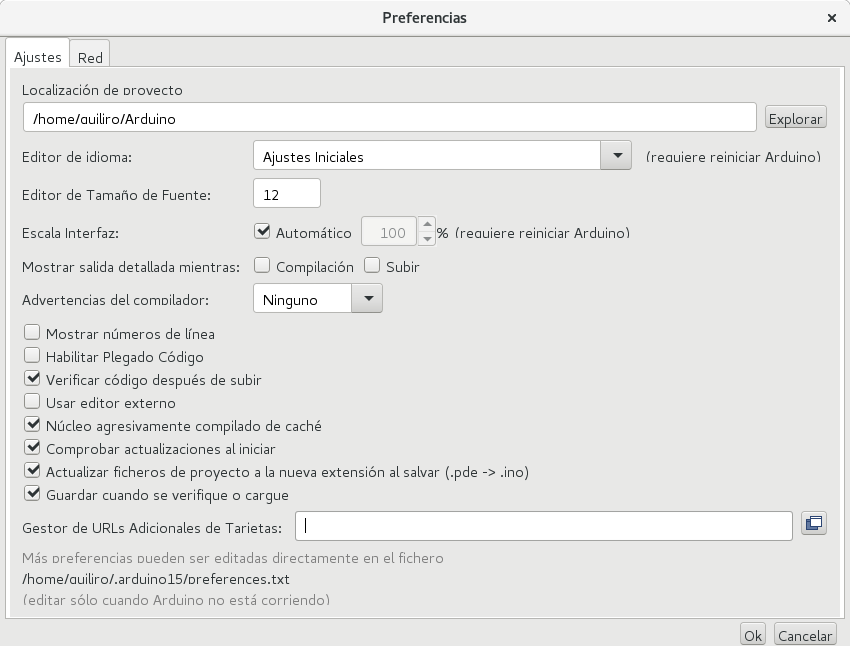
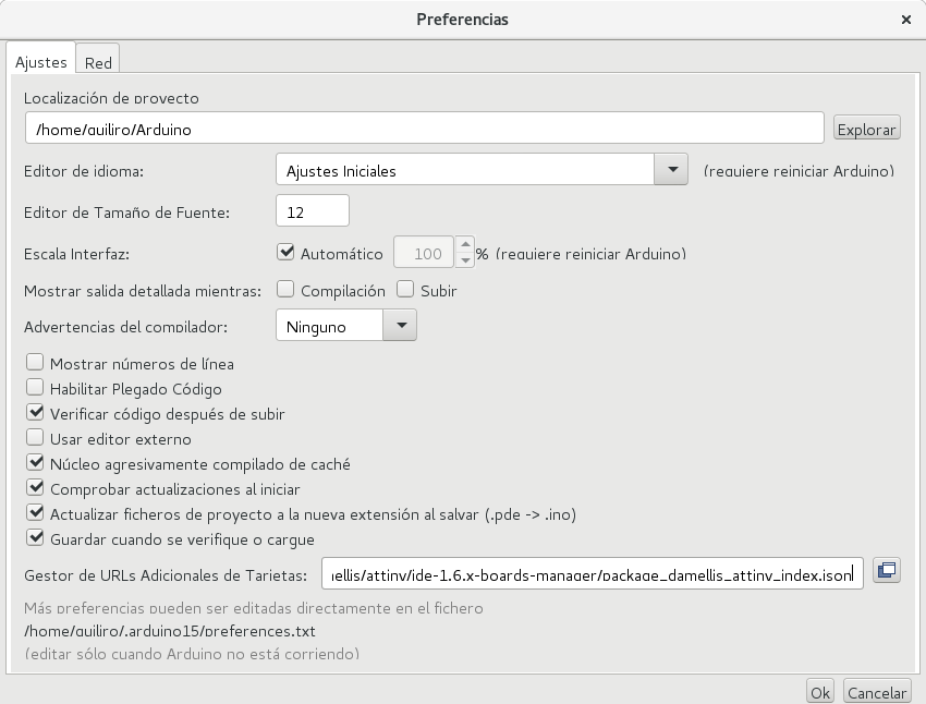
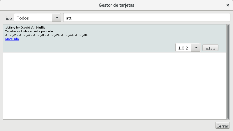
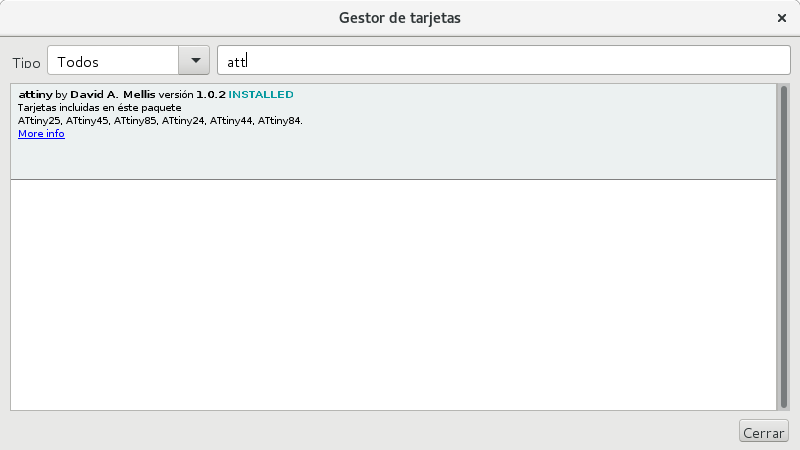
I could install the library to program through the FabtinyISP via de Arduino IDE by downloading a newer version from the Arduino website. It provided the appropriate space to paste the URL taking from a list of third party libraries refered at the Arduino web site.
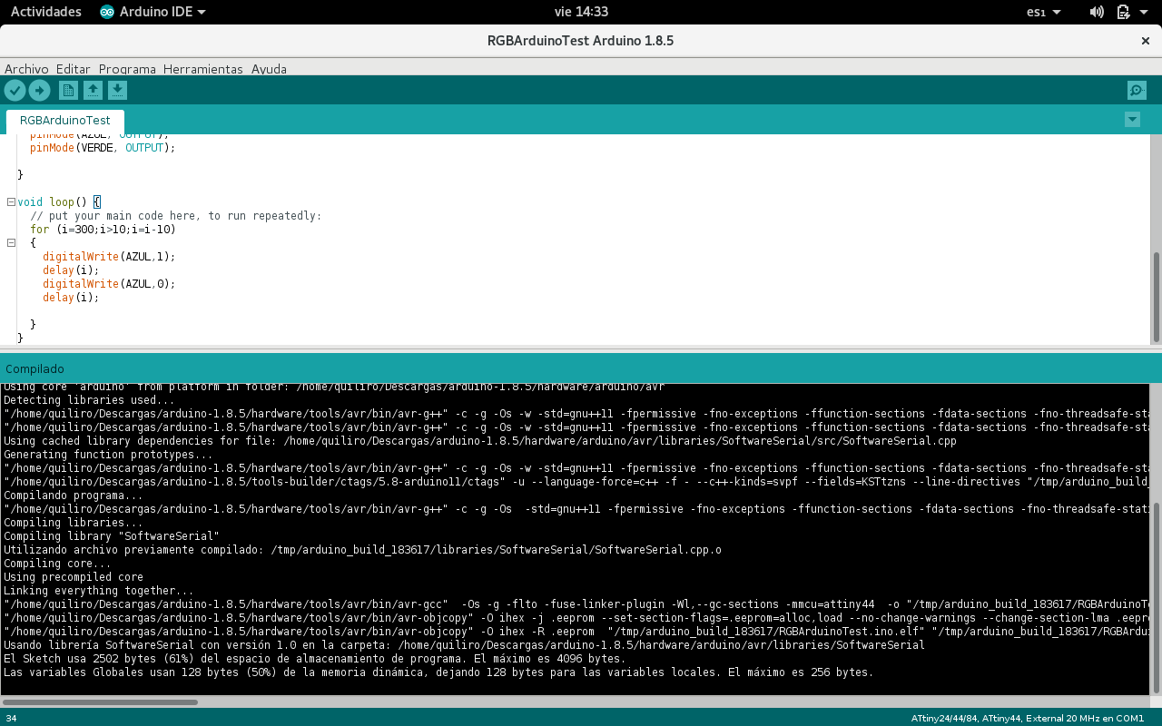
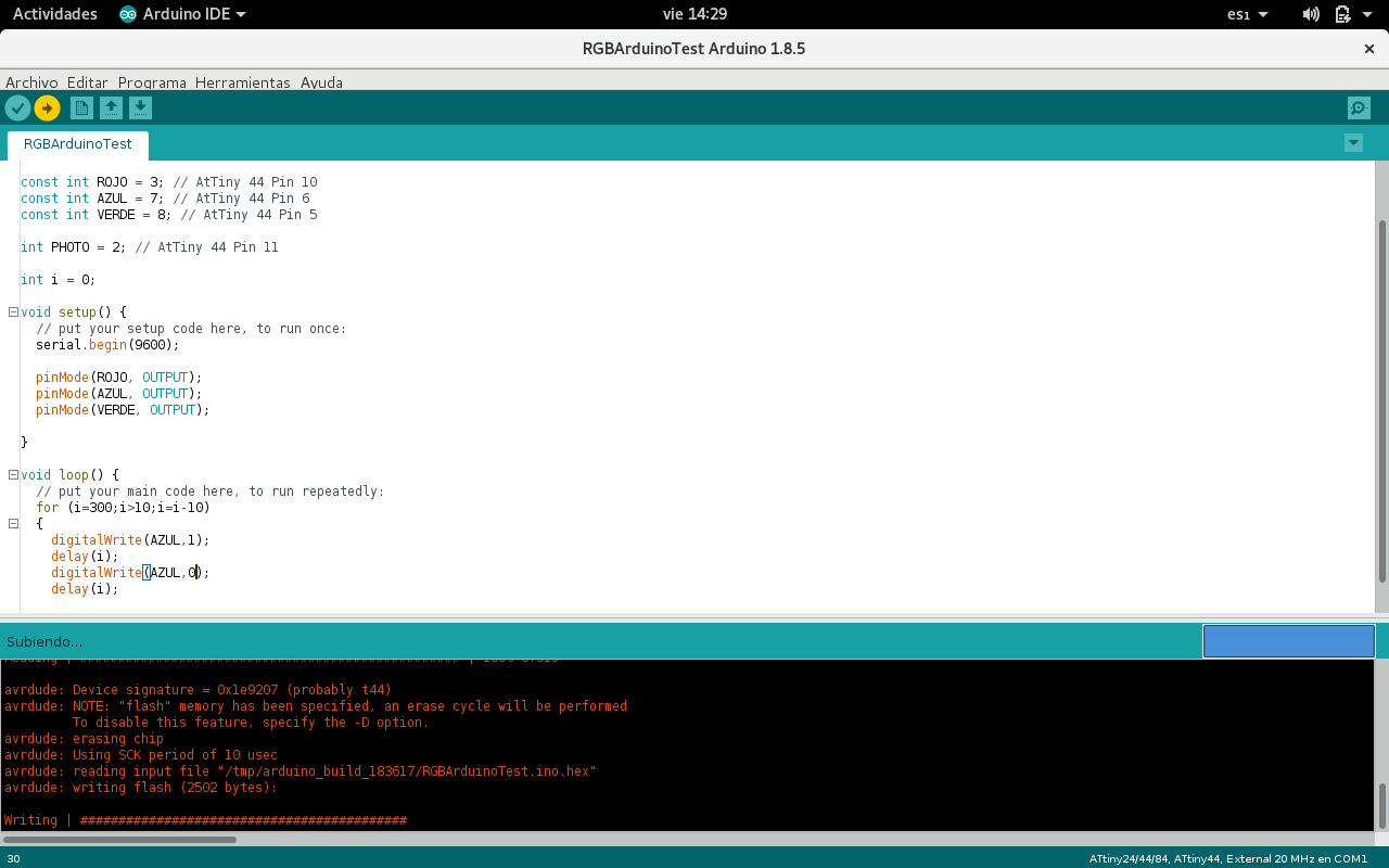
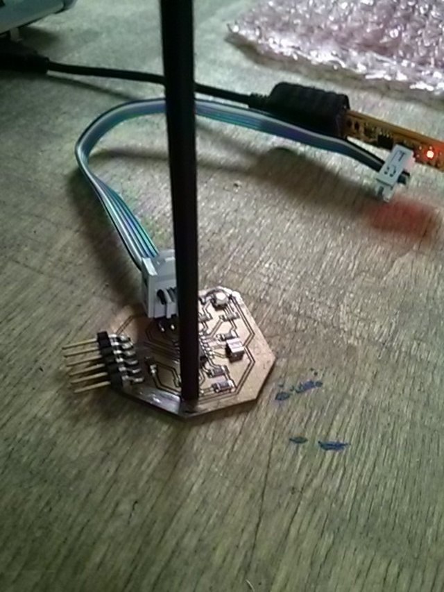
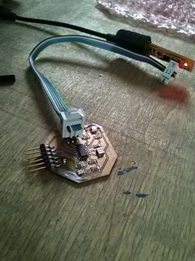
I then proceeded to use the Arduino IDE to program my boards via my FabTinyISP.
Compiling the program:
Writing:
Verifying the written program:
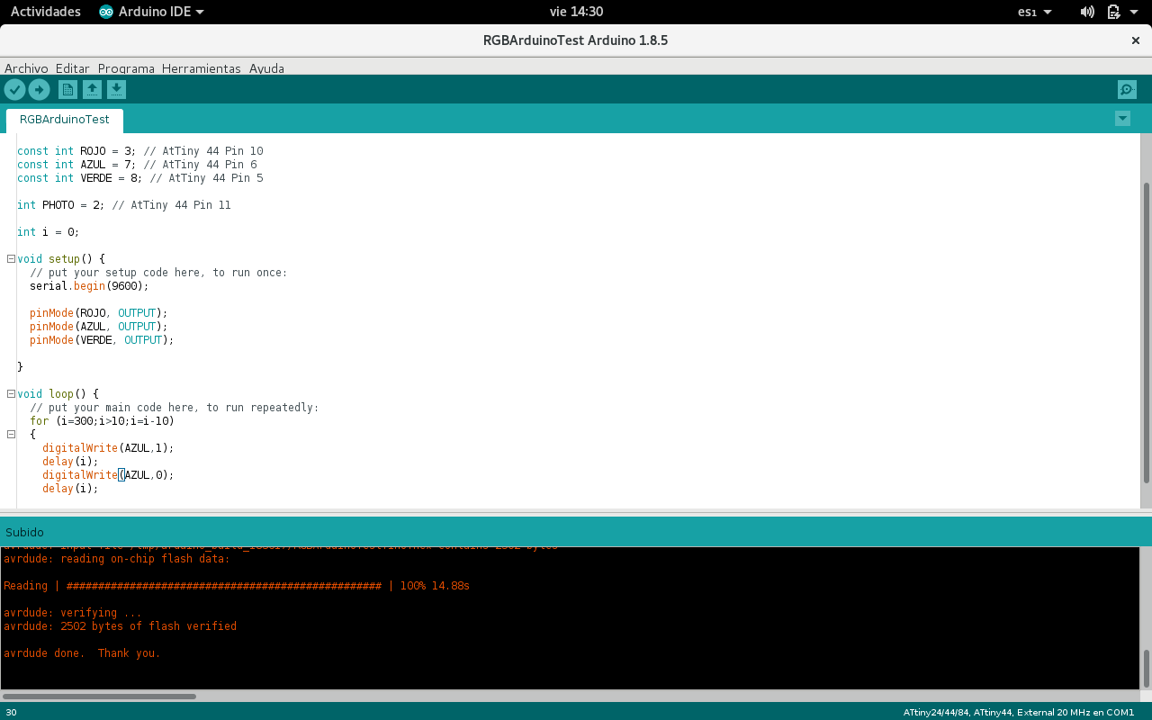
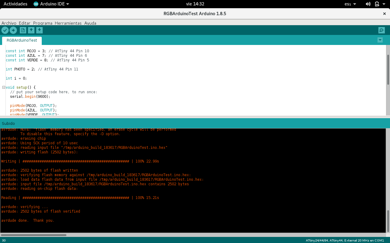
The whole process of erasing, writing and verifying the program with Arduino IDE via FabTinyISP:
I wrote an Arduino macro which understands the AT Tiny 44 pin numbering and feeds it to the Arduino IDE, which handles a different pin numbering system.
      // Copyright 2018 Quiliro Ordóñez under the GNU General Public License version 3
      // or later as published by the Free Software Foundation https://fsf.org

      #include <SoftwareSerial.h>

      // Arduino to AtTiny44 Pinouts:
                        // Arduino Vcc, AtTiny 44 Pin 14
      const int T13 = 0; // Arduino 0, AtTiny 44 Pin 13 (0+13=13)
      const int T12 = 1; // Arduino 1, AtTiny 44 Pin 12 (1+12=13)
      const int T11 = 2; // Arduino 2, AtTiny 44 Pin 11 (2+11=13)
      const int T10 = 3; // Arduino 3, AtTiny 44 Pin 10 (3+10=13)
      const int T9 = 4;  // Arduino 4, AtTiny 44 Pin 9 (4+9=13)
      const int T8 = 5;  // Arduino 5, AtTiny 44 Pin 8 (5+8=13)
      const int T7 = 6;  // Arduino 6, AtTiny 44 Pin 7 (6+7=13)
      const int T6 = 7;  // Arduino 7, AtTiny 44 Pin 6 (7+6=13)
      const int T5 = 8;  // Arduino 8, AtTiny 44 Pin 5 (8+5=13)
                         // Arduino pin not available for AtTiny 44 Pin 04
      const int T3 = 9;  // Arduino 9, AtTiny 44 Pin 3 (9+3=12)
      const int T2 = 10; // Arduino 10, AtTiny 44 Pin 2 (10+2=12)
                         // Arduino Gnd, AtTiny 44 Pin 1
All that is needed to use this macro is to use labels T2 thru T13 for the AT Tiny 44 pins with the corresponding numbers as described above.
I programmed the MCU to produce 7 colors sequentially with the RGB LED.
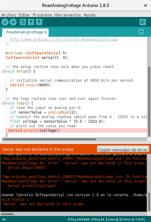
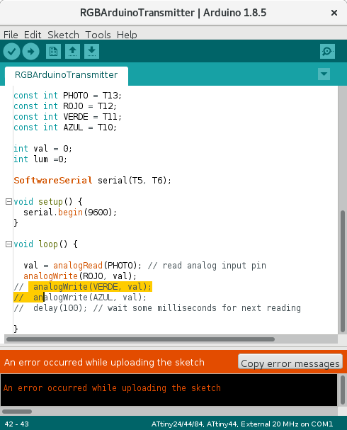
My first tests with Arduino IDE trying to find the correct pins.
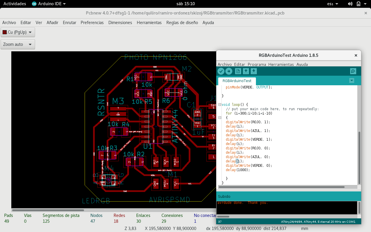
With this AT Tiny 44 to Arduino pinout macro, I could manage to blink the output device board RGB LEDs in ever increasing speed through the seven possible colours by combining the 3 LEDs in different ways:
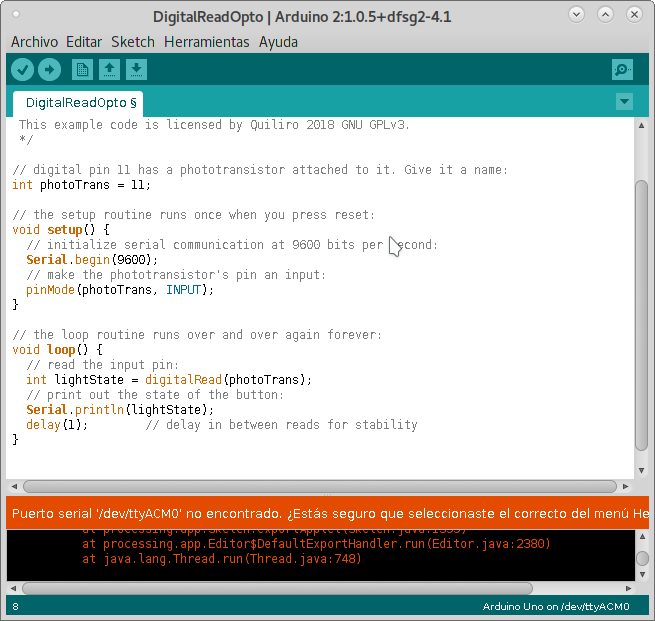
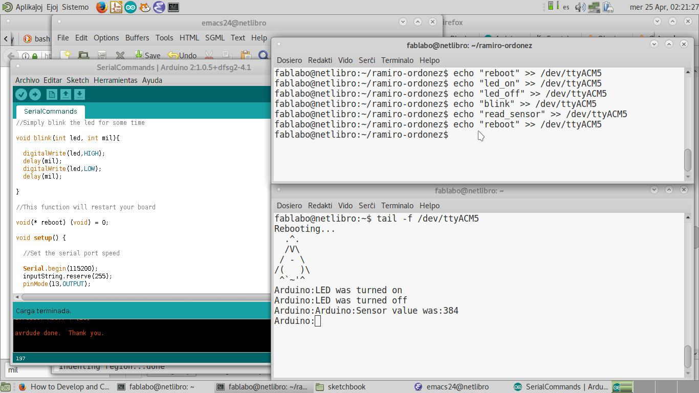
In order to show the detection of light, the MCU must send a signal showing what values the phototransistor is sensing. The easiest method to show this is the incorporated RGB LED. It glows more when the phototransistor is exposed and less when the phototransistor is shielded from ambient light. The Arduino IDE Light intensity sensor program is used to make this happen.
Covering the phototransistor with a staw because the light detection capability of the phototransistor is very high. It is not noticeable but the LED is off on the first image and lit on the second image.
The LEDs do get more brightness with more voltage. I do not need that. All I need is binary data: on or off in a sequence. So I made a program to blink the LEDs on one board at a certain sequence. The other board would detect this light and blink its LEDs at the same sequence. But the program which blinks the LEDs in a binary sequence and the program which detects that blinking sequence is described on the Networking week.
      $ python term.py /dev/ttyUSB0 115200
      Traceback (most recent call last):
      File "term.py", line 19, in
	from Tkinter import *
      File "/usr/lib/python2.7/lib-tk/Tkinter.py", line 42, in
	raise ImportError, str(msg) + ', please install the python-tk package'
	ImportError: No module named _tkinter, please install the python-tk package
But a dependency is missing. I proceed to install it:
      $ sudo apt install python-tk
      Leyendo lista de paquetes... Hecho
      Creando árbol de dependencias
      Leyendo la información de estado... Hecho
      Se instalarán los siguientes paquetes adicionales:
      blt libtcl8.6 libtk8.6 tk8.6-blt2.5
      Paquetes sugeridos:
      blt-demo tcl8.6 tk8.6 tix python-tk-dbg
      Se instalarán los siguientes paquetes NUEVOS:
      blt libtcl8.6 libtk8.6 python-tk tk8.6-blt2.5
      0 actualizados, 5 nuevos se instalarán, 0 para eliminar y 541 no actualizados.
      Se necesita descargar 2.369 kB de archivos.
      Se utilizarán 8.679 kB de espacio de disco adicional después de esta operación.
      ¿Desea continuar? [S/n]
      Des:1 http://http.us.debian.org/debian sid/main amd64 libtcl8.6 amd64 8.6.8+dfsg-4 [988 kB]
      Des:2 http://http.us.debian.org/debian sid/main amd64 libtk8.6 amd64 8.6.8-4 [752 kB]
      Des:3 http://http.us.debian.org/debian sid/main amd64 tk8.6-blt2.5 amd64 2.5.3+dfsg-4 [587 kB]
      Des:4 http://http.us.debian.org/debian sid/main amd64 blt amd64 2.5.3+dfsg-4 [14,8 kB]
      Des:5 http://http.us.debian.org/debian sid/main amd64 python-tk amd64 2.7.15~rc1-1 [27,2 kB]
      Descargados 2.369 kB en 5s (478 kB/s)
      Seleccionando el paquete libtcl8.6:amd64 previamente no seleccionado.
      (Leyendo la base de datos ... 196554 ficheros o directorios instalados actualmente.)
      Preparando para desempaquetar .../libtcl8.6_8.6.8+dfsg-4_amd64.deb ...
      Desempaquetando libtcl8.6:amd64 (8.6.8+dfsg-4) ...
      Seleccionando el paquete libtk8.6:amd64 previamente no seleccionado.
      Preparando para desempaquetar .../libtk8.6_8.6.8-4_amd64.deb ...
      Desempaquetando libtk8.6:amd64 (8.6.8-4) ...
      Seleccionando el paquete tk8.6-blt2.5 previamente no seleccionado.
      Preparando para desempaquetar .../tk8.6-blt2.5_2.5.3+dfsg-4_amd64.deb ...
      Desempaquetando tk8.6-blt2.5 (2.5.3+dfsg-4) ...
      Seleccionando el paquete blt previamente no seleccionado.
      Preparando para desempaquetar .../blt_2.5.3+dfsg-4_amd64.deb ...
      Desempaquetando blt (2.5.3+dfsg-4) ...
      Seleccionando el paquete python-tk previamente no seleccionado.
      Preparando para desempaquetar .../python-tk_2.7.15~rc1-1_amd64.deb ...
      Desempaquetando python-tk (2.7.15~rc1-1) ...
      Procesando disparadores para libc-bin (2.27-2) ...
      Configurando libtcl8.6:amd64 (8.6.8+dfsg-4) ...
      Configurando libtk8.6:amd64 (8.6.8-4) ...
      Configurando tk8.6-blt2.5 (2.5.3+dfsg-4) ...
      Configurando blt (2.5.3+dfsg-4) ...
      Configurando python-tk (2.7.15~rc1-1) ...
      Procesando disparadores para libc-bin (2.27-2) ...
Now to try to communicate with the port again:
      $ python term.py /dev/ttyUSB0 115200
      Traceback (most recent call last):
      File "term.py", line 92, in
	ser = serial.Serial(port,speed)
	File "/usr/lib/python2.7/dist-packages/serial/serialutil.py", line 240, in __init__
	self.open()
	File "/usr/lib/python2.7/dist-packages/serial/serialposix.py", line 268, in open
	raise SerialException(msg.errno, "could not open port {}: {}".format(self._port, msg))
	serial.serialutil.SerialException: [Errno 13] could not open port /dev/ttyUSB0: [Errno 13] Permission denied: '/dev/ttyUSB0'
This says the program could not open the port. And with root privileges it would not find the correct display device:
      $ sudo python term.py /dev/ttyUSB0 115200
      No protocol specified
      No protocol specified
      Traceback (most recent call last):
      File "term.py", line 102, in
	root = Tk()
      File "/usr/lib/python2.7/lib-tk/Tkinter.py", line 1822, in __init__
	self.tk = _tkinter.create(screenName, baseName, className, interactive, wantobjects, useTk, sync, use)
	_tkinter.TclError: couldn't connect to display ":0"
The problem is that the port is incorrectly defined since /dev/ttyUSB0 does not exist. No new file is created when plugging the USBtinyISP in the port. So with sudo it would be the same. There is no point in testing with minicom.
Testing Arduino UNO board with minicom is successful because it does create the port even if Arduino IDE shows serial port selection grayed out.
Arduino IDE does not detect the FabISP as a port. So it cannot upload the program to the board. This is a screenshot of the Arduino IDE without the USBtinyISP libraries installed.
But after installing the newer version of Arduino and the appropriate libraries, it was able to upload 2 different programs to each of the 2 boards with different configurations.
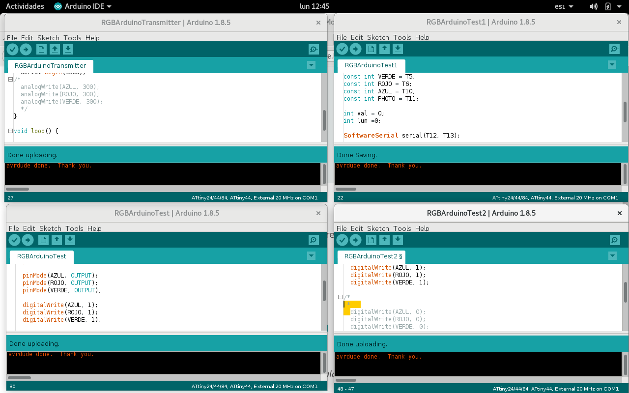
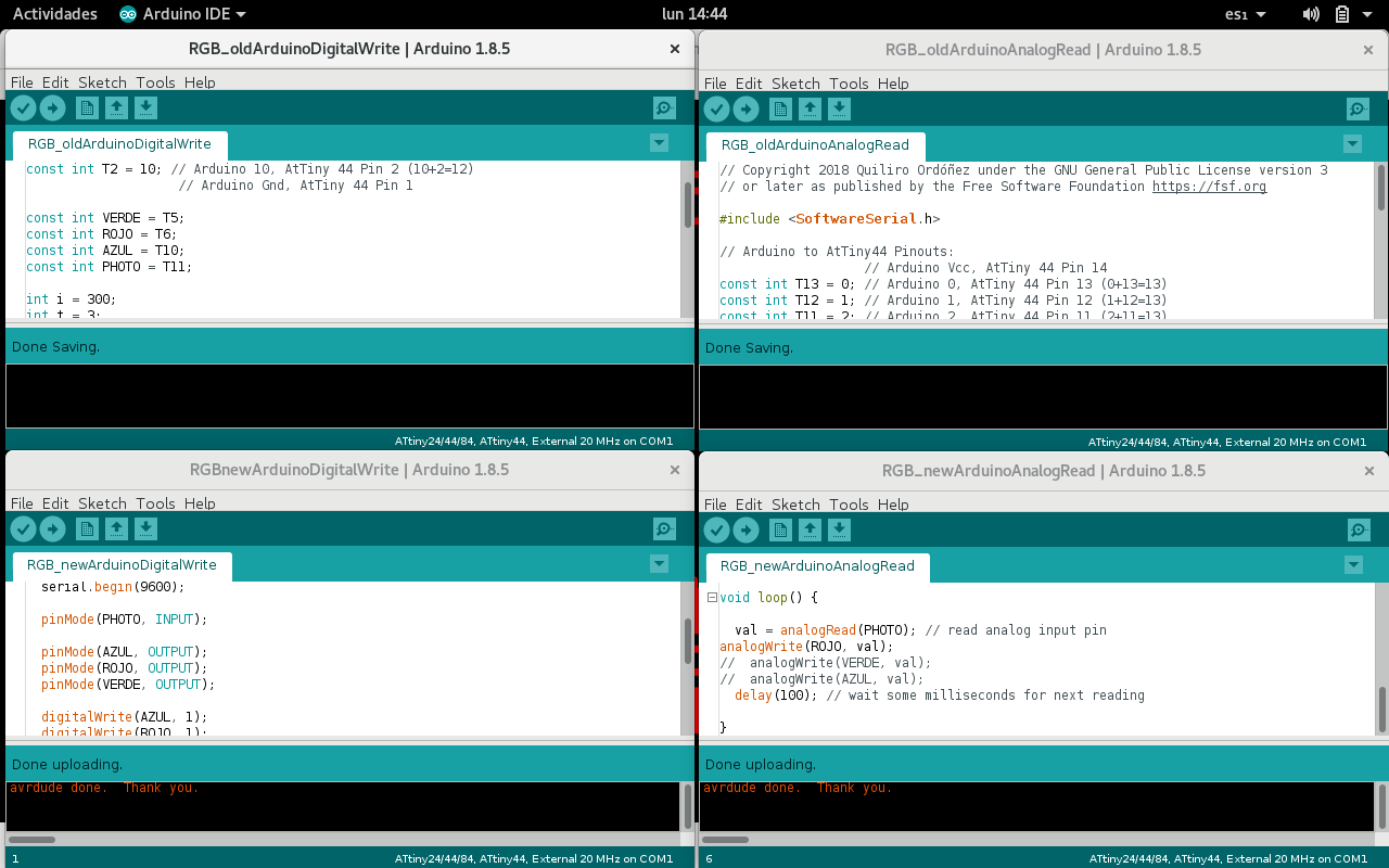
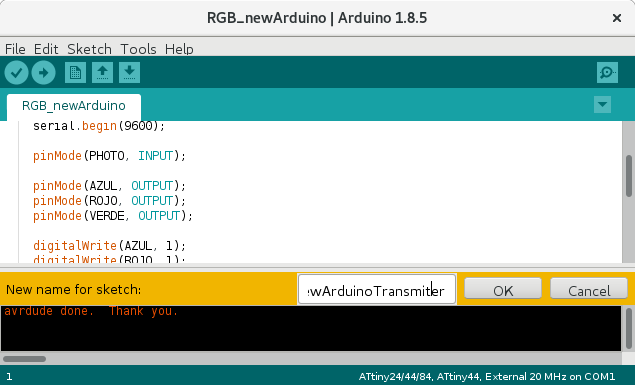
Renaming the programs is done by changing the tabs' names.
It is probably not too difficult to program in C once you have used the Arduino IDE. Just copy the the macros that your program uses from the libraries. Start with the simple examples that are already available.
Programming with Arduino IDE can be done even without having an Arduino board.
Arduino IDE is C language with some macros. If you can read the macros, then you can include the part that you need and avoid the bloat that is generated. You can even use the C you generate then to program directly with AVRDuDe.
Embedded programming can be reduced to 3 tasks: taking input, analize data, sending output. Once you understand this, motivation for programming is kindled.
AVRDude is not difficult to understand. You must memorize the command options or save them for default use.