In this lesson I design and fabricate a PCB with a light sensor which reads the intensity of light and glows a LED proportionately. I used KiCAD electronic design automation (EDA) libre software.
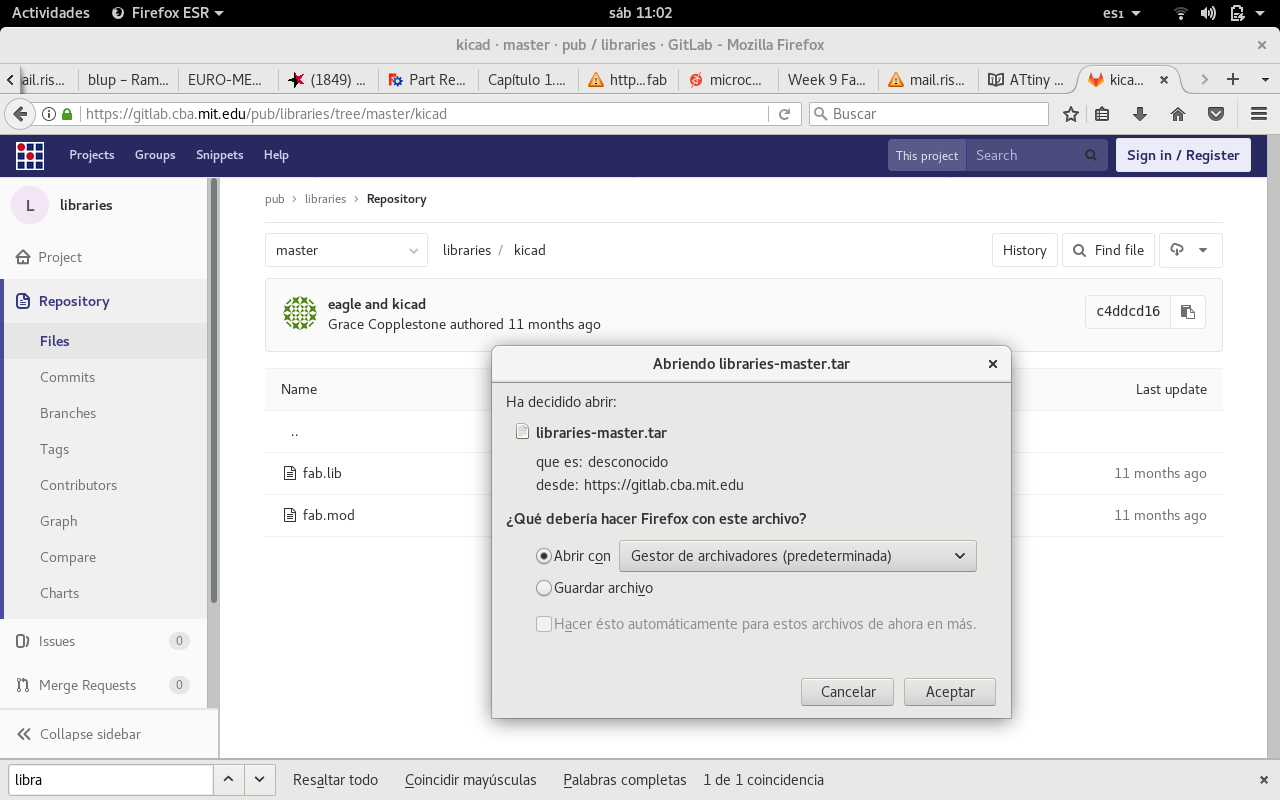
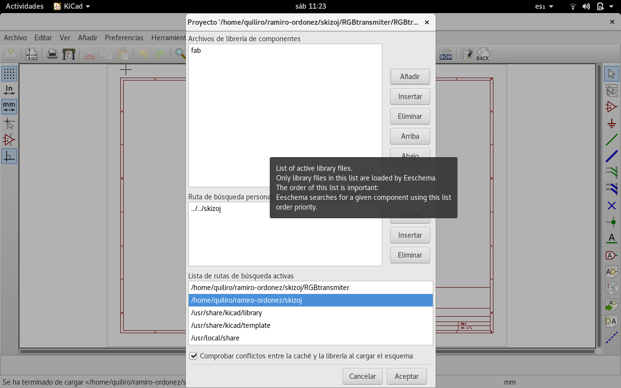
I have had trouble constructing the Hello World board because I did not load the updated fab libraries to KiCAD. So now I am loading them from Emanuele Goldoni's Hello World with KiCAD tutorial. And then I have added my input device: an opto electric sensor (phototransistor).
The first thing I needed to do was importing the component libraries from Emanuele Goldoni (pretty, mod and lib). As Emanuele sugests:
Before importing the library, add the 3D model of the resonator (a Ceramic Abracon AWSCR made by Walter Lain and released under CC3-BY-SA / GPL3) into the KiCad 3d packages folder.
Extract the resonator_SMD.* files somewhere, move within this folder and from a Terminal type
sudo cp resonator_SMD.wrl /usr/share/kicad/modules/packages3d/Crystals.3dshapes/sudo cp resonator_SMD.wings /usr/share/kicad/modules/packages3d/Crystals.3dshapes/Then add the fab.pretty library from Emanuele Goldoni into the Pcbnew path.
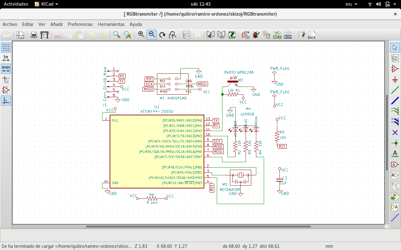
This is my first design where I put a common ground to the RGB LED anode. I had to break this connection and link it to Vcc on the board.
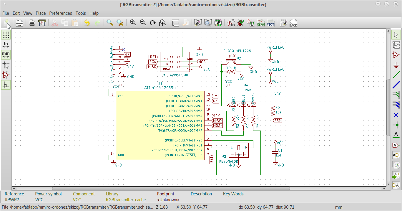
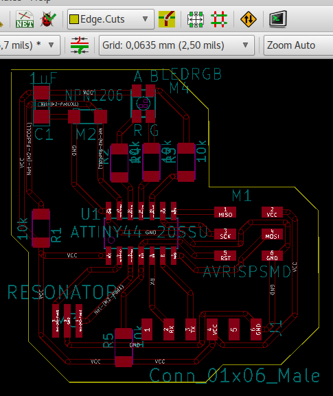
The corrected design has Vcc on the RGB LED common anode.
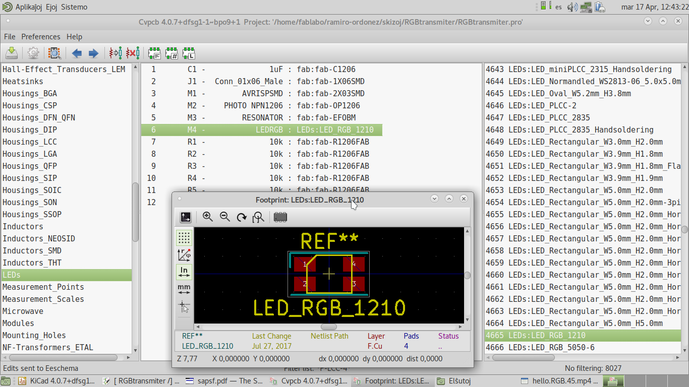
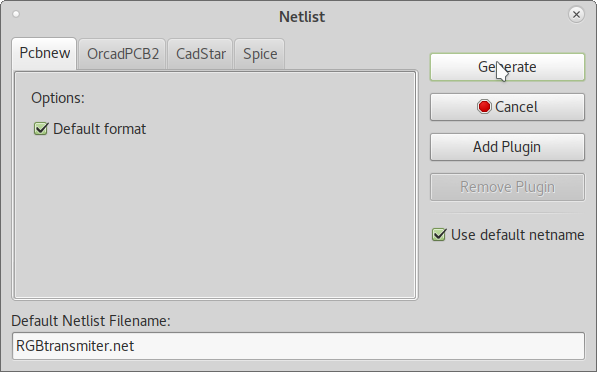
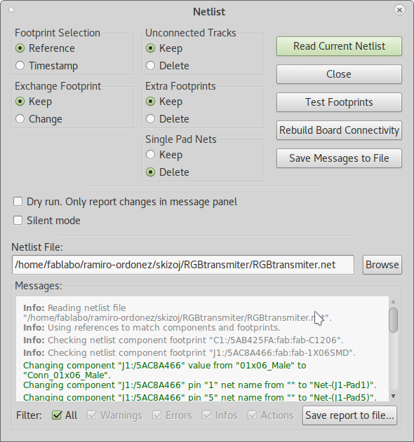
First read the netlist
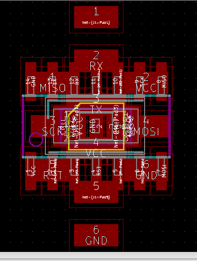
It sets the components in the middle of the design space.
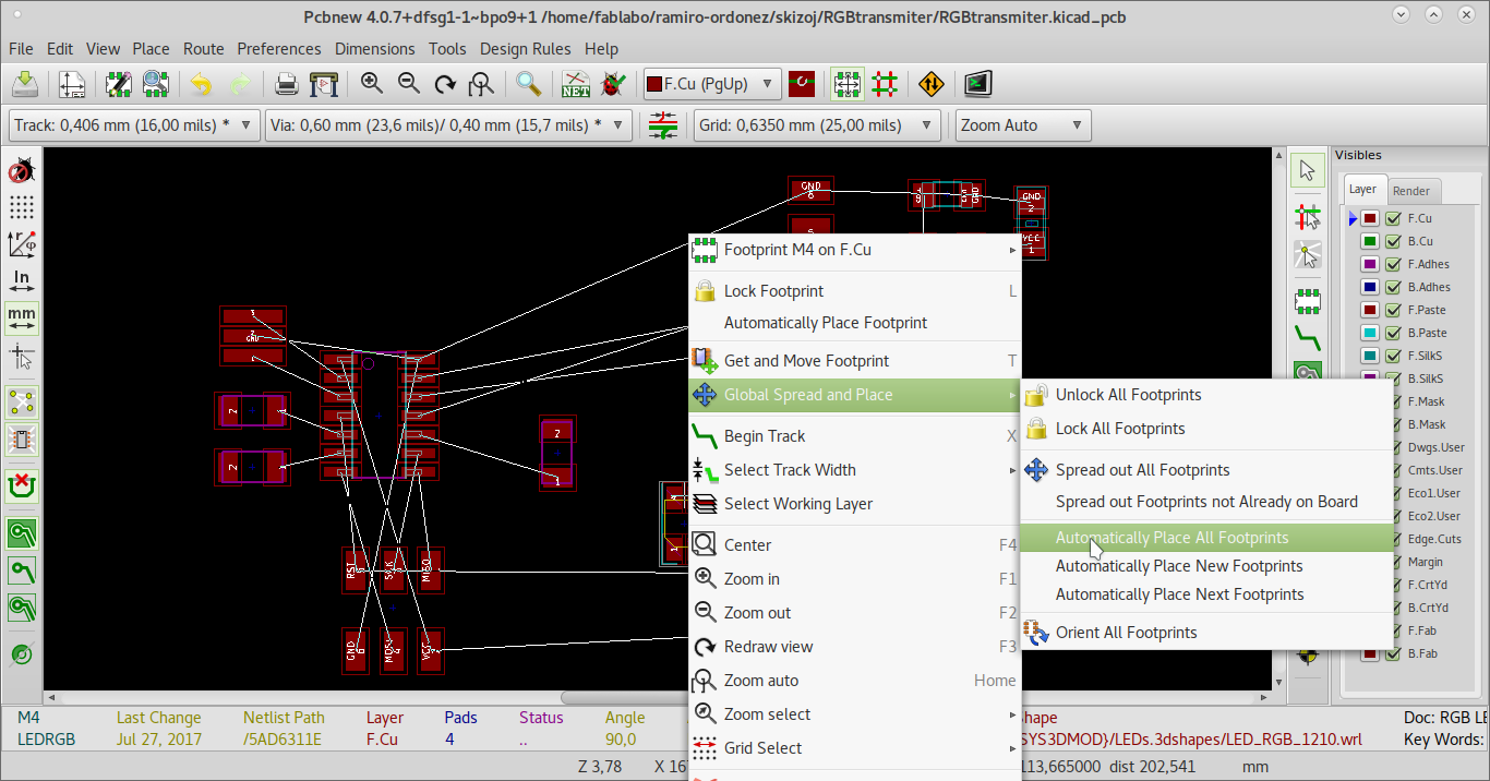
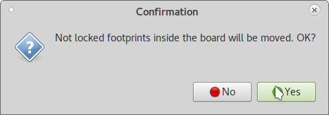
I try to use the feature for automatic distribution of components.
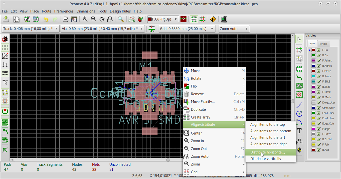
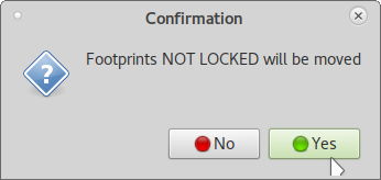
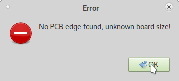
But it needs the board cuts (which I did not trace yet) in order to do it. Then I tryed spreading out the footprints.
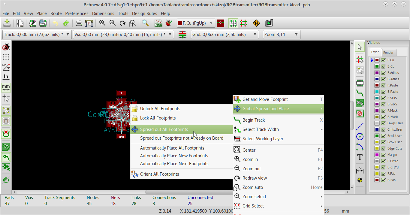
It did not work either. So I just placed the components, traces and cuts manually.
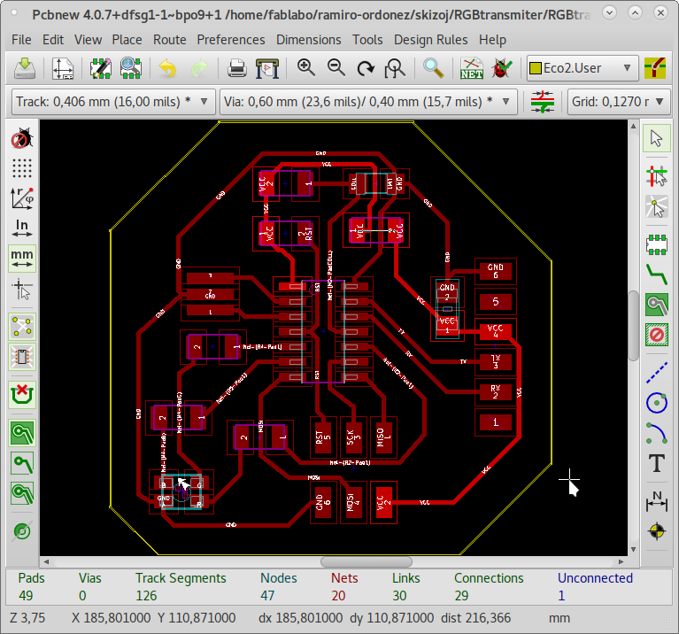
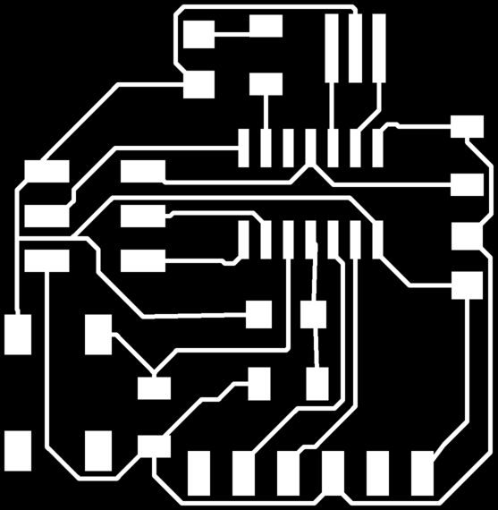
This is the corrected circuit design image which I used on the output device lesson.
I have discovered a software in order to make the gcode locally. There is a pcb2code tutorial.
I used the same command except for the drill, which is not necesary.
pcb2gcode \
      --zero-start \
      --onedrill \
      --software linuxcnc \
      --tile-x 1 \
      --tile-y 1 \
      --front *-F.Cu.g* \
      --back *-B.Cu.g* \
      --front-output front.ngc \
      --back-output back.ngc \
      --metric \
      --zwork 0 --offset 0.2 \
      --zsafe 3 --zchange 40 \
      --mill-feed 500 \
      --mill-speed 6000 \
      --zdrill -3 \
      --drill-feed 500 \
      --drill-speed 6000
I had an error because I have not generated Gerber files. Besides, some of the parameters (such as --zero-start) are obsolete. Finally, I ran a reduced set without drilling:
pcb2gcode \
      --front *-F.Cu.g* \
      --front-output front.ngc \
      --metric \
      --zwork 0 --offset 0.2 \
      --zsafe 3 --zchange 40 \
      --mill-feed 500 \
      --mill-speed 6000
Then I had an error showing that the piece origin was outside of the milling space.

I tried to generate gcode with the cut design. Nevertheless, it would generate an empty trace file.
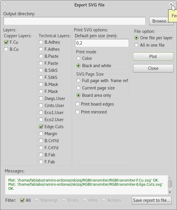
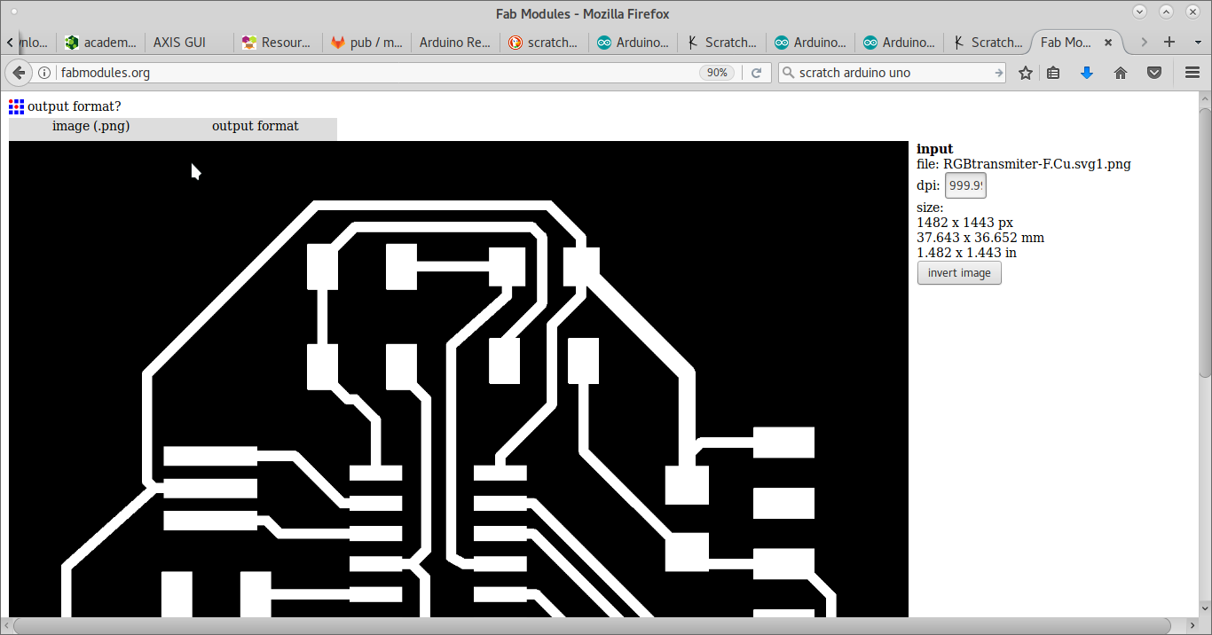
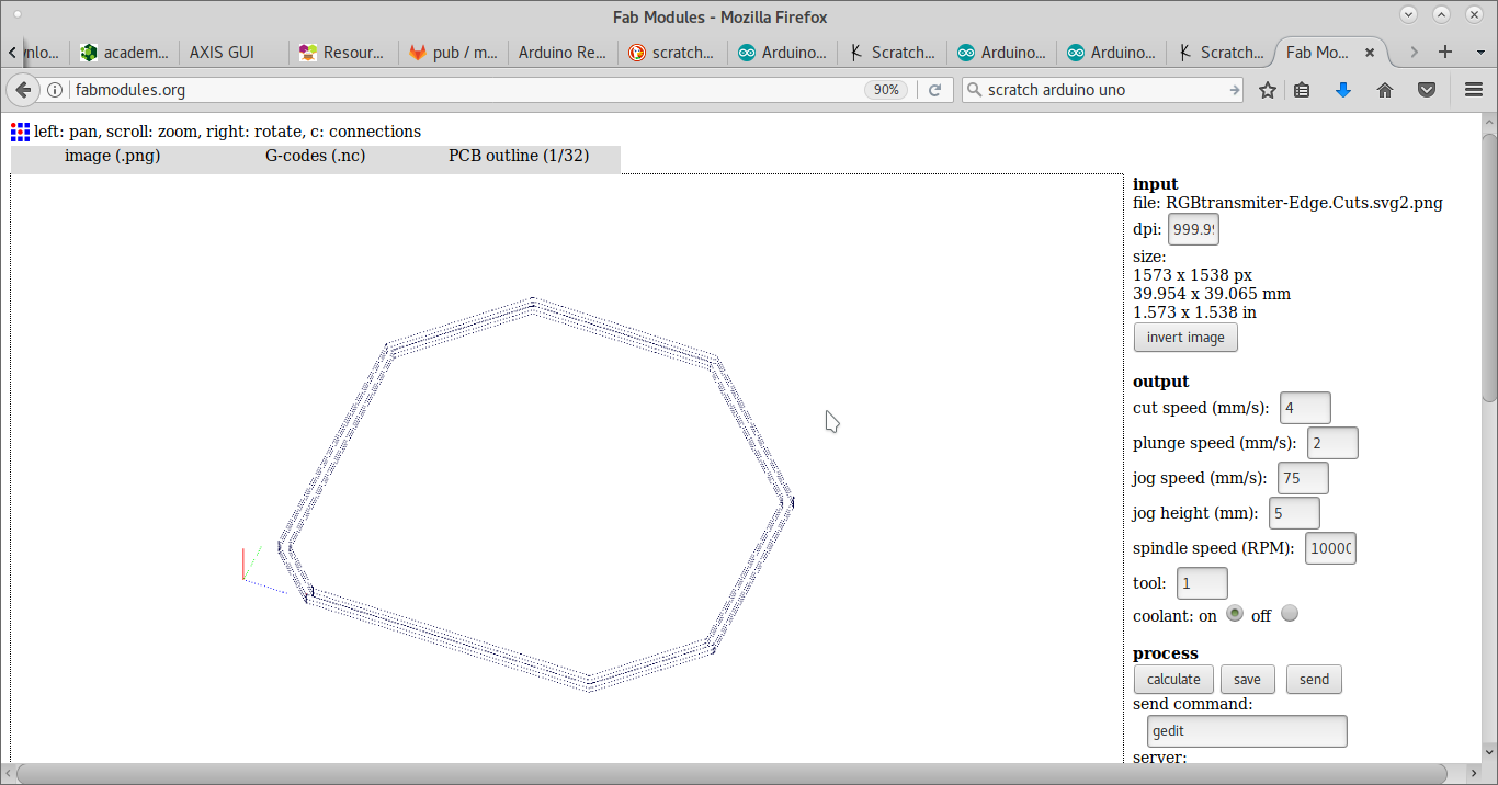
I decided to revert to Fabmodules and use PNG trace
and PNG cut files.

But then the PNG files have a size of 480.836 mm x 473.781 mm. They generate immense Gcode files on Fabmodules.
I reduced the size of the PNG files on Inkscape and generated the Gcode files on Fabmodules.
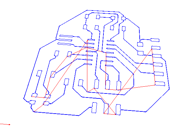
This is the trace file
And this is the cut file
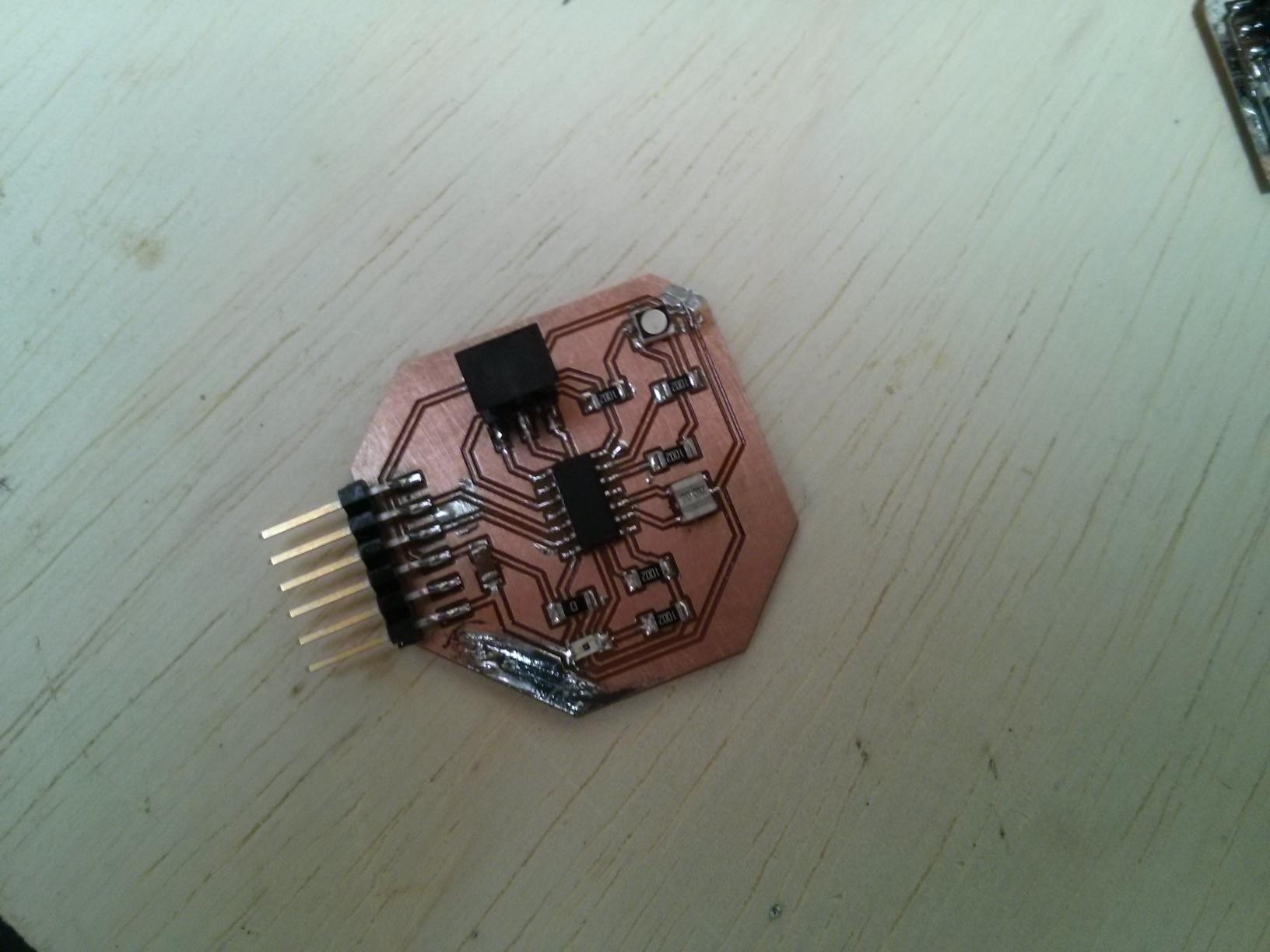
This is the photo of the finished board.
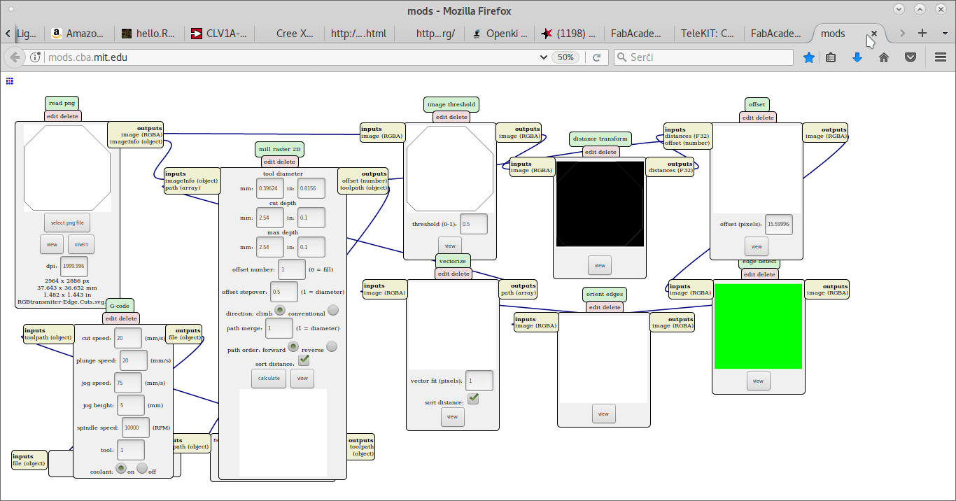
At Mods it we right-click on an empty area.
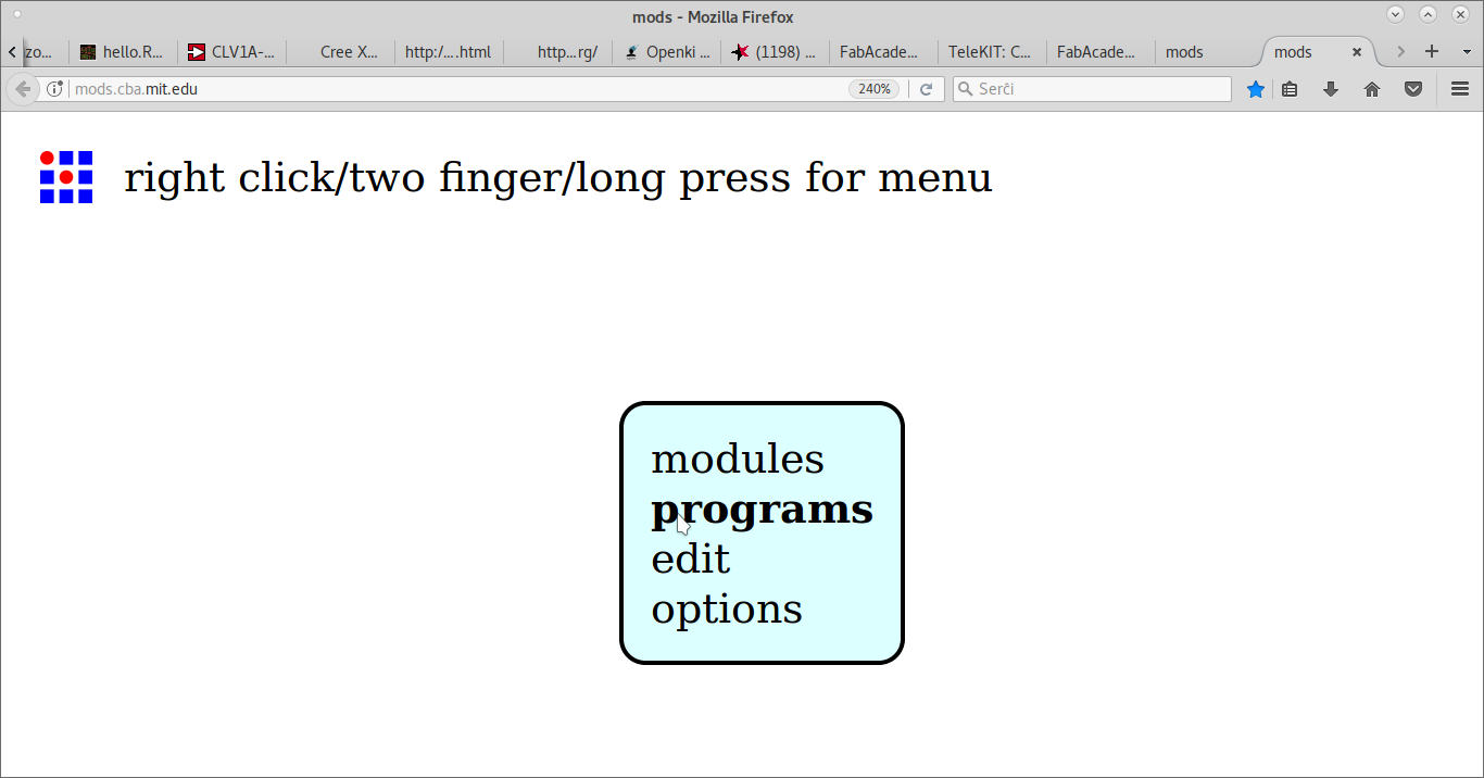
Upon selecting programs, we get to select to open server program.

On the machines' G-code section, we select mill 2D png.
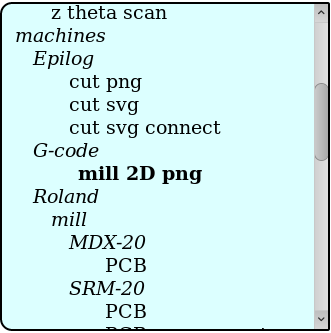
With that Javascript program, we can open the traces PNG file.
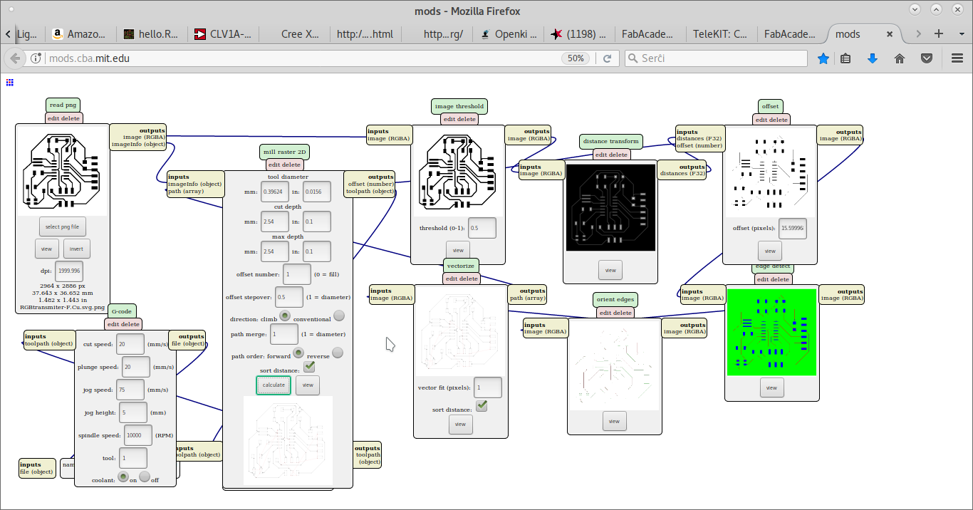
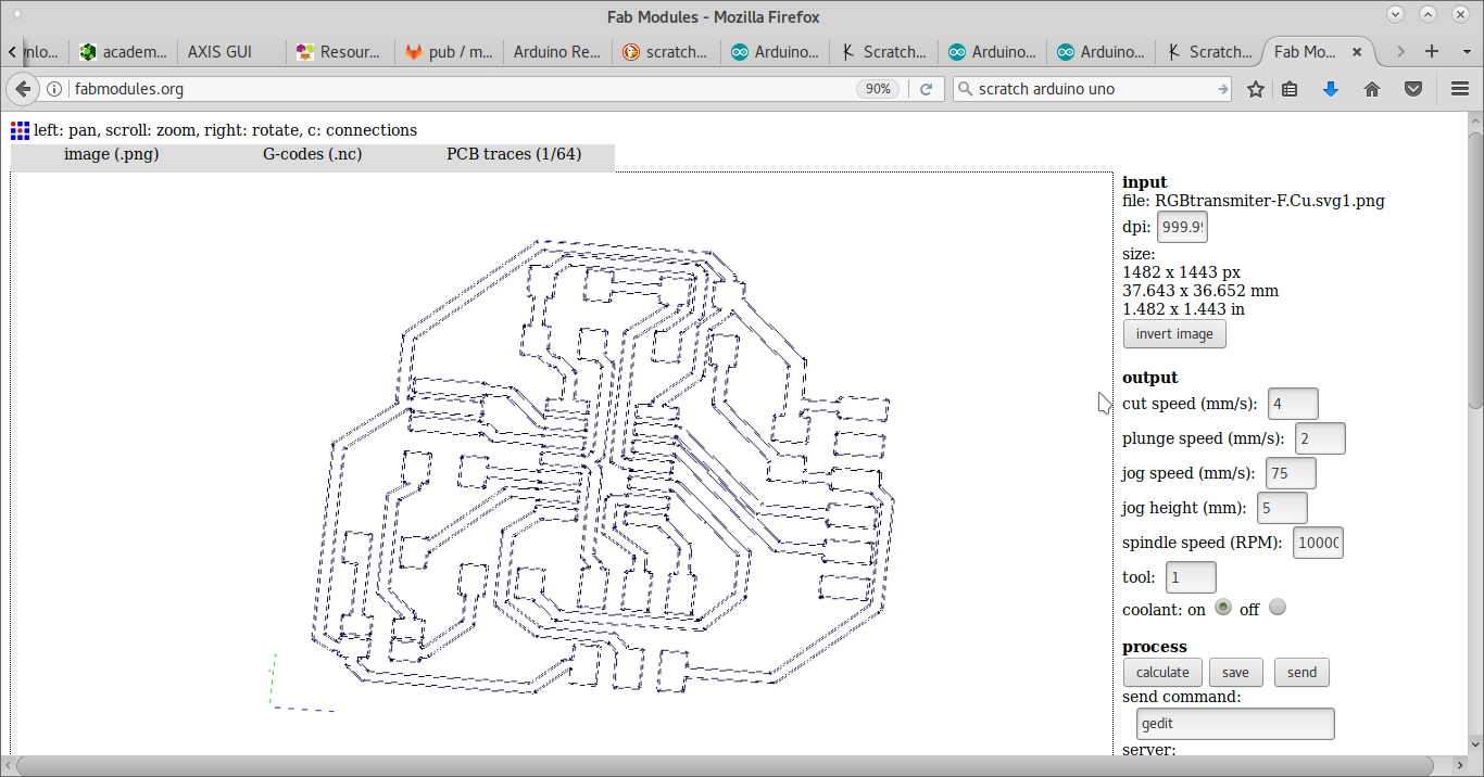
And obtain a G-code trace file.
The same way we can generate a G-code cut file.
For a circuit that has a phototransistor and an RGB LED, beside the PCB, the following parts are needed.
| Amt | Name | Part number | Description |
|---|---|---|---|
| 1 | Phototransistor | 1080-1380-1-ND | Phototransistor 940nm Top View 1206 visible |
| 5 | Resistor | 311-10.0KFRCT-ND | RES 10.0K OHM 1-4W 1% 1206 SMD |
| 1 | Capacitor | 445-1423-1-ND | CAP CER 1UF 50V X7R 10% 1206- |
| 1 | RGB LED | CLV1A-FKB-CK1N1G1BB7R4S3CT-ND | LED RGB DIFFUSED 4PLCC SMD |
| 1 | Resonator | XC1109CT-ND | CER RESONATOR 20.00MHZ SMD |
| 1 | Header 2x3 | 609-5161-1-ND | 6 Positions Header Connector 0.100" (2.54mm) Surface Mount |
| 1 | Header 1x6 | S1143E-36-ND | SMT RT Angle Male Header 0.1" (36pos) |
| 1 | MCU ATTiny44 | ATTINY44A-SSU-ND | IC MCU AVR 4K FLASH 20MHZ 14SOIC- |
I programmed the MCU to read the phototransistor and use the same value for the light intensity on the LED. My simple code in Arduino IDE contains something similar to this:
void setup() {int val=0}void loop() {val = analogRead(13); // read phototransistor input pinanalogWrite(12, val); // write LED output pindelay(10); // wait some milliseconds for next reading}The code is in the Light intensity sensor program and it is described at the Embeded programming lesson.
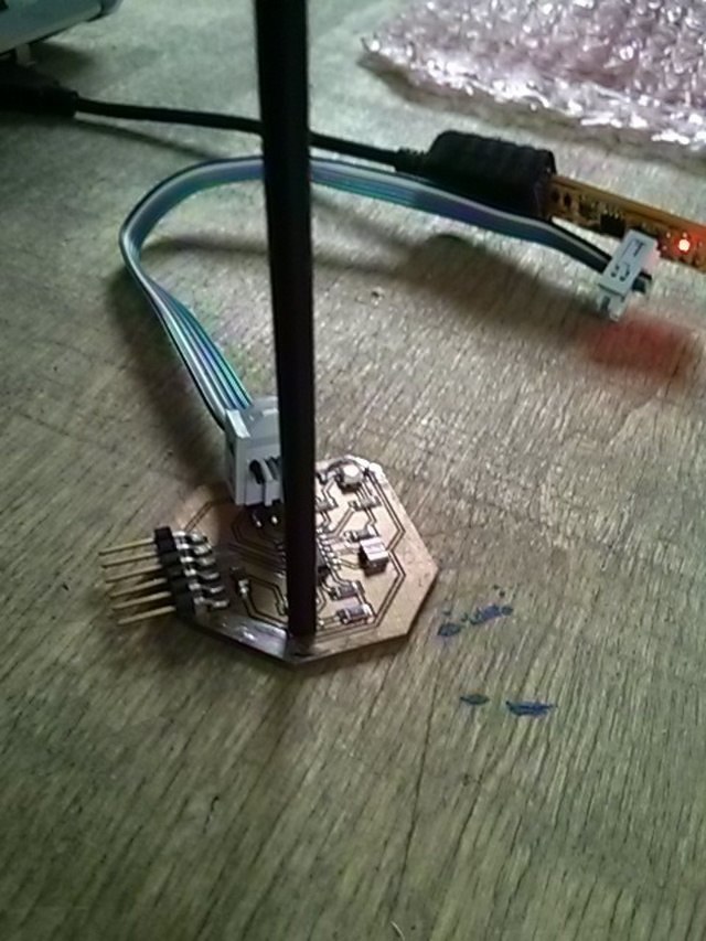
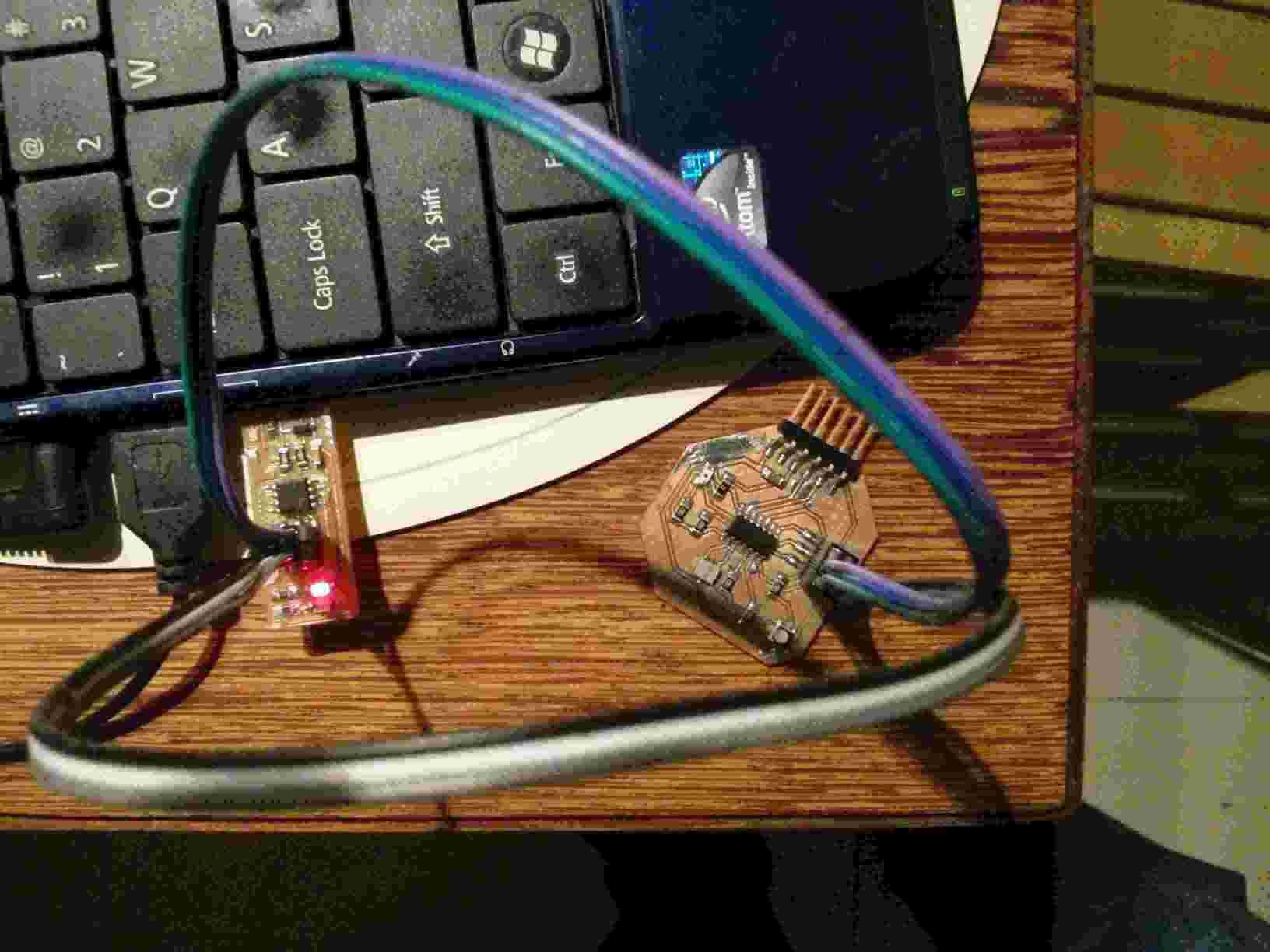
This is the programmed board.
I had doubts about my Hello World design because I had seen my oscillator had 2 contacts. But the Eagle Hello World tutorial said that it had 3 contacts. I did not understand where to place the other contact. I concluded that it would be connected to ground. So I looked in the local inventory if there were 3 contact oscillators. I found the 3 contact 20Mhz oscillator and the oscillator data sheet. This made me feel more confident of the choice of component.
I found synchronous detection fabulous for making very precise measurements. I thought what Neil showed in his synchonous detection example was applicable to my case. I needed to detect the difference in ambient light by having a separate phototransistor because I was not going to waste valuable RX time to contrast data detection with ambient light.