At first, the wax was not available for cutting a matrix. So this matrix was going to be made out of wood. Then the wax arrived. The wax matrix would serve to make a silicone rubber cast. The silicone rubber cast is used to cast the paraboloid parts that will reflect light rays from the transmitter LED and to the receiver PhotoDiode.
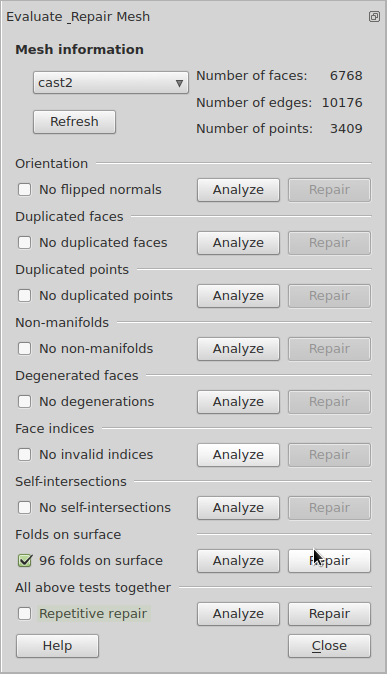
is exported to a paraboloid matrix STL. That file is fed into Fabmodules. It would not recognize my file. But in the Slic3r manual there is a section which describes how to use FreeCAD for repairing my STL file:
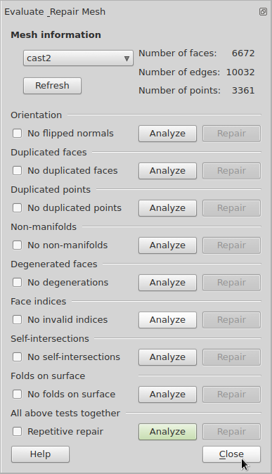
Make sure the repair did not damage the mesh. Then you can File -> Export the file to STL format again.
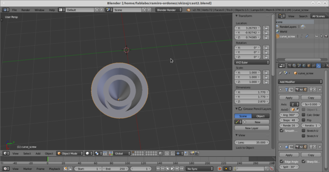
The next step I did was to feed it to FabModules and choose the STL mesh as Input File.
Since the image was adjusted in Blender as 1 pixel per millimeter, I changed the value of DPI in Fabmodules to 25. But my instructor recommended to keep it on the default values. So I used 1000 DPI.
Then choose Gcodes (nc) as output file which produces Gcode for the paraboloid molding cast.
Nevertheless, the nc file was not recognized by LinuxCNC.
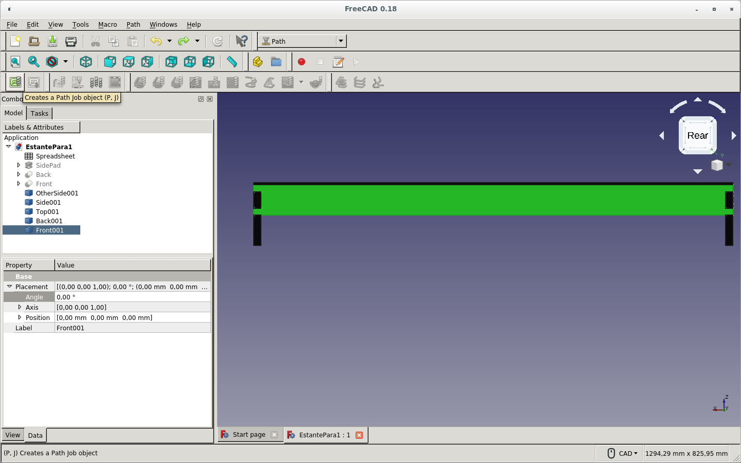
Choose the Path Workbench.
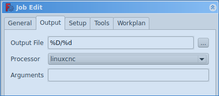
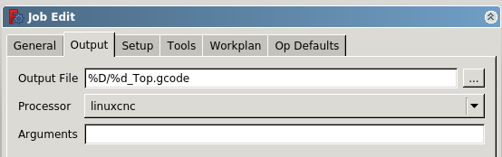
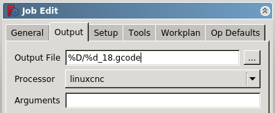
Then create a New Path Job by choosing the the apropriate button. On the window that is opened, define the output file name and location. Also choose the postprocessor for the apropriate CNC router.
Select the Tools tab.
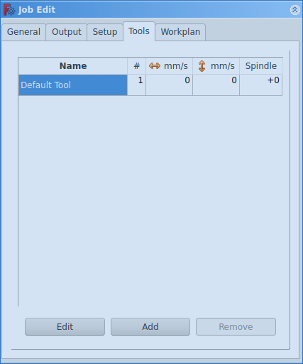
Edit the default tool.
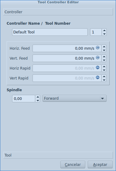
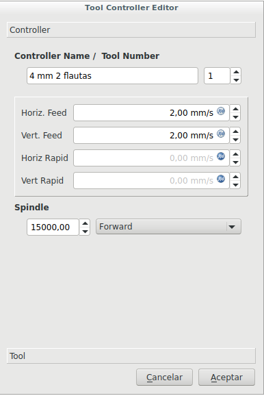
Specify the Controller parameters for your machine.
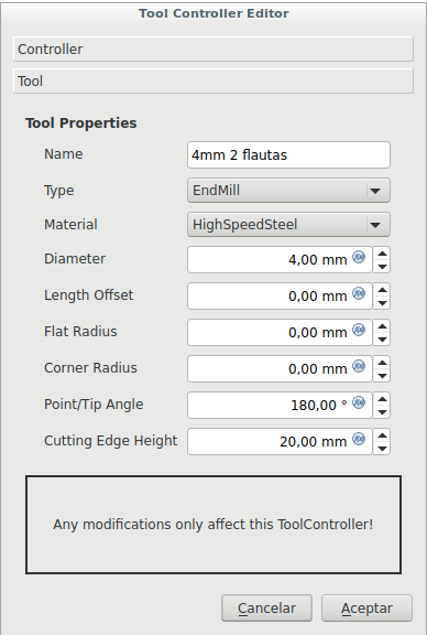
And the Tool parameters for your mill.
Unfortunately I was not able to use the experimental 3D pocket tool in order to create the apropriate paths.
The successful machining process could be completed in the machining section of the molding and casting lesson. It was machined on MDF wood. The problem with the former design process was probably that the mesh was not closed or that the tool was tool thick for the pockets or another mistake due to lack of experience and knowledge about the workings of the design process and Gcode generation.
As a group assignment we decided to design and build a loft in order to increment the fablab's usable space since most of it is being used by the laser cutter and the CNC router.
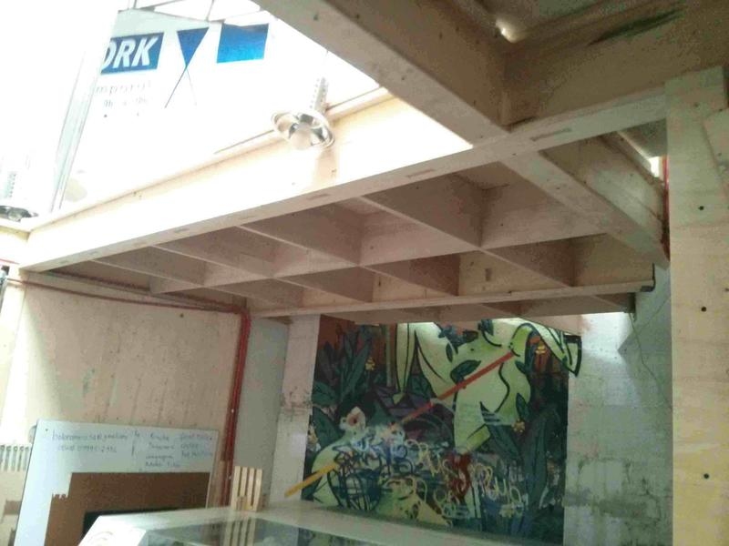
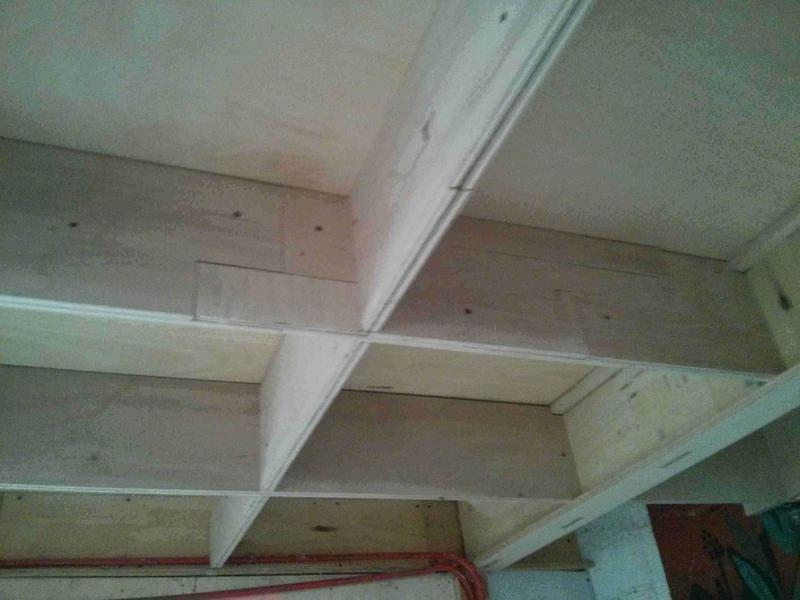
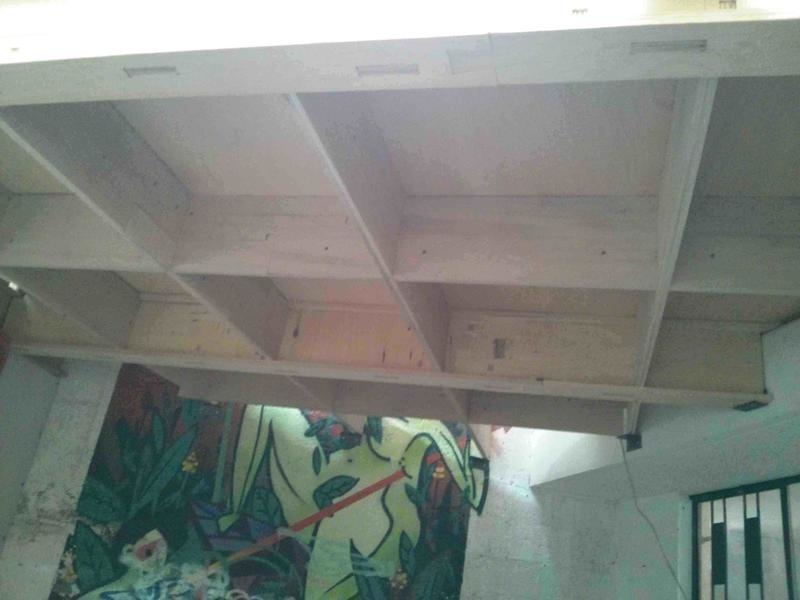
The beams are constructed from plywood in I form in order to give them greater resistence to torsion on the horizontal axis if the internal forces turn parts of the loft. The beams intersect with the nerves (which are thinner beams) and give the structure much better cohesion. The floor of the loft is plywood also. Press-fit is used on the beam, nerve and board pieces and at their interconnections.
A bridge was also constructed in order to link the stair access of a storage area to make it serve the loft area too.
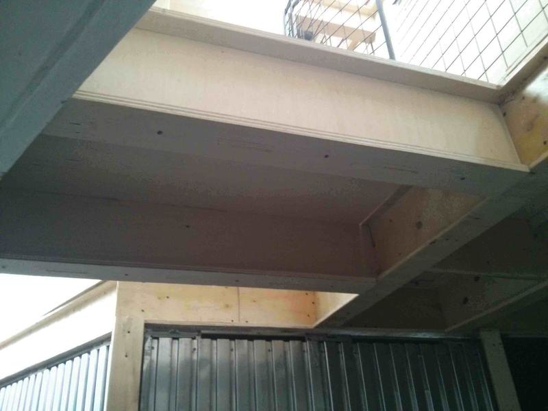
The loft and the bridge structures did not fit correctly to the area of assembly. It is not the same to make furniture (which does not have limiting entities) as to make a floor which might not fit in the existing area. The structures had to be cut in order to insert them where they were fit.
This is the software I am using.
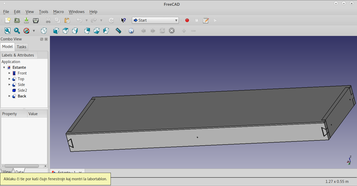
A simple shelf such as this:
could be thought of being a simple task. Nevertheless, learning parametric design and press-fit makes things tough for a newbie. It proves better in the long run because of the modularity of parametric design.
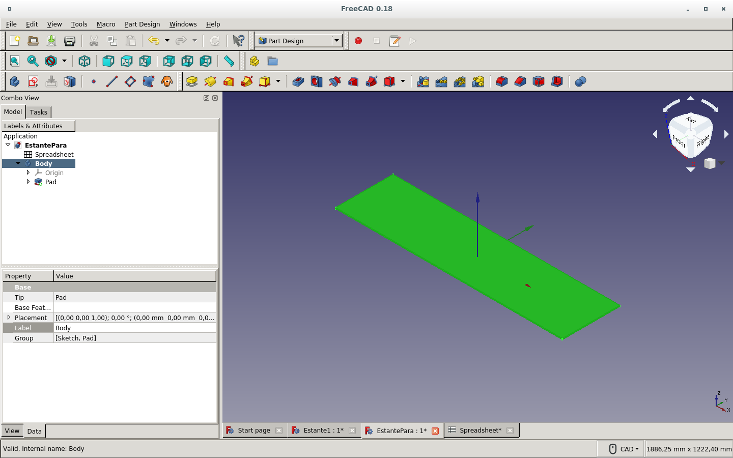
I used the dimensions of the horizontal plane of the space where the shelf would be placed. On the Part design workbench (select it on the drop-down menu that shows Start):
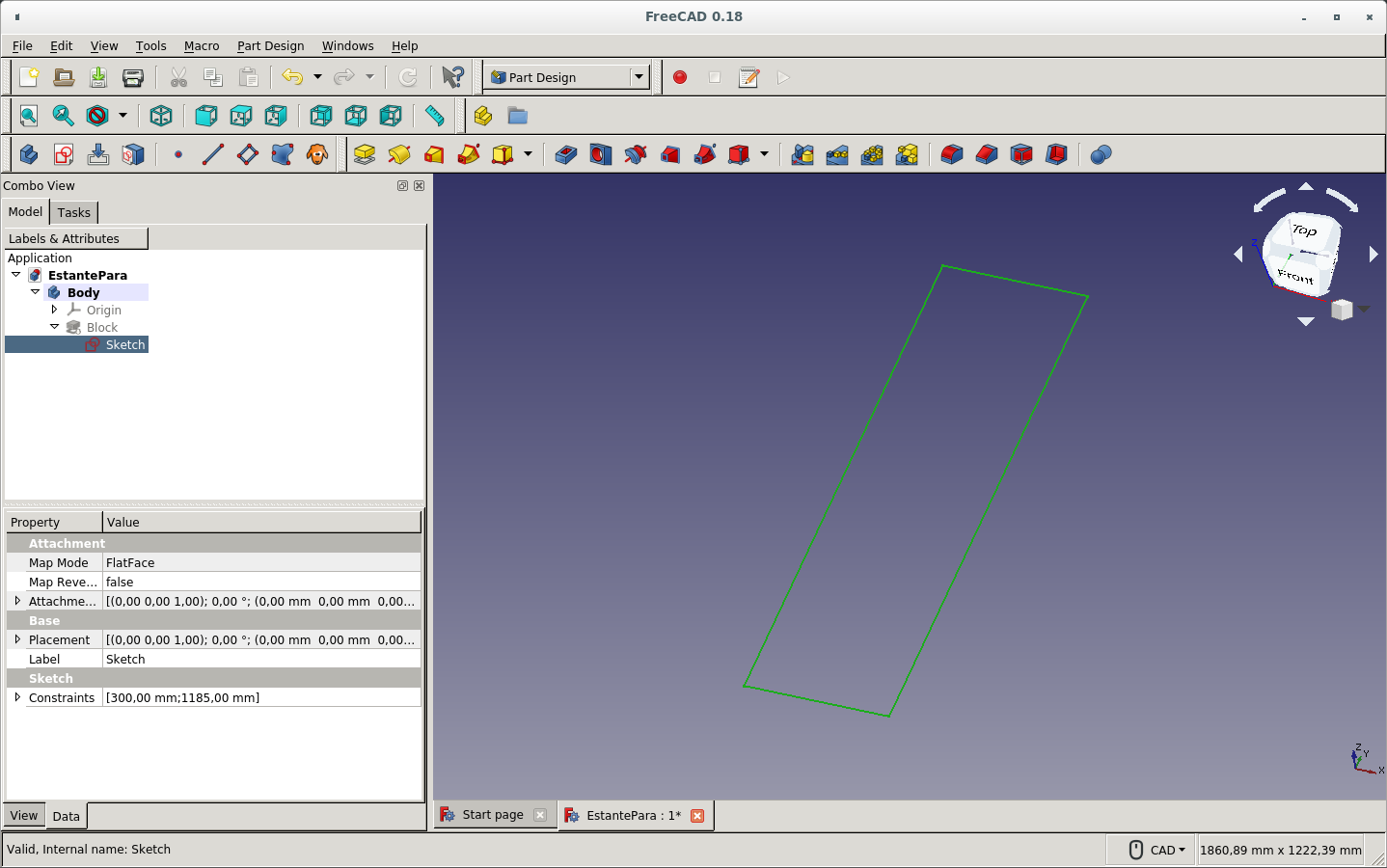
It produced this sketch viewed from an angle.
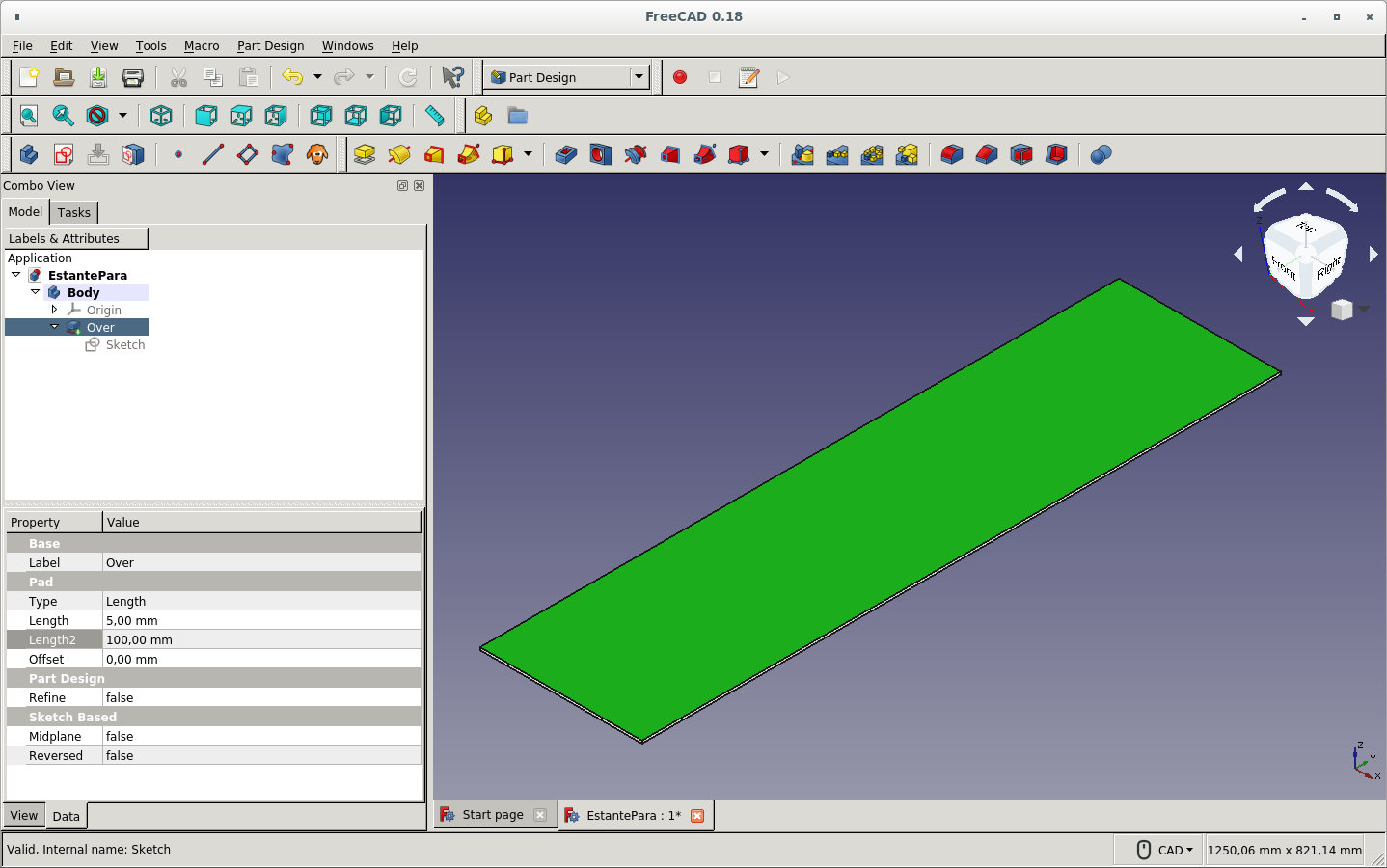
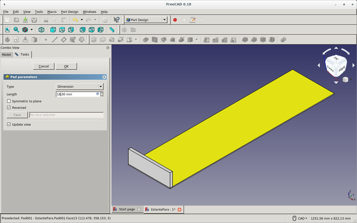
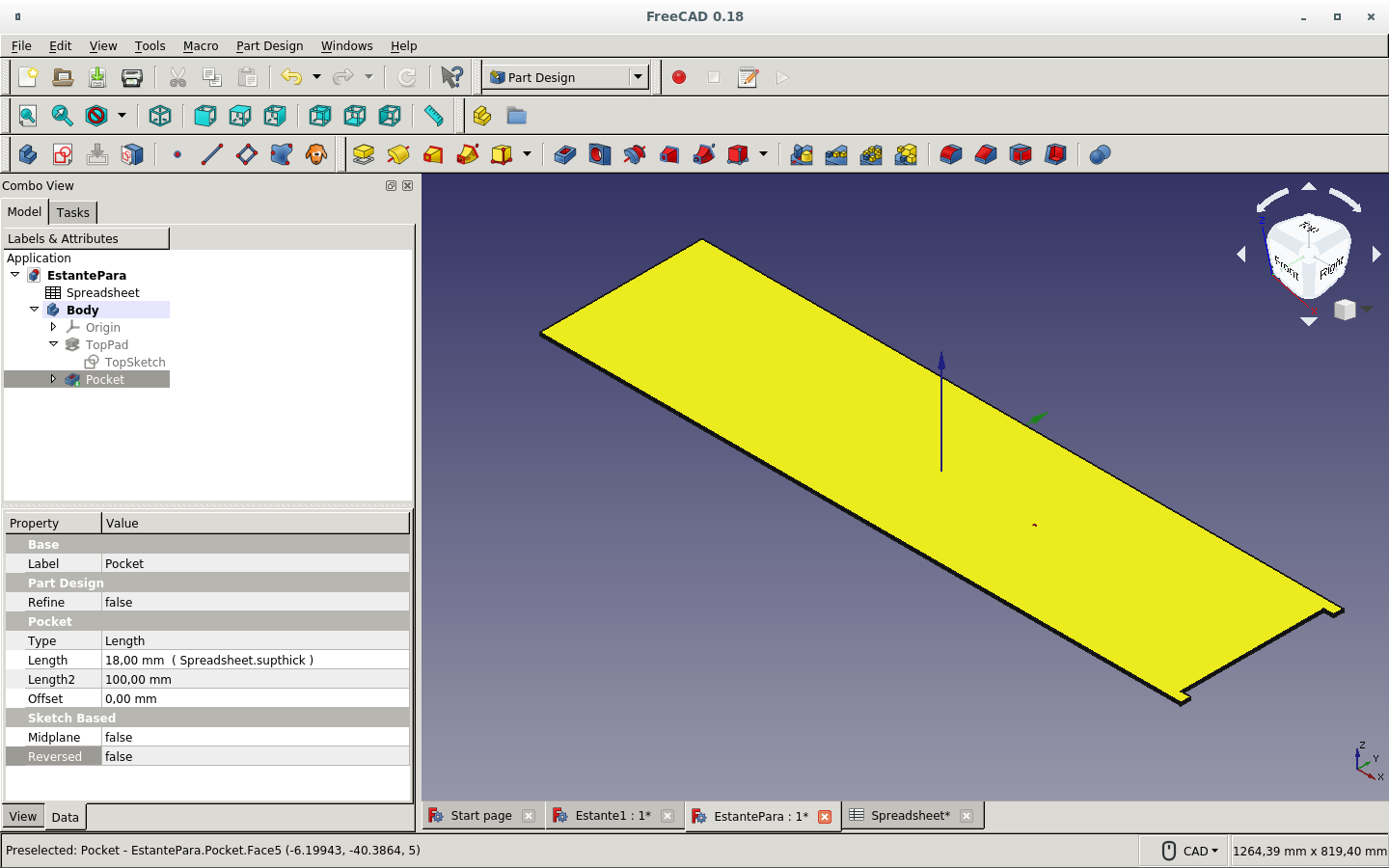
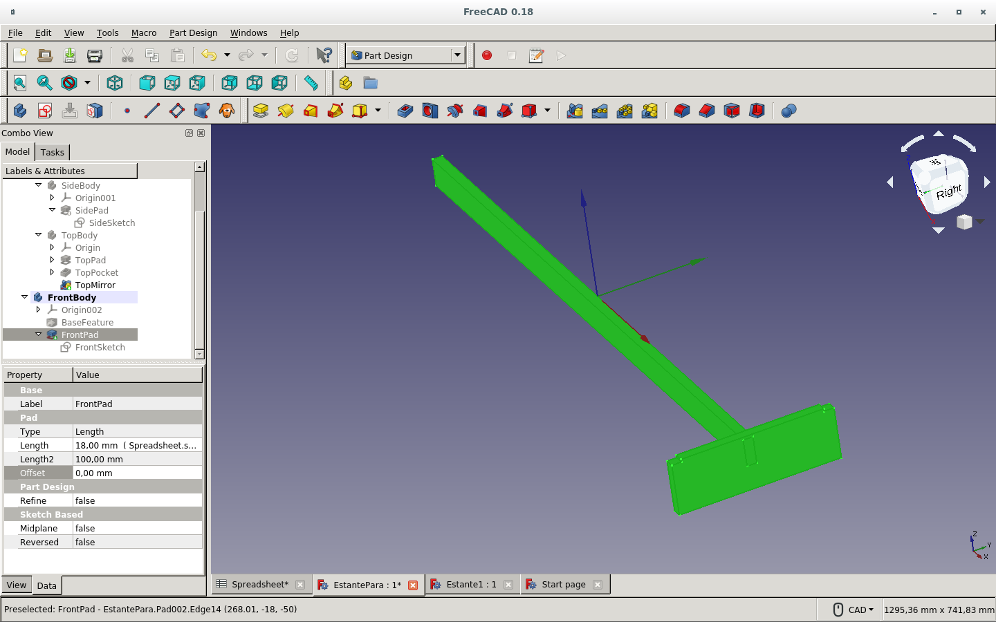
Then I made a solid of the desired thickness with the Pad icon. It made the horizontal shelf (top) board.
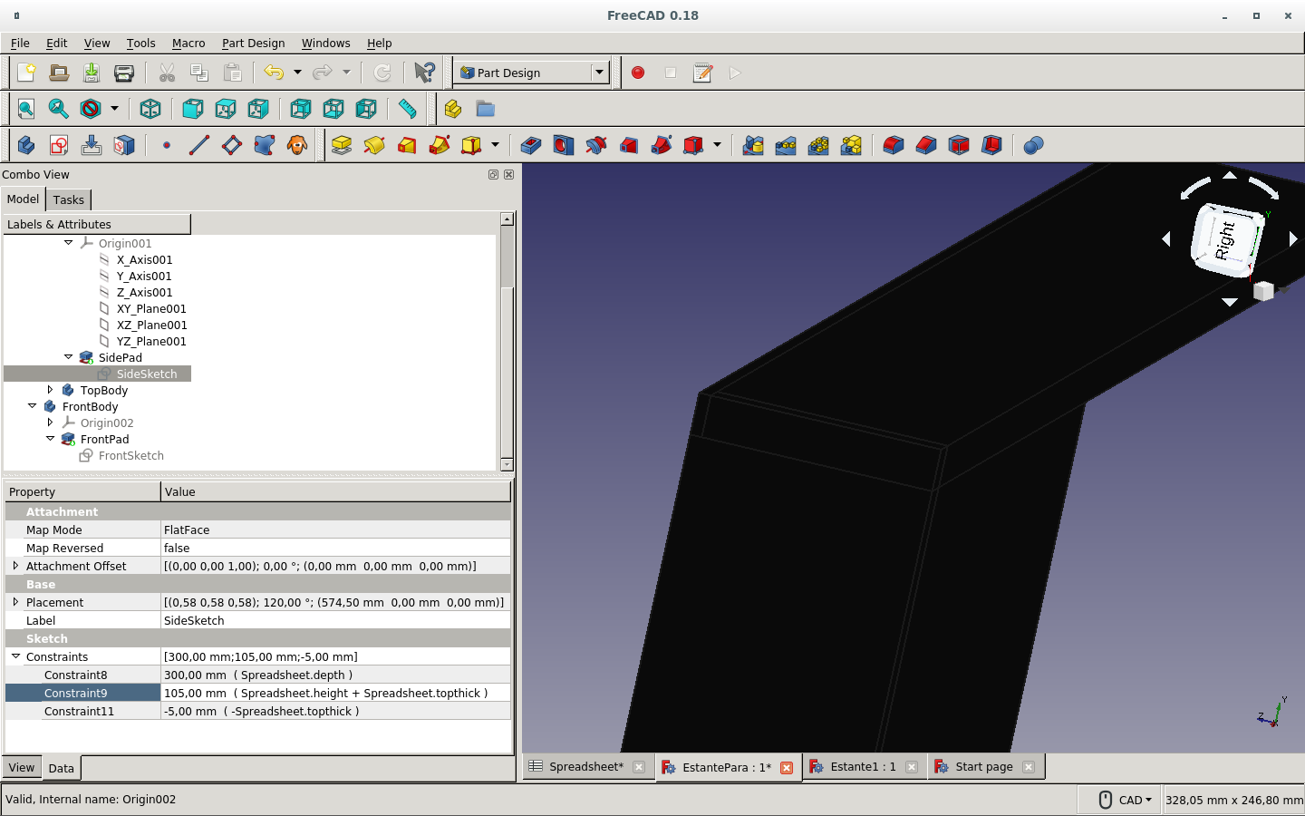
On the XZ (vertical) plane of the side of the solid I produced before I made a new sketch.
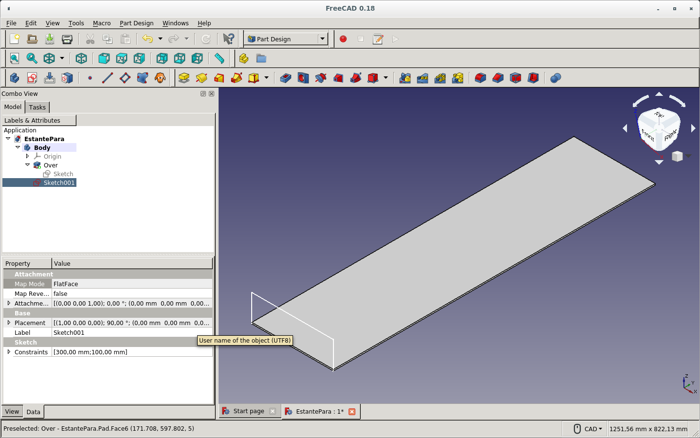
And then used the Pad icon for giving it a thickness length in order to make a solid out of it. It was to be one of the side panels.
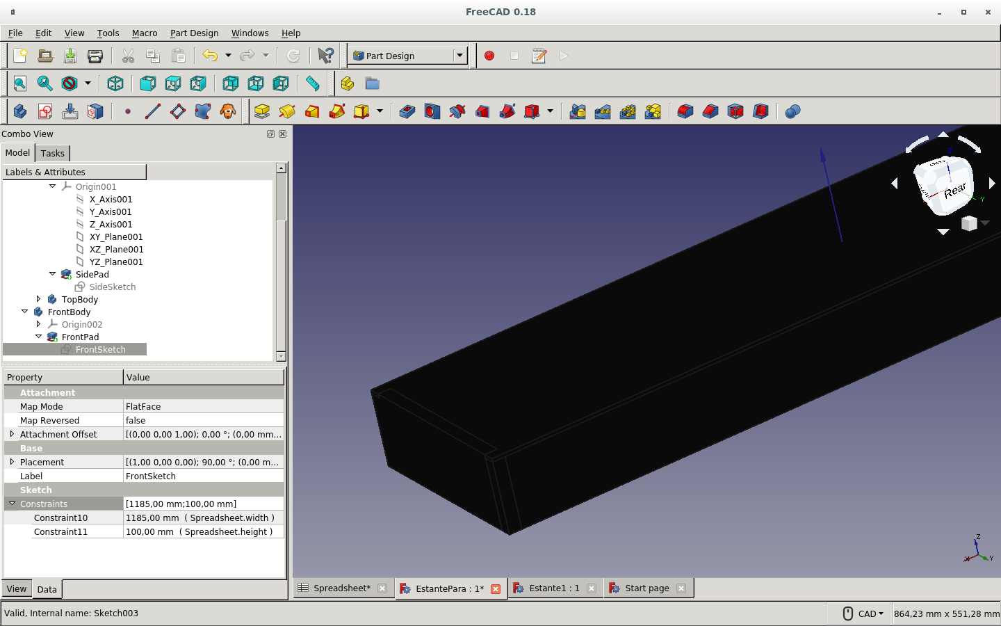
Then I drew the front-board's sketch.
I started a new file by just drawing a cube for the top board. I used the Cube Solid icon on the Path workbench (not the Part Design workbench).
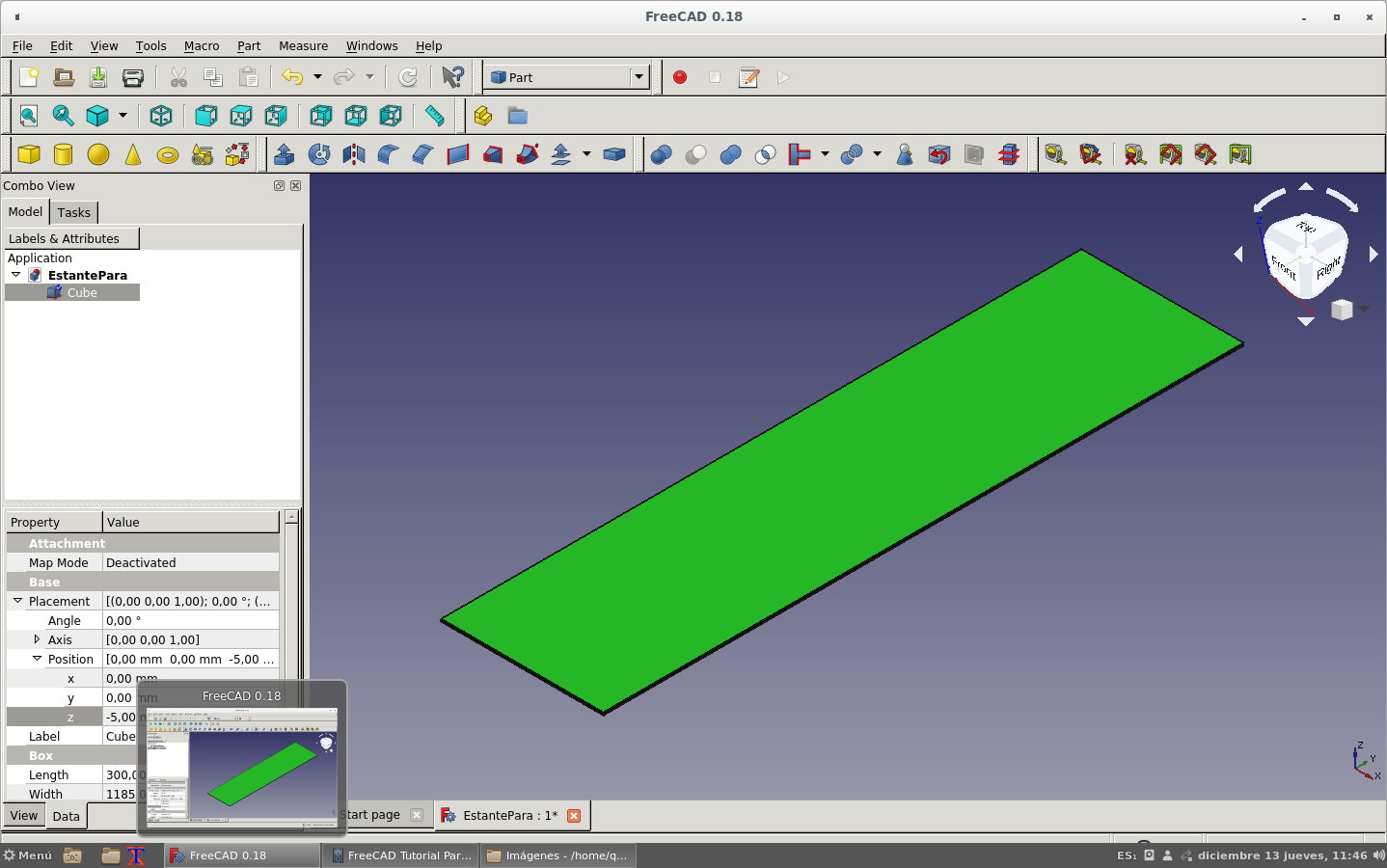
Changed the name of the created solid.
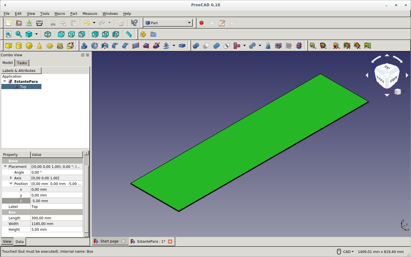
Then drew the side cube with the appropriate dimensions.
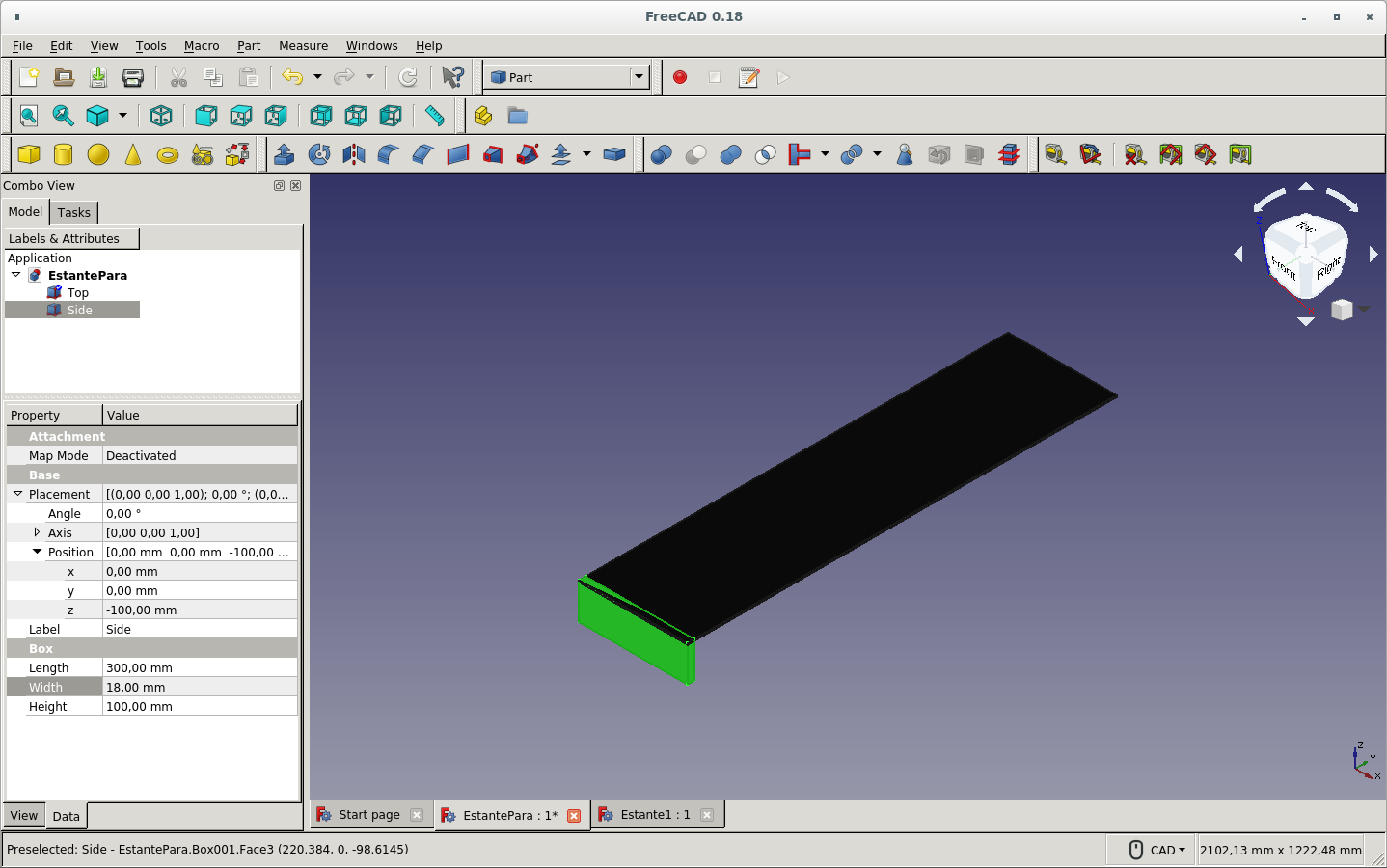
But later I returned to drawing the sketches and padding for making the solids.
When I finished the shelf parts and the press-fit cuts on each part, I rotated the parts in order for them to be on the same plane for tracing the mill paths on Gcode.
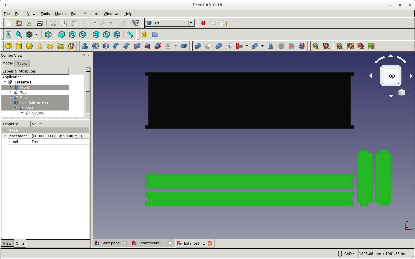
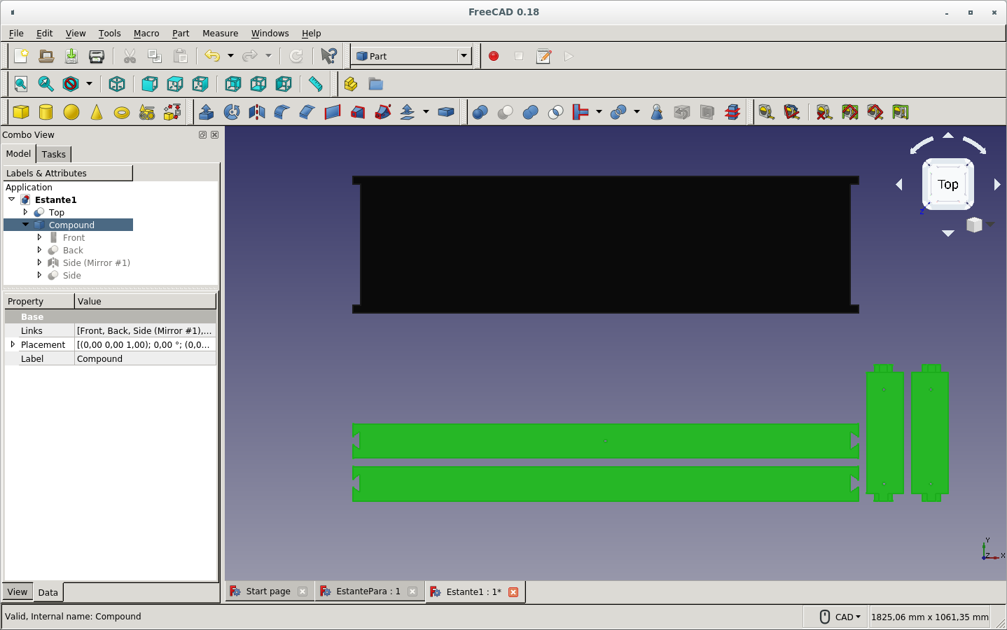
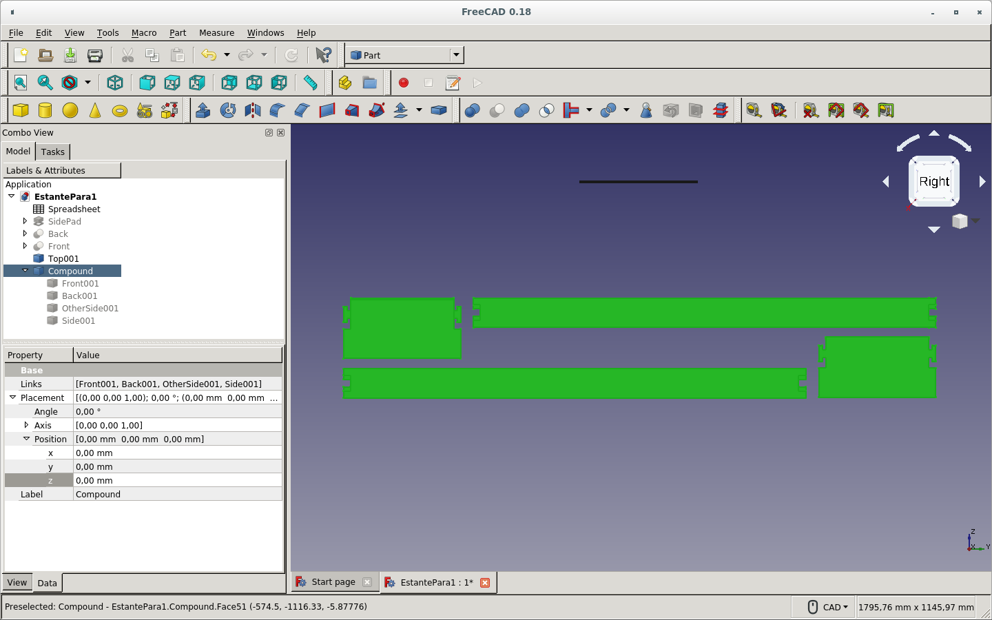
As version 0.17 of FreeCAD required to make one piece for milling on one board, I combined all the pieces to be cut on the 18mm thick board on one Compound. This tool is found on the Part workbench. (This hack is not necesary on version 0.18.)
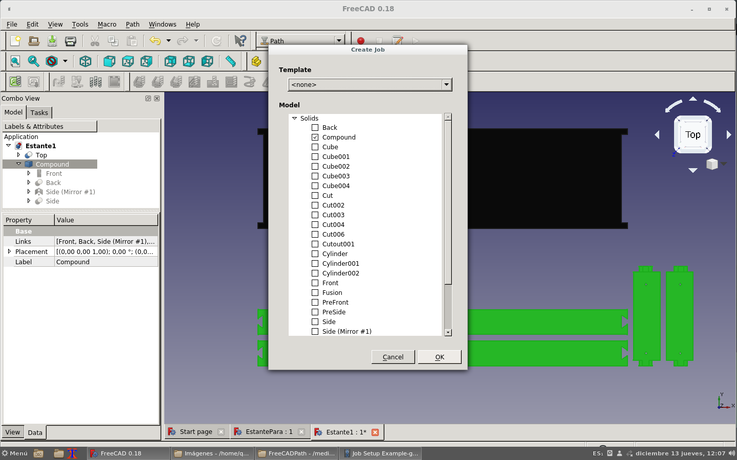
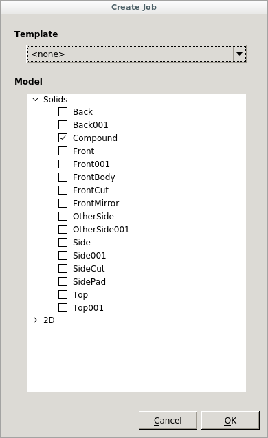
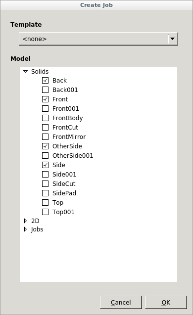
On the Path workbench I clicked on the New path icon. It would ask which pieces would belong to this path (as of version 0.18).
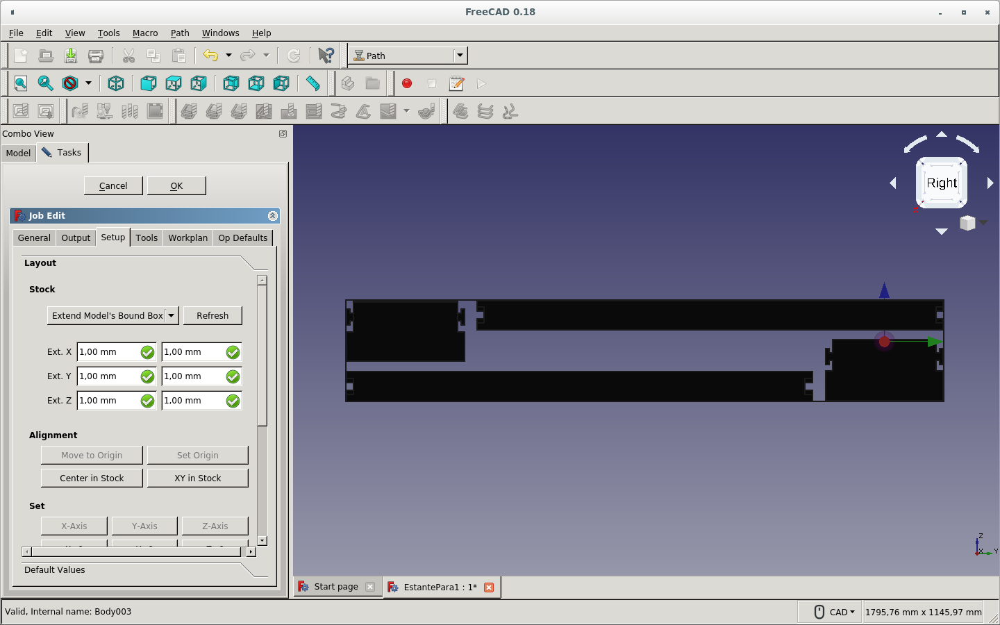
The Extended model's bound box creates a stock covering the area of the pieces plus some pre-difined extra. I removed the extra 1mm from the height (Z)and kept the rest.
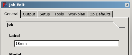
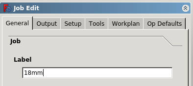
Renamed the name of the job.
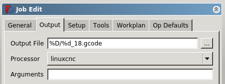
Defined the name of the output file as located on the original FreeCAD file directory and with the same name of the file plus 18 for identification of the board for that Gcode file. Finally added the extension as .gcode.
On the Tools tab, I created a new tool with the specifications of my endmill.
I used that tool and defined the specifications of the router on the controller setup.
I used the Contour icon for tracing the edges of the pieces.
I specified the particular specifications of this operation (default).
The same process for renaming the new job I created for the 5mm board for the shelf itself.
So the Contour path was the only necesary operation on the 5mm shelf board.
I made some tests with the 3D pocket tool icon for the press-fit cut on the side boards. But it would not mill parallel on both axes to the diagonal plane, just as can be observed on the photo. It would do a 2.5D operation as detailed on the introduction of this tutorial.
I created a new file with sketches and pads as before.
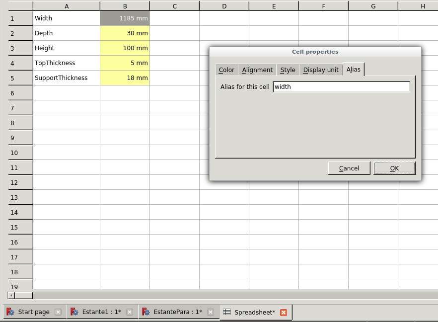
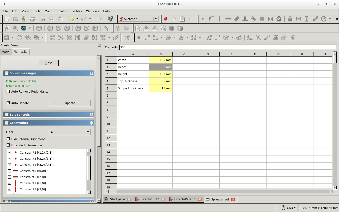
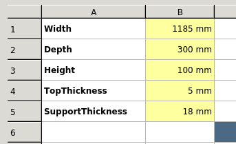
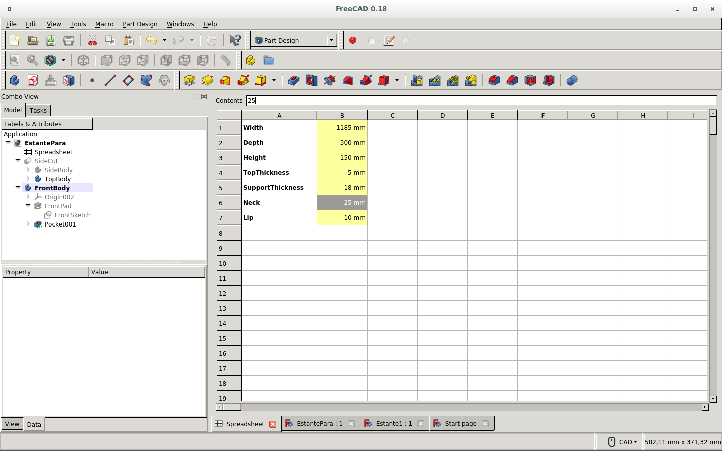
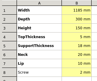
But now I defined the dimensions on the Spreadsheet workbench by creating a new spreadshet. I defined the properties of the cells that contained the parameters. I right clicked on each one and filled the Display unit and the Alias tabs.
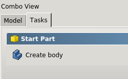
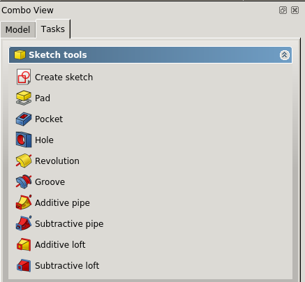
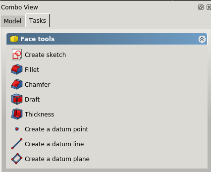
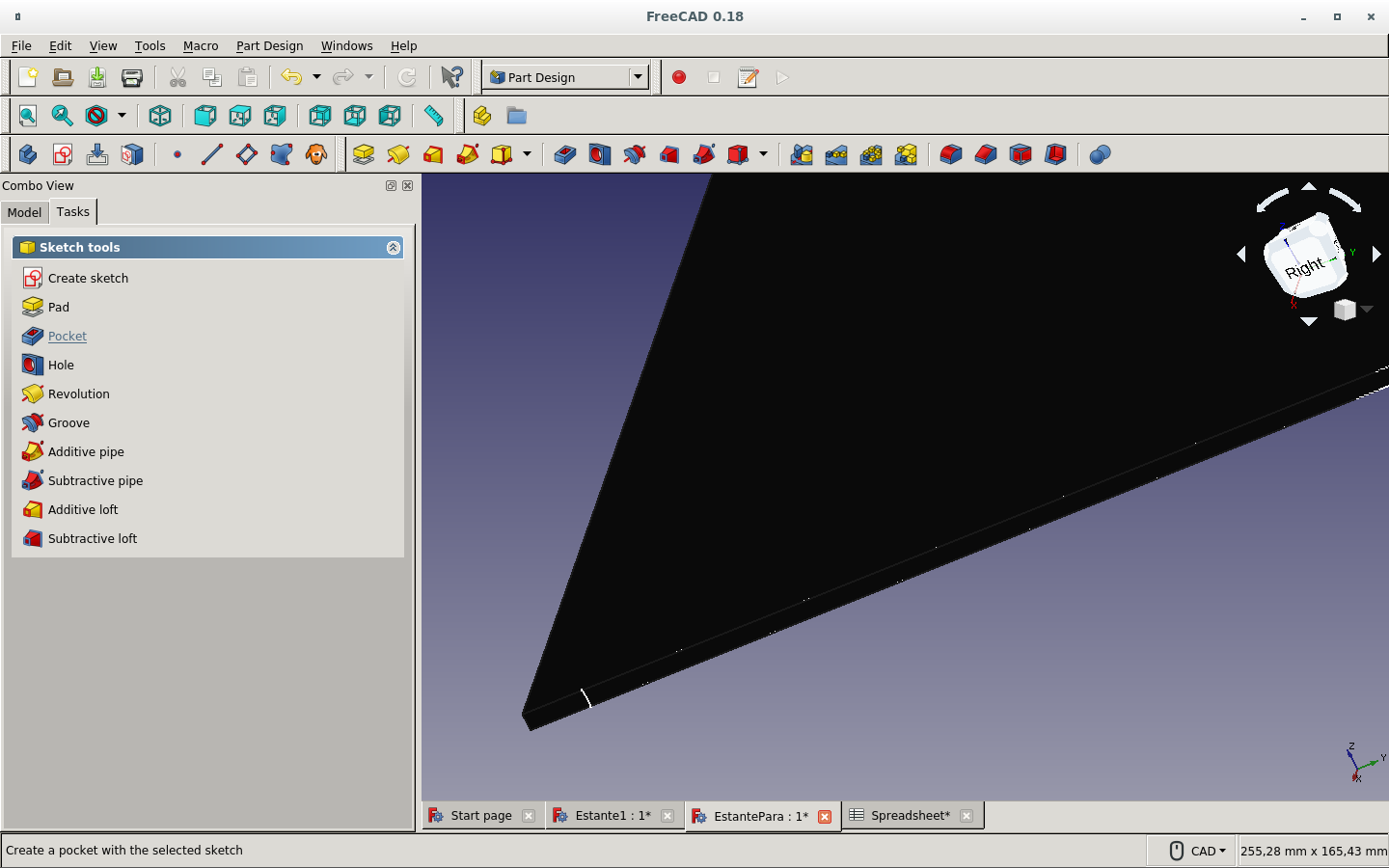
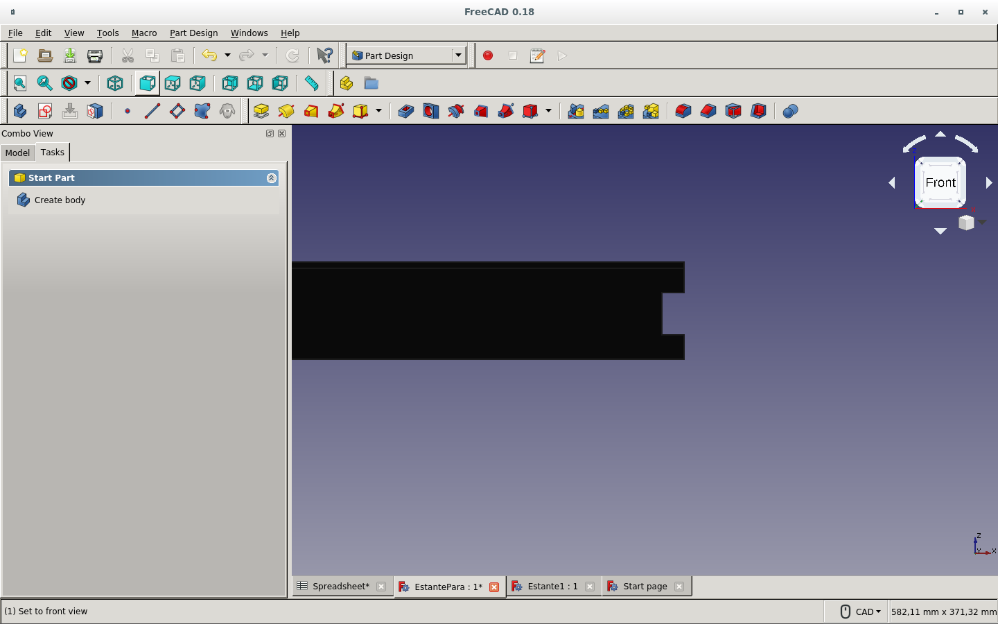
On the Part Design workbench, the Tasks tab offered to Create body. So I clicked on it.
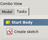
Then that same tab offered to create a sketch. I clicked there.
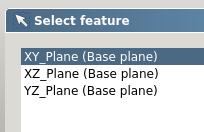
It asked which plane. I chose the XY plane.
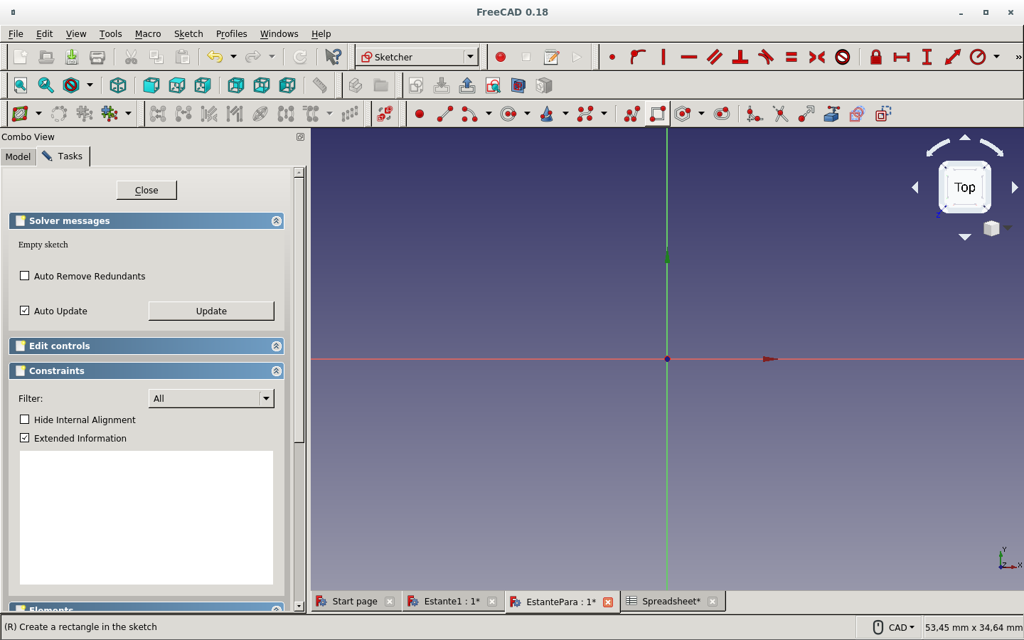
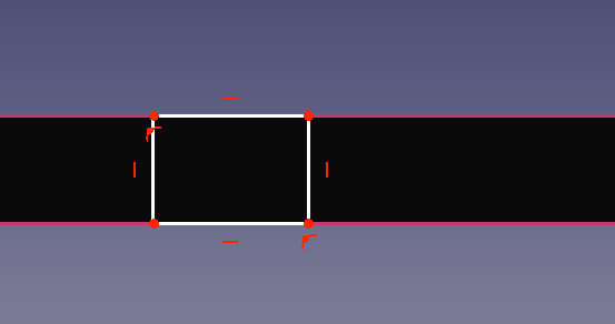
It expected some sketch.
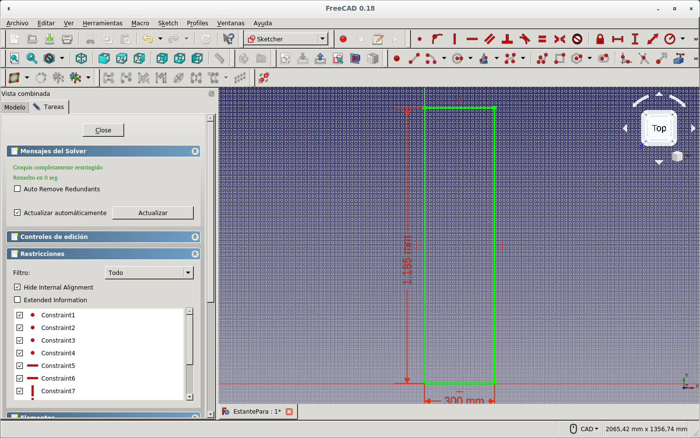
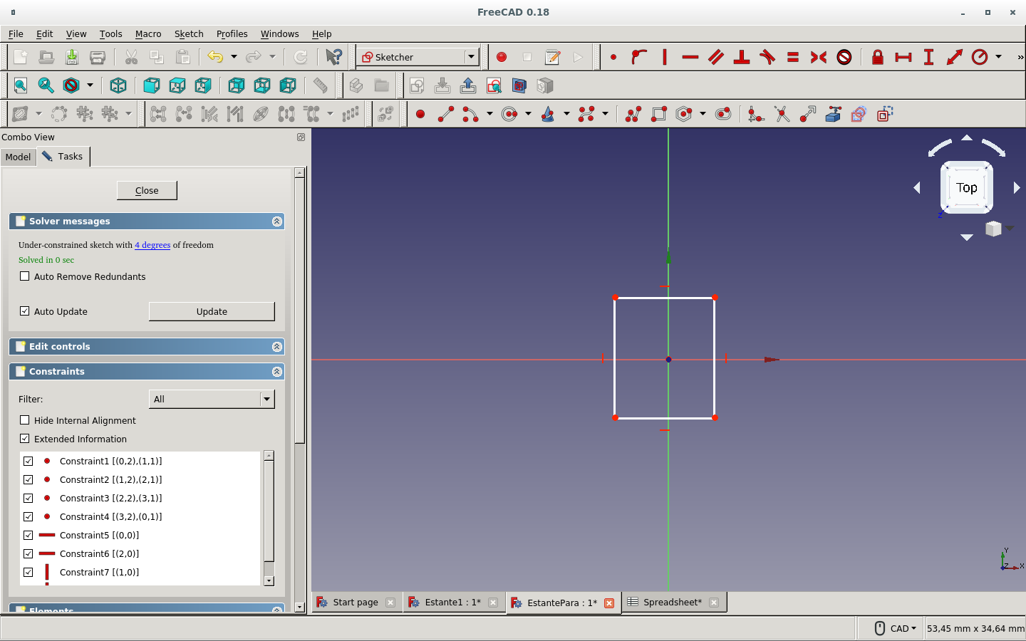
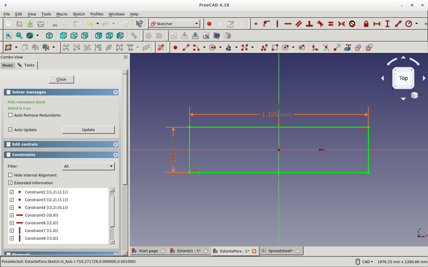
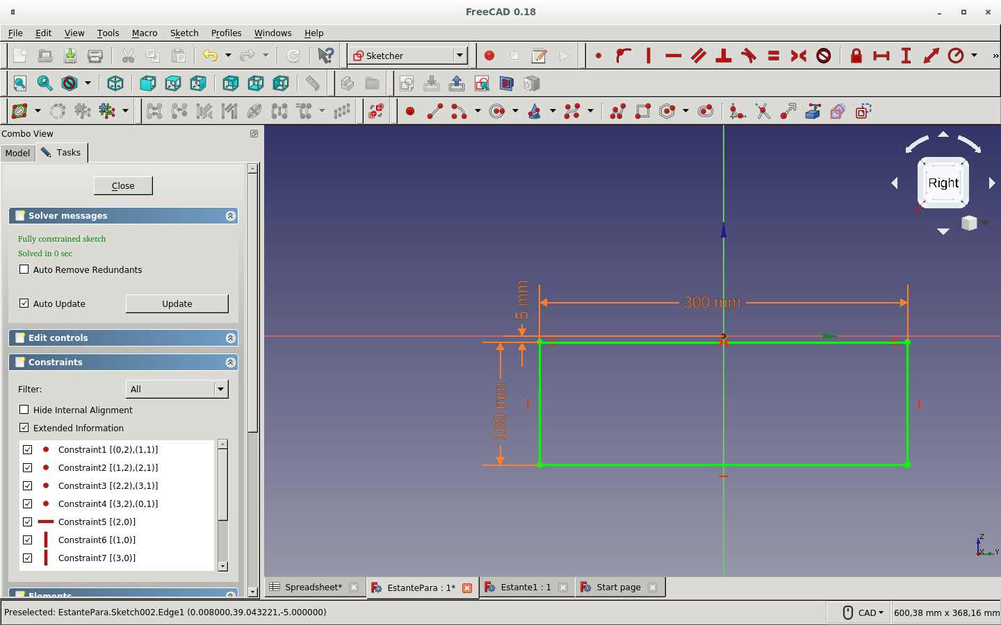
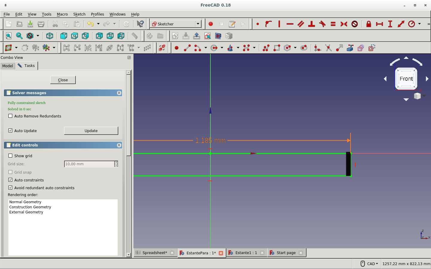
I drew a rectangle.
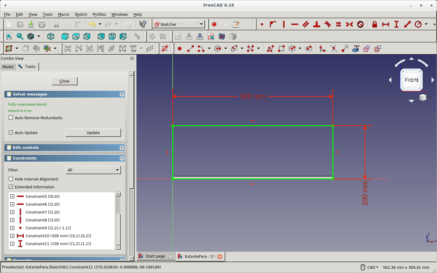
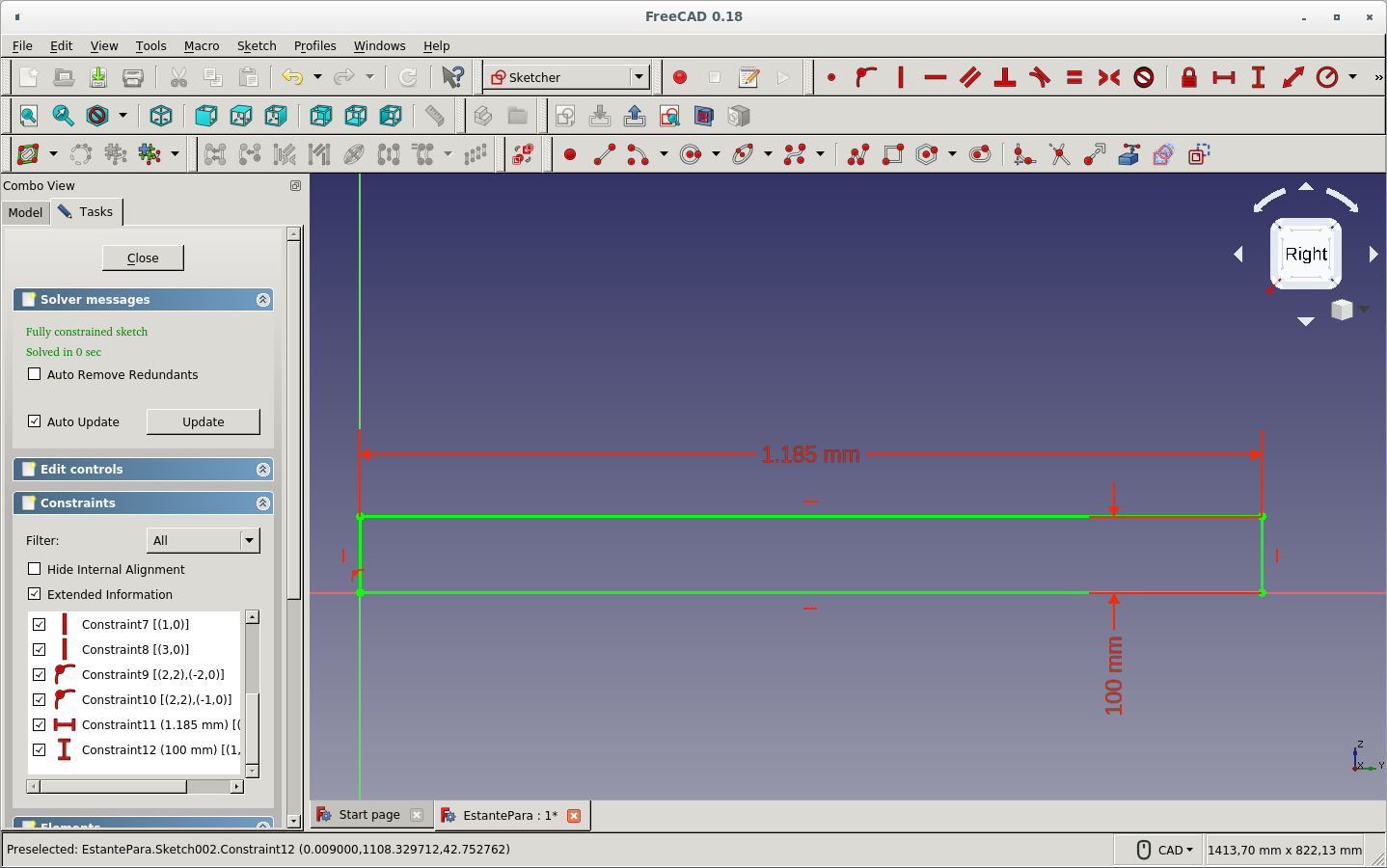
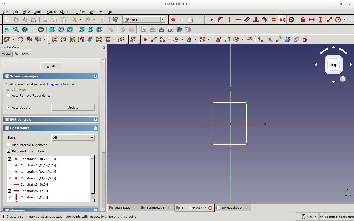
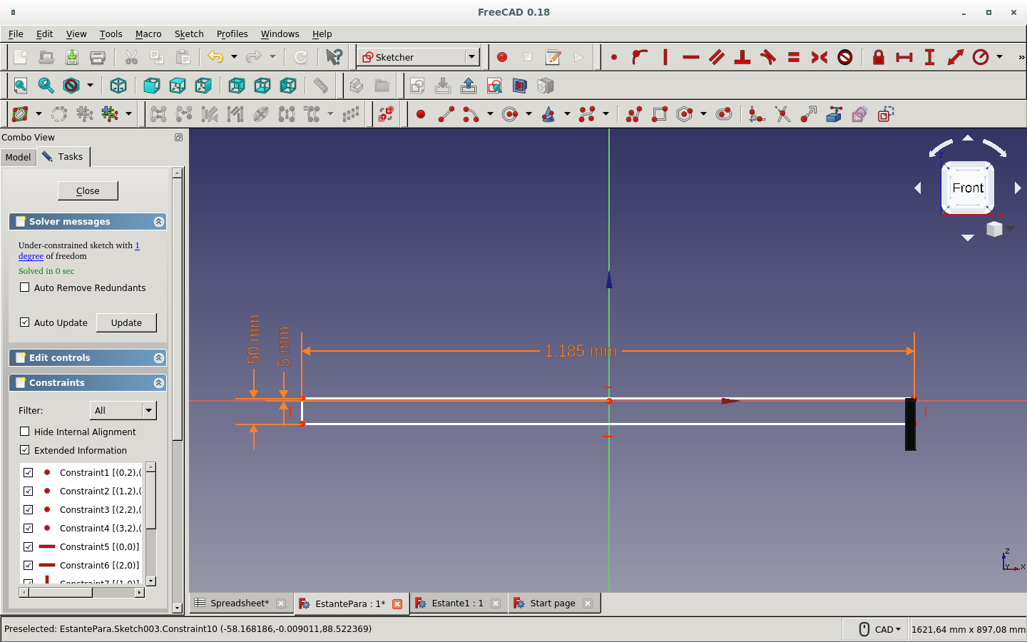
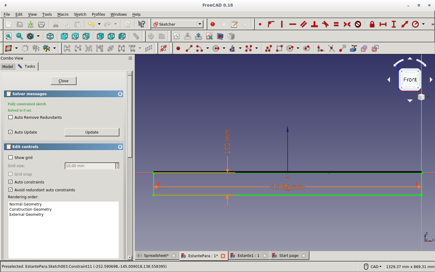
And used the Symmetry constraint of two of its opposite to the origin point in order to fully constrain the sketch.
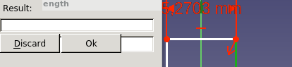
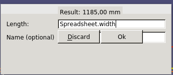
I clicked on the measurement icons: Fix horizontal (vertical) distance. An Insert length window appeared.
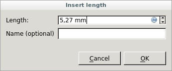
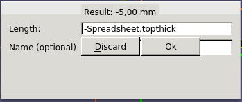
I clicked on the Fx icon.
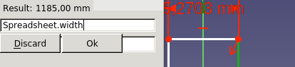
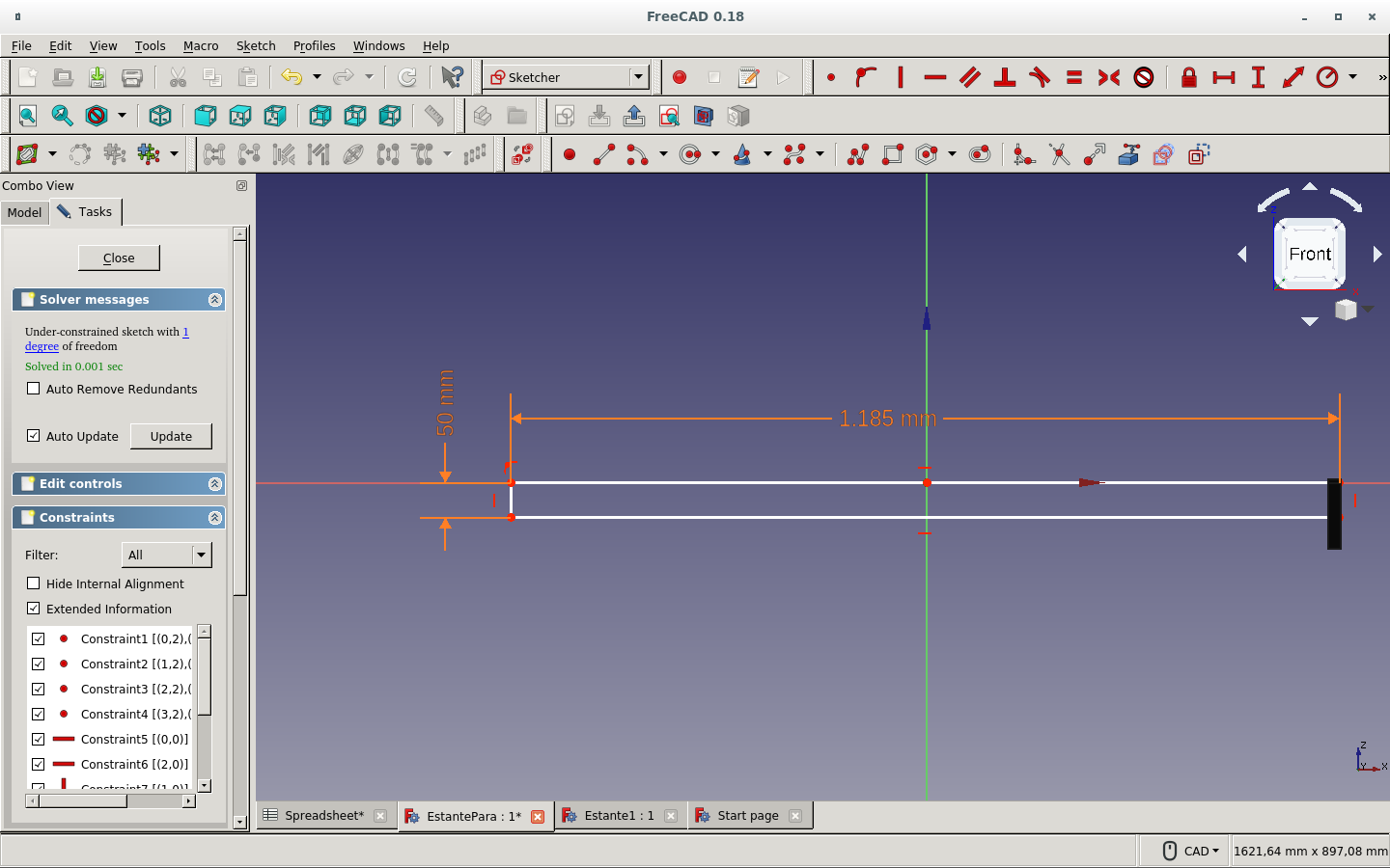
And typed the appropriate parameters: the spreadsheet object name and the alias for that distance parameter. This was the shelf space width.
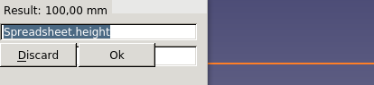
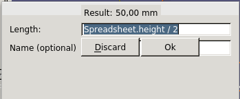
This was the height.
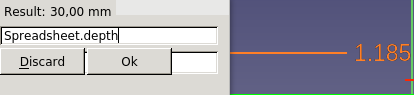
This was the depth.
Changed some of the parameters on the spreadsheet.
Created an new body and its sketch
Drew the sketch for front piece.
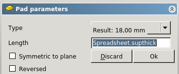
Made its pad for giving it thickness (as described above).
Defined the parameter alias.
Made the sketch to a solid with the Pad icon.
With the side face of the solid I just created currently selected, I create a sketch.
And select the edges of the face to use for my sketch.

Then I draw a rectangle.

And try to click on the edges to constrain it to the top board (the shelf board itself). This will make it have a dent on each side for the lateral or side boards to lock in with their thickness as the dimension of the dent.
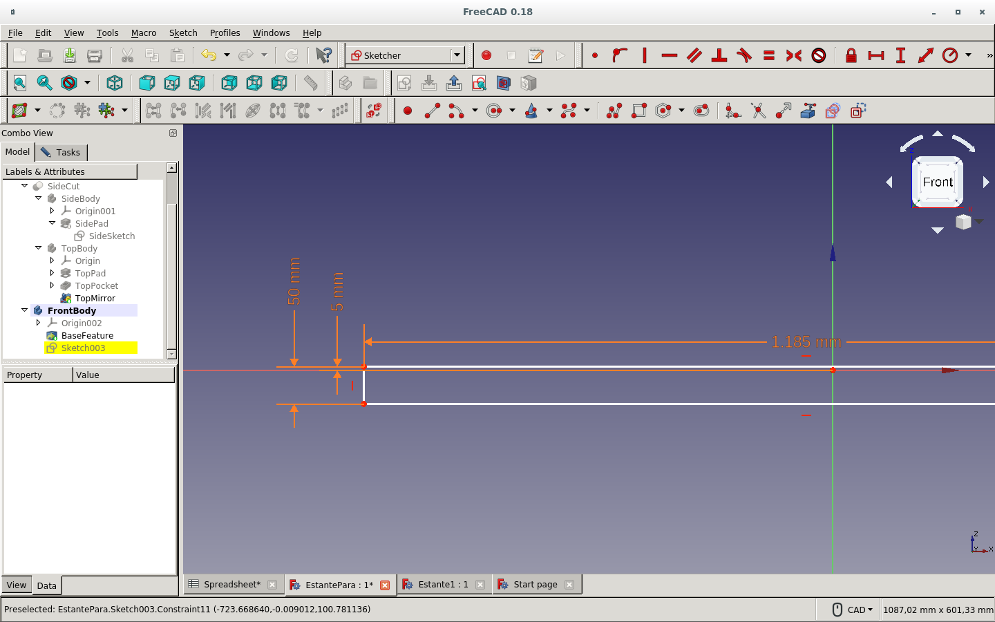
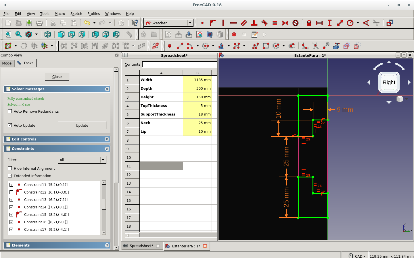
Here I set parametrically the dimension of the dent.
I keep the thickness of the side board on the top board edges.
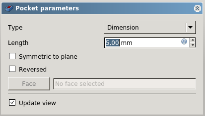
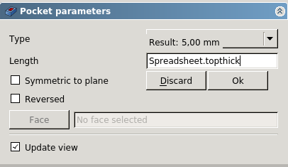
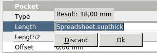
And then make a pocket.
The parameter is the thickness of the side board.

Not the top board thickness!
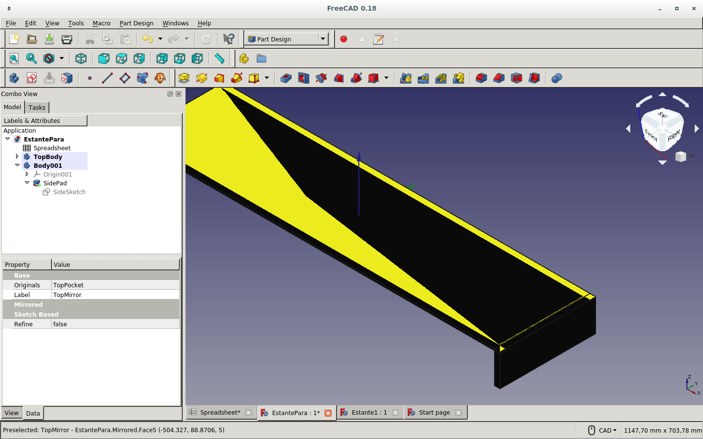
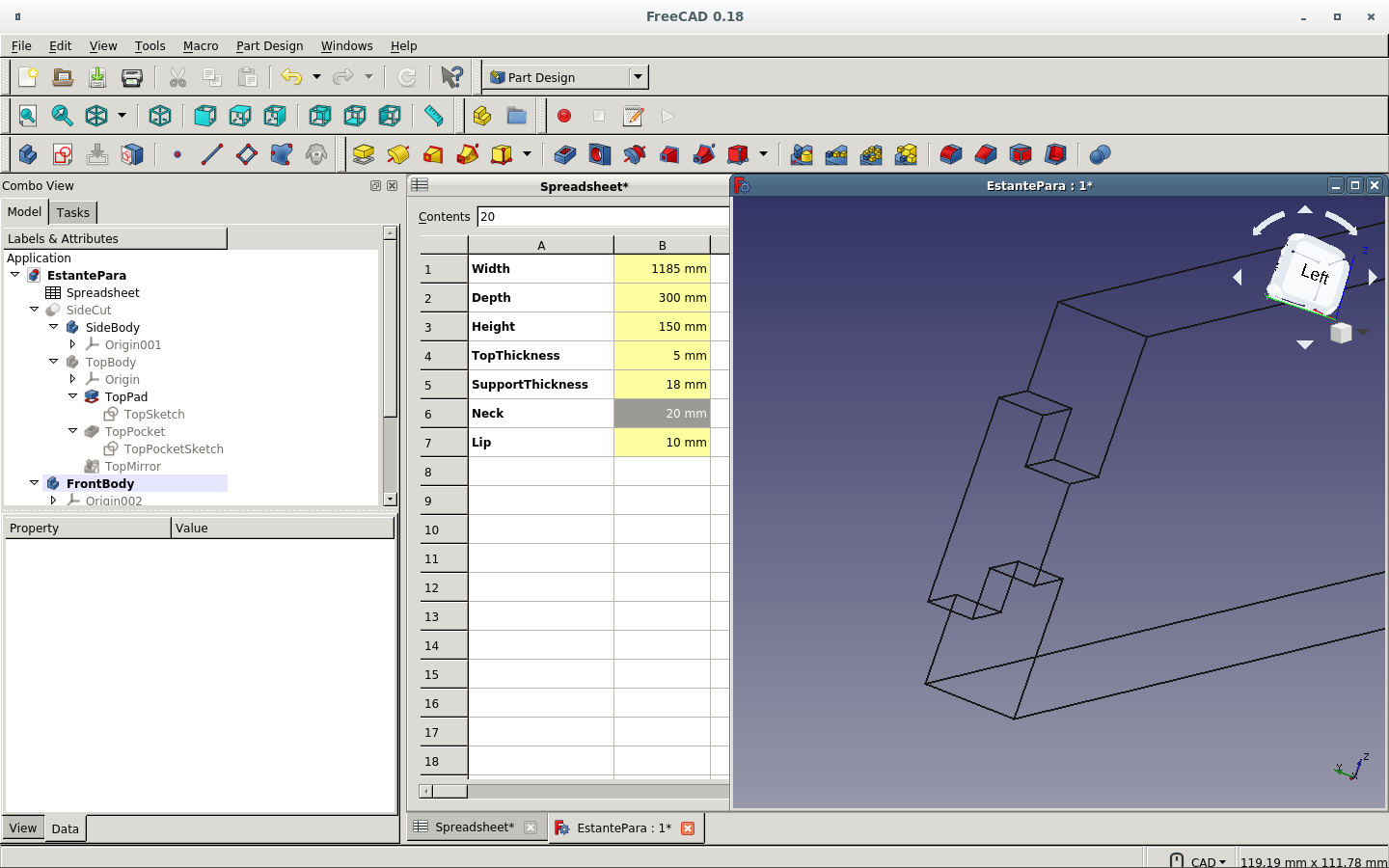
Here is the finished dent on the side of the top board.
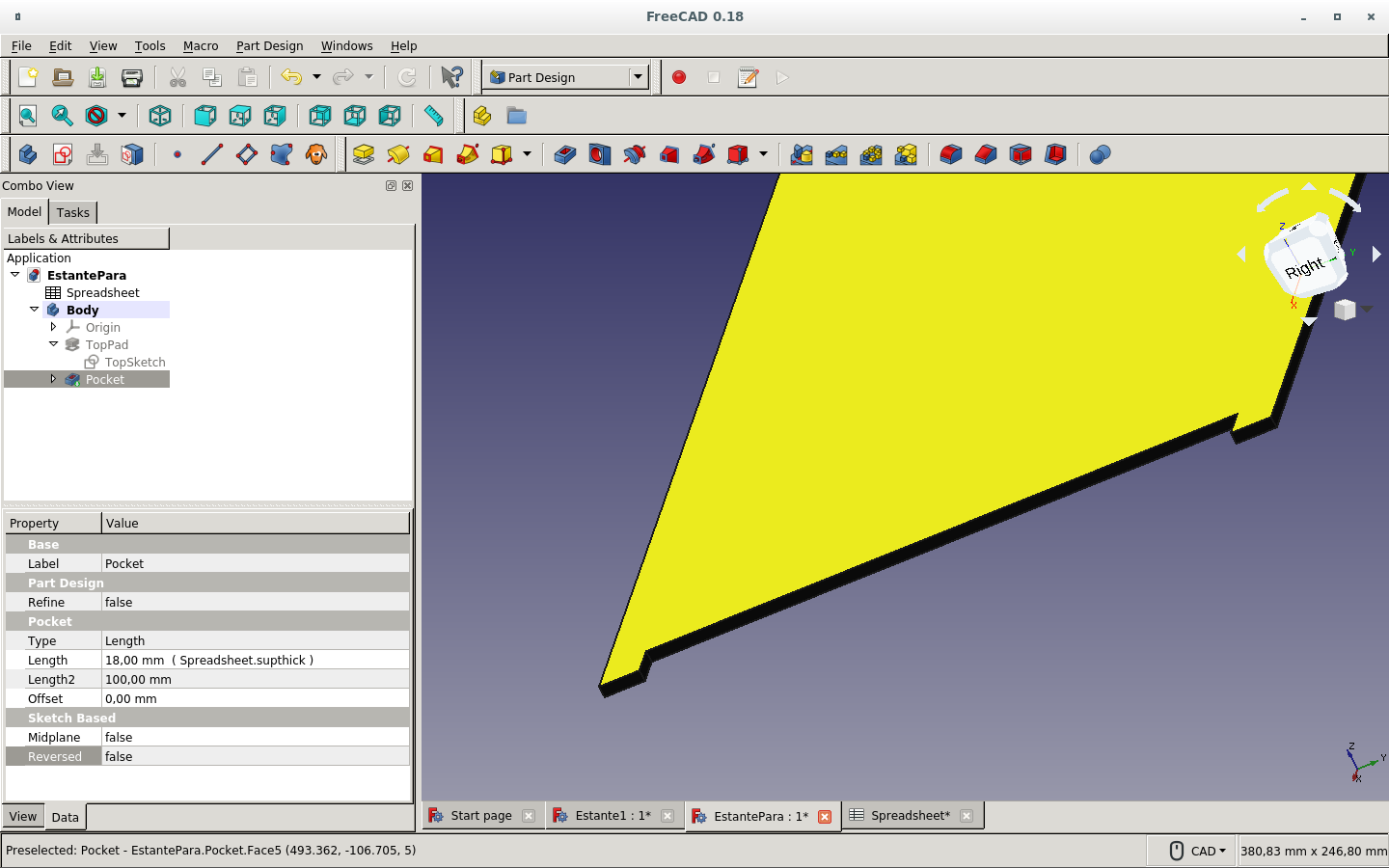
But we have only one side.
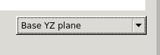
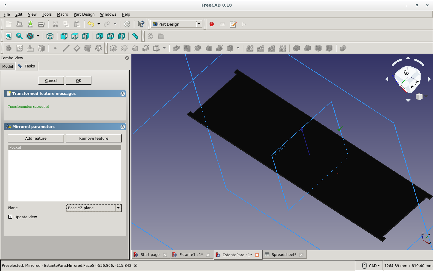
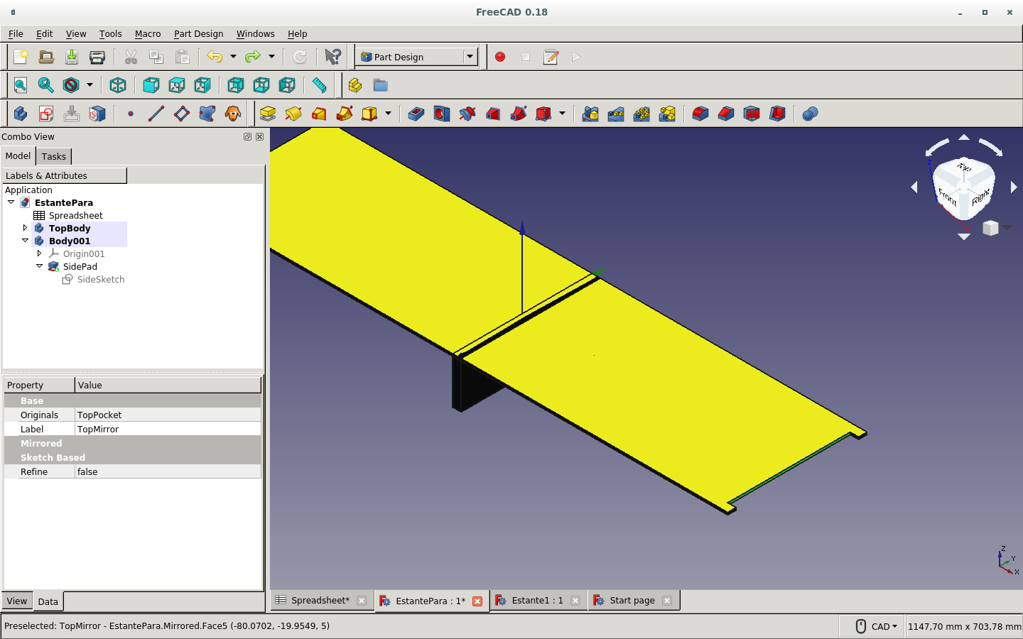
So we make a mirror with the base on the YZ plane.
Here we can see the mirroring action preview.
We make some more changes to the spreadsheet.
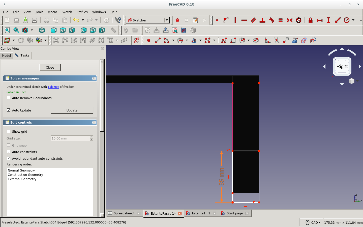
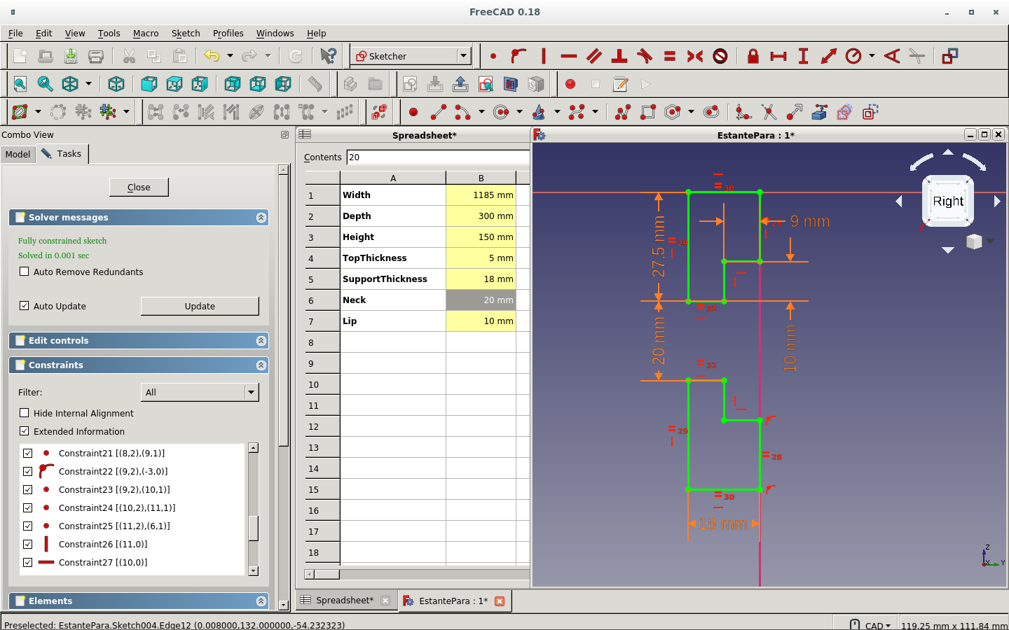
And sketch the side board.
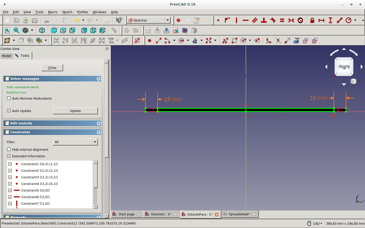
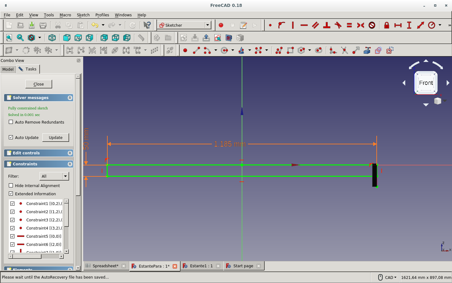
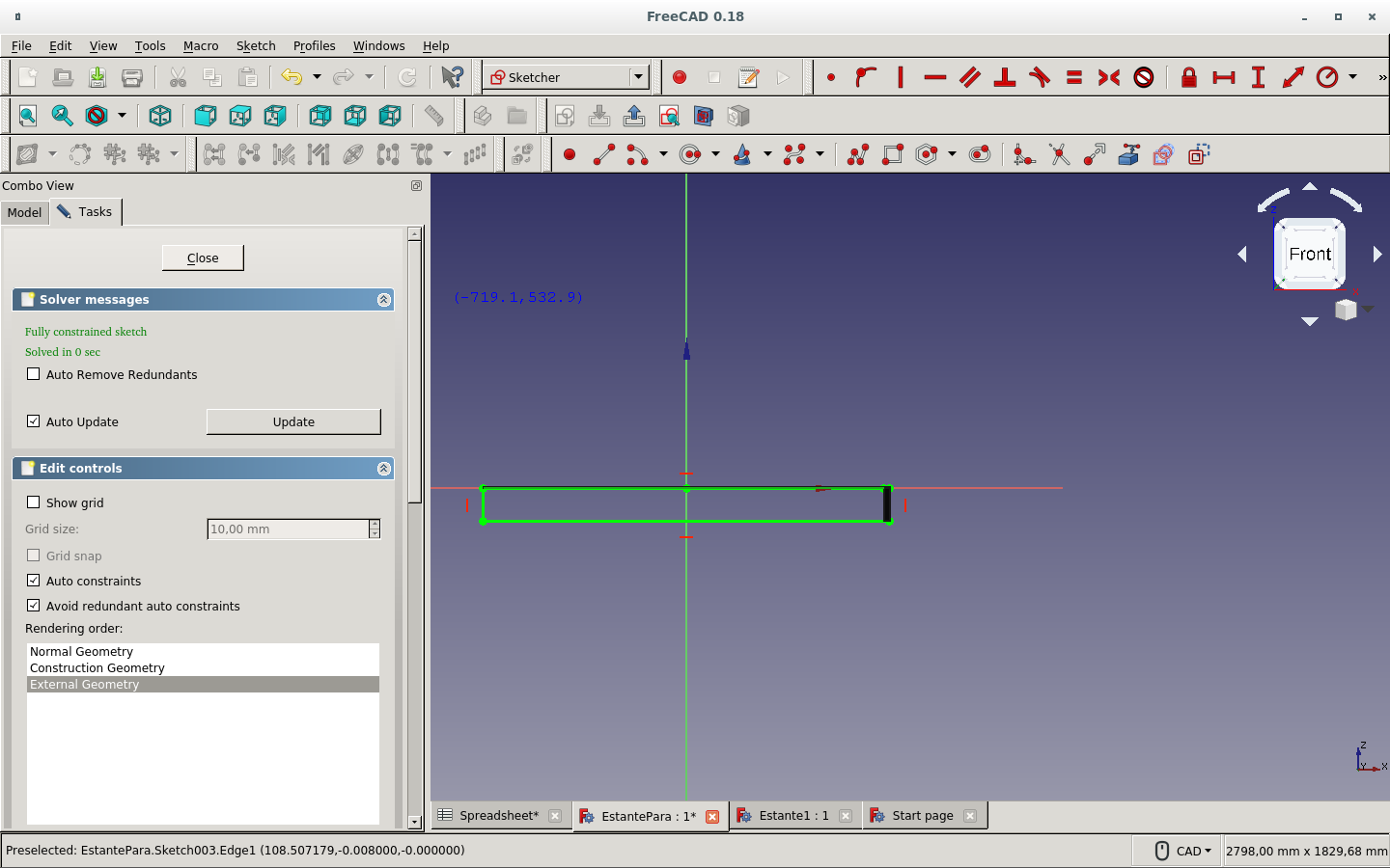
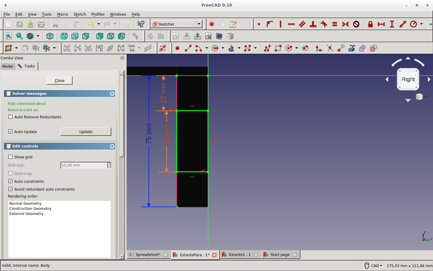
Then we have it fully constrained

with the parameter of the top board thickness.
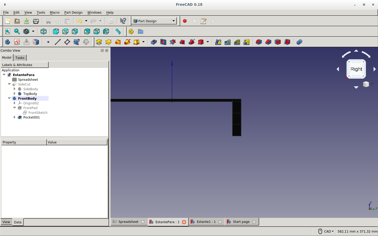
The side board sketch is now level with the surface of the top board. above the horizontal axis.

But it is on the origin and not on the side of the top board.
So we use the Map sketch to face icon for moving this sketch to the edge of the top board.

We refresh.

And see the movement of the side board to its place.
We modify its name for better reference.
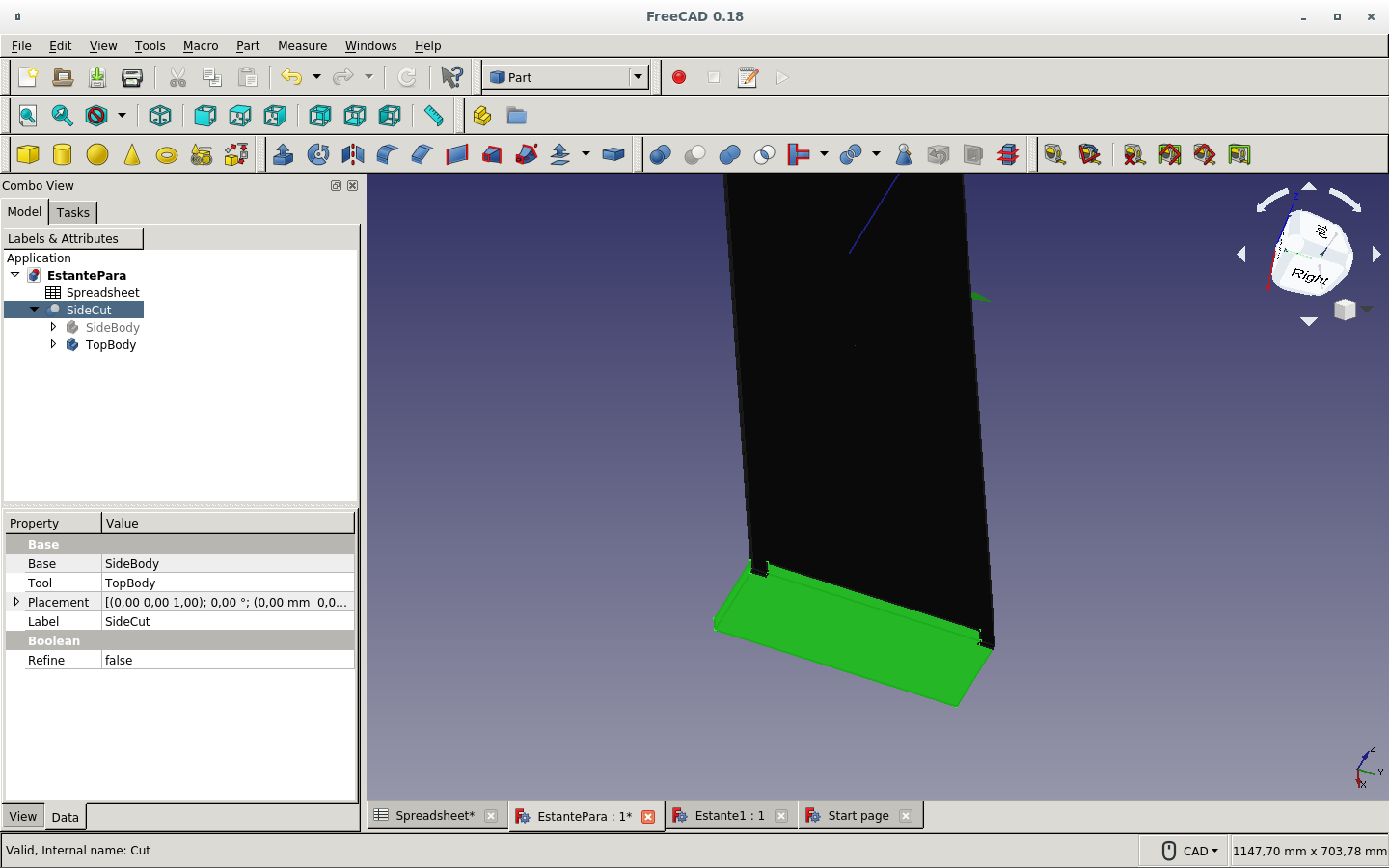
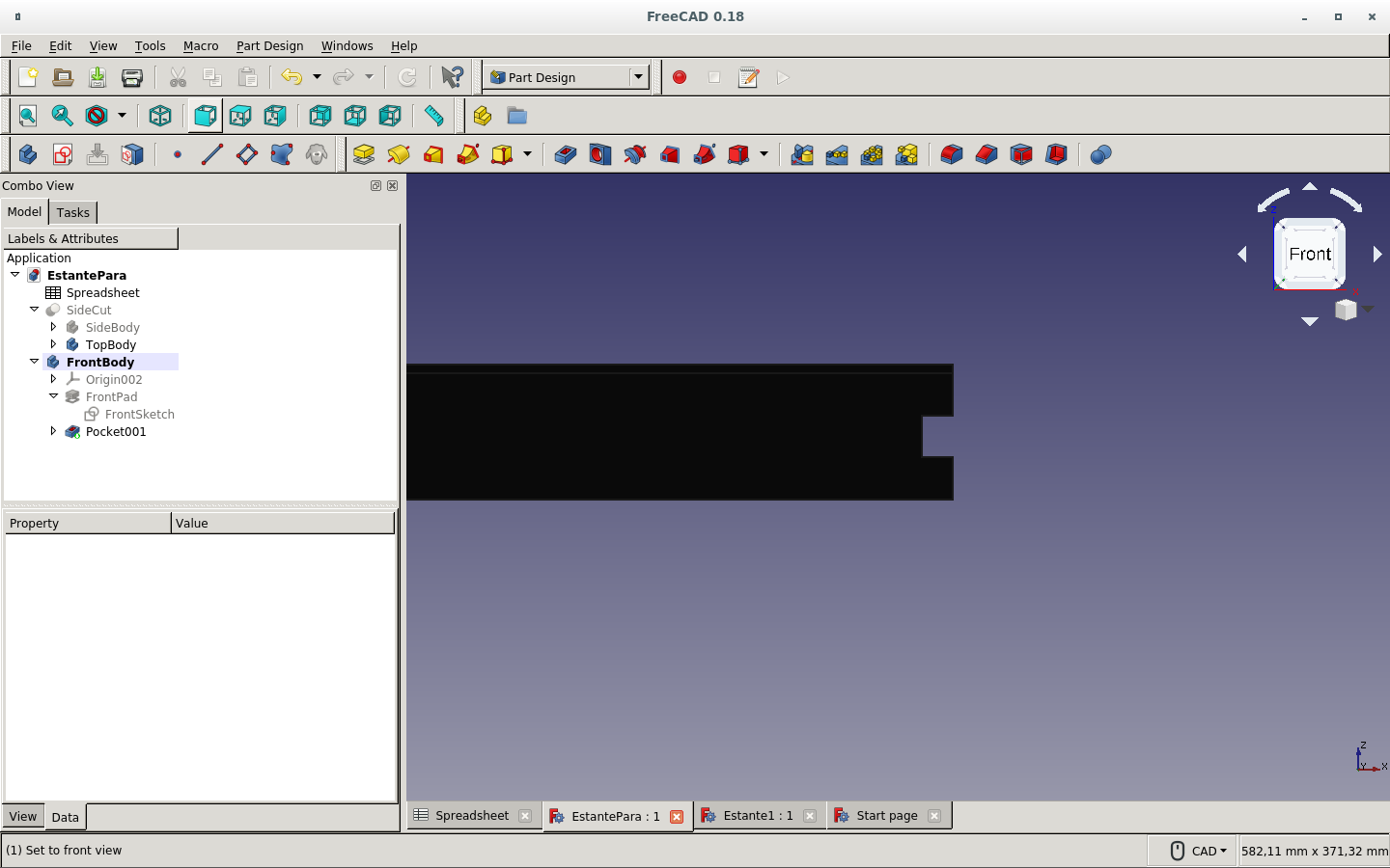
We can see the intersection of the dent on the top piece with the side piece.
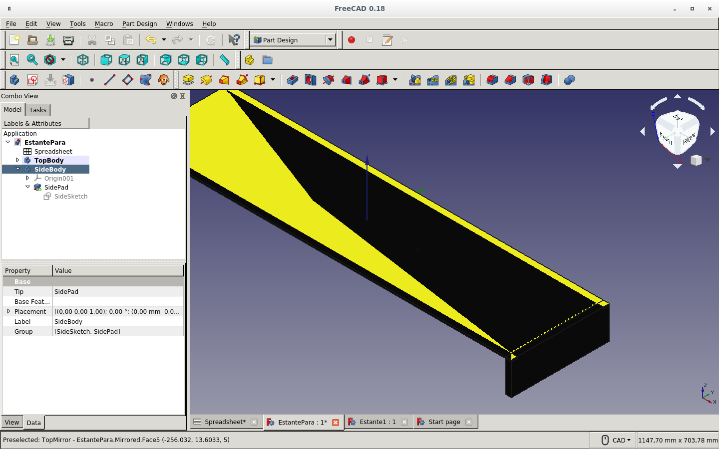
Selecting the side board and then, with the control key pressed, selecting the top board...

And then making a boolean cut with the icon which is lighter on this picture. (If chosen in that order, the side board is cut by the top board.)
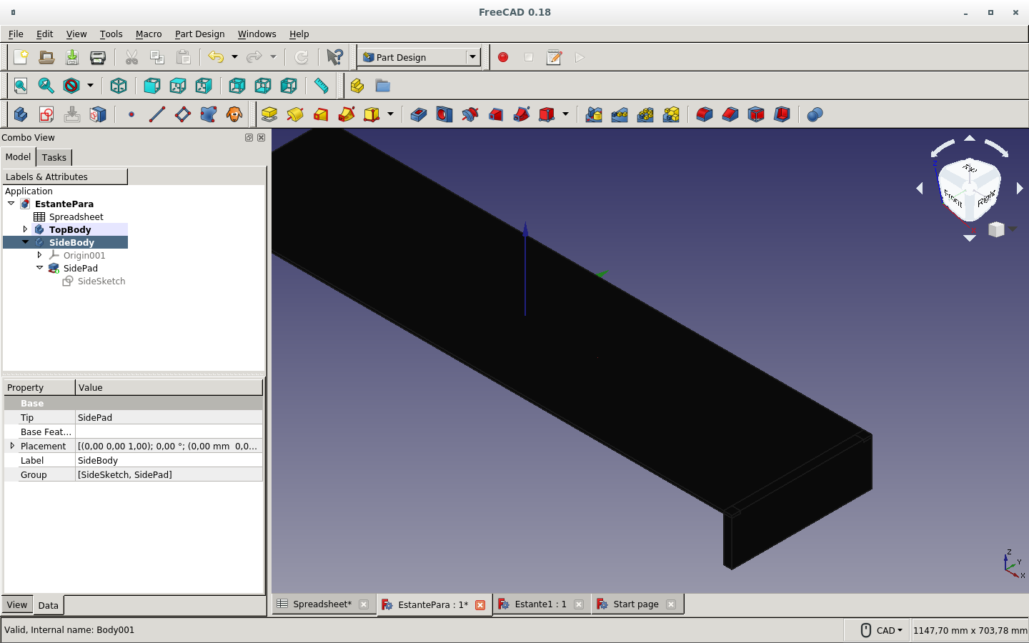
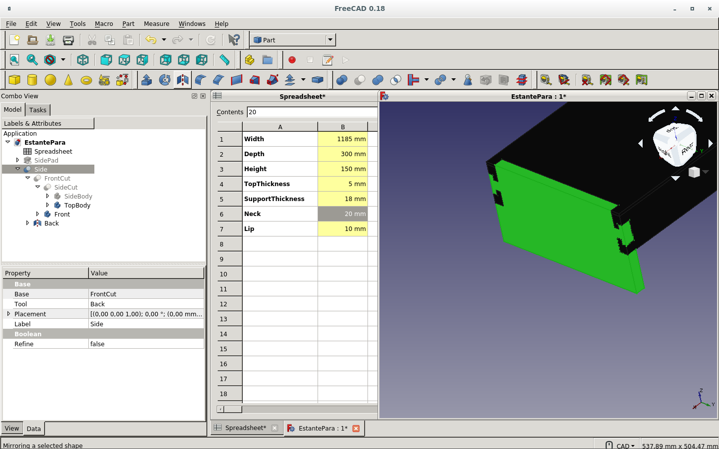
The side board can be observed after the cut operation with the top board visible.
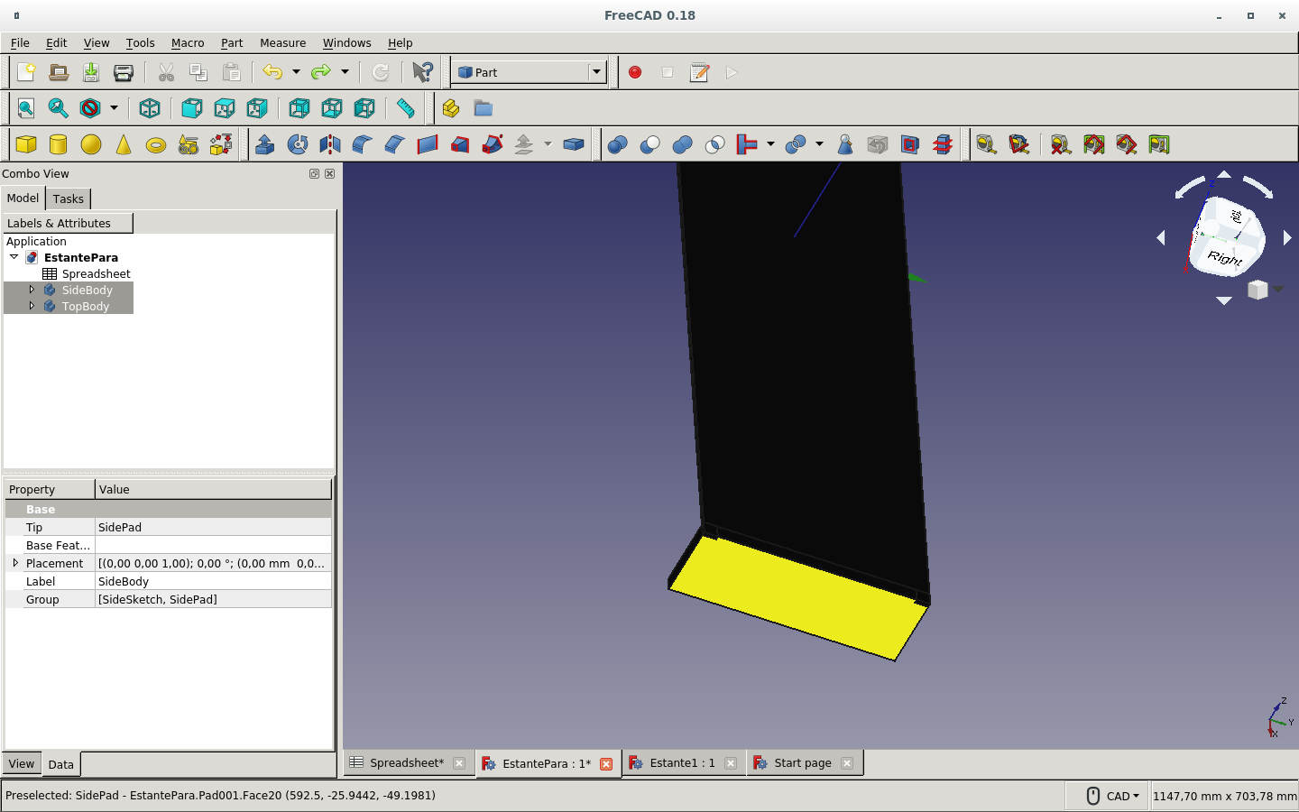
with the top board invisible.
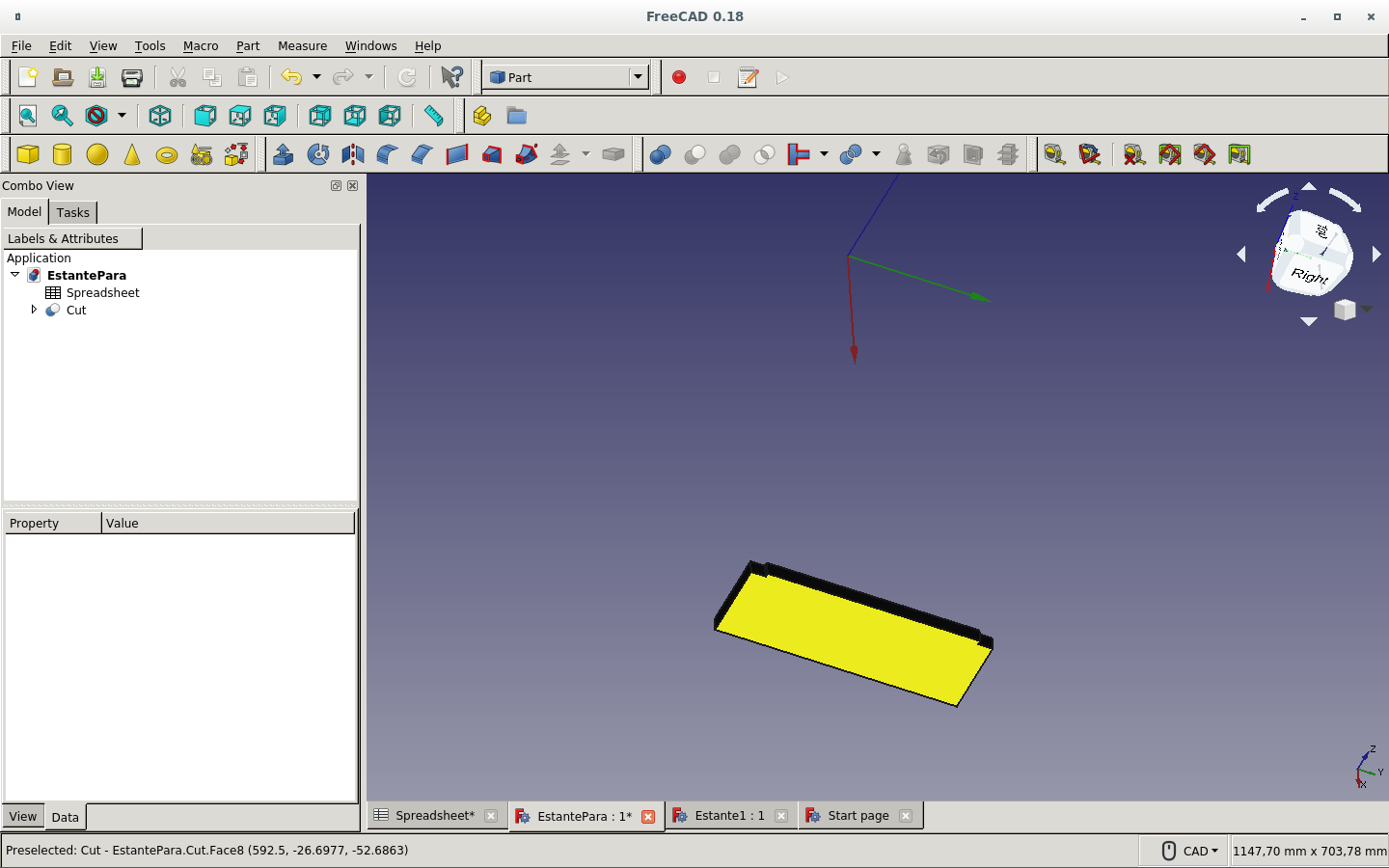
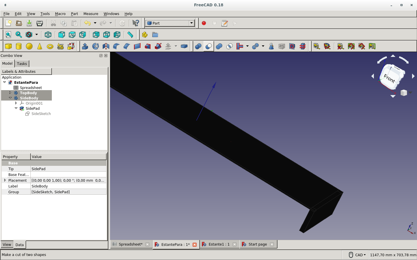
In another color.
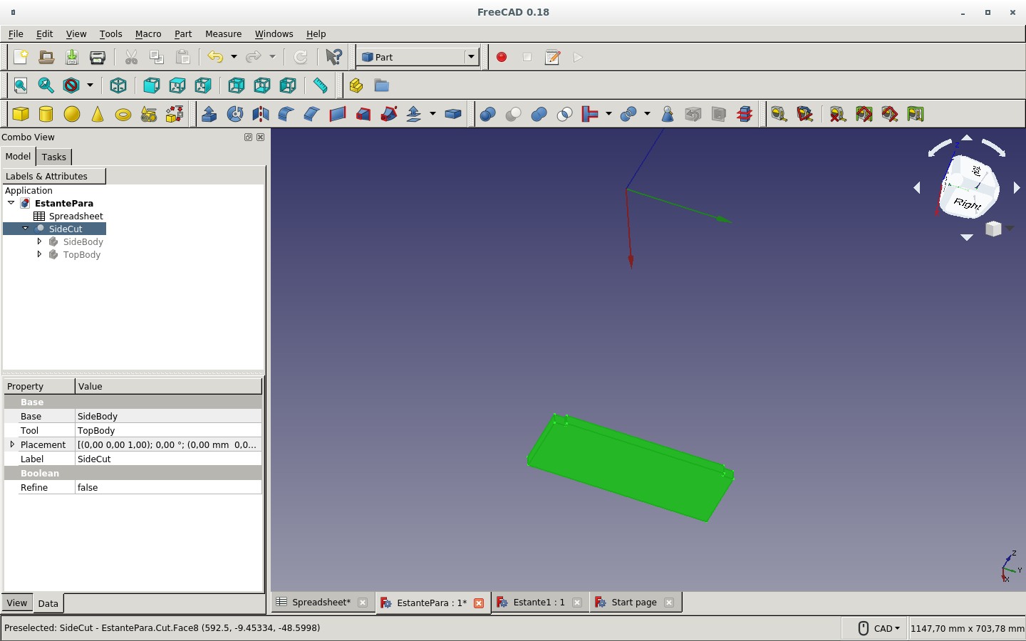
In contrast with both boards visible.
Mirror operation to duplicate the side board on the other side.
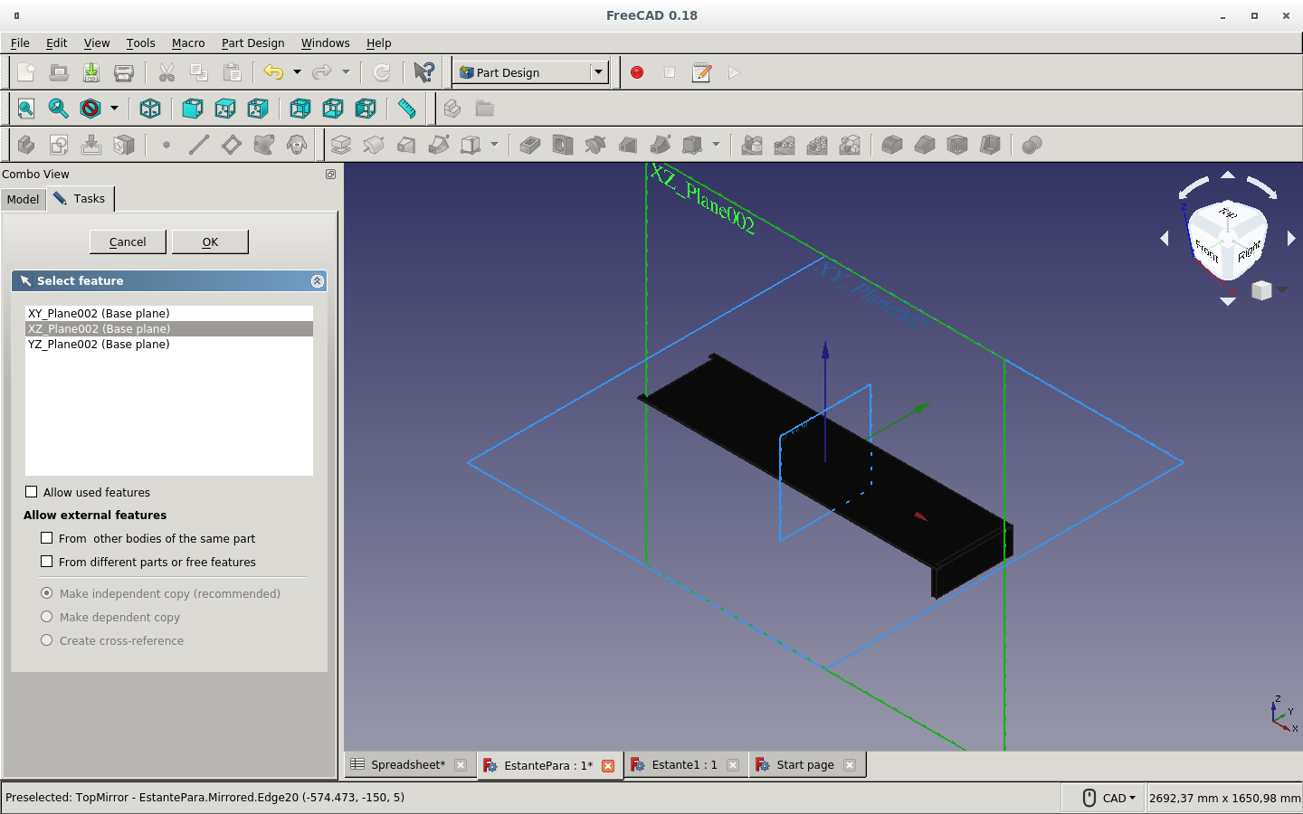
Defining the distance of the mirror operation as the width of the shelf.
But it is really only half the width from the mirror axis.
Front board sketch.
The front board is to be cut by the top board? It will be lowered on the next step.
One constraint remains to be defined.
Full constriction attained after linking the front board's top right corner with the top board's lower corner via the Coincident constraint icon.
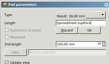
Defining parametrically the pad (solid) thickness.
We can observe the new solid board on the axis created by the padding on the sketch.
So we need to used the Map sketch to face icon. It asks which sketch must the face be mapped to.
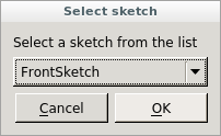
The face and the sketch are to be confirmed.
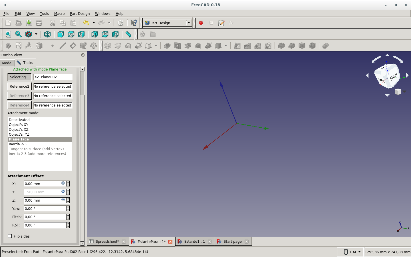
I define the points on the sketch and on the face to fix the constraints. The sketch is then fully constrained.
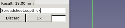
We make a padding to make the front board. Then parametrically define the thickness from the spreadsheet.
I made a new sketch to try again.
And defined the parameters.
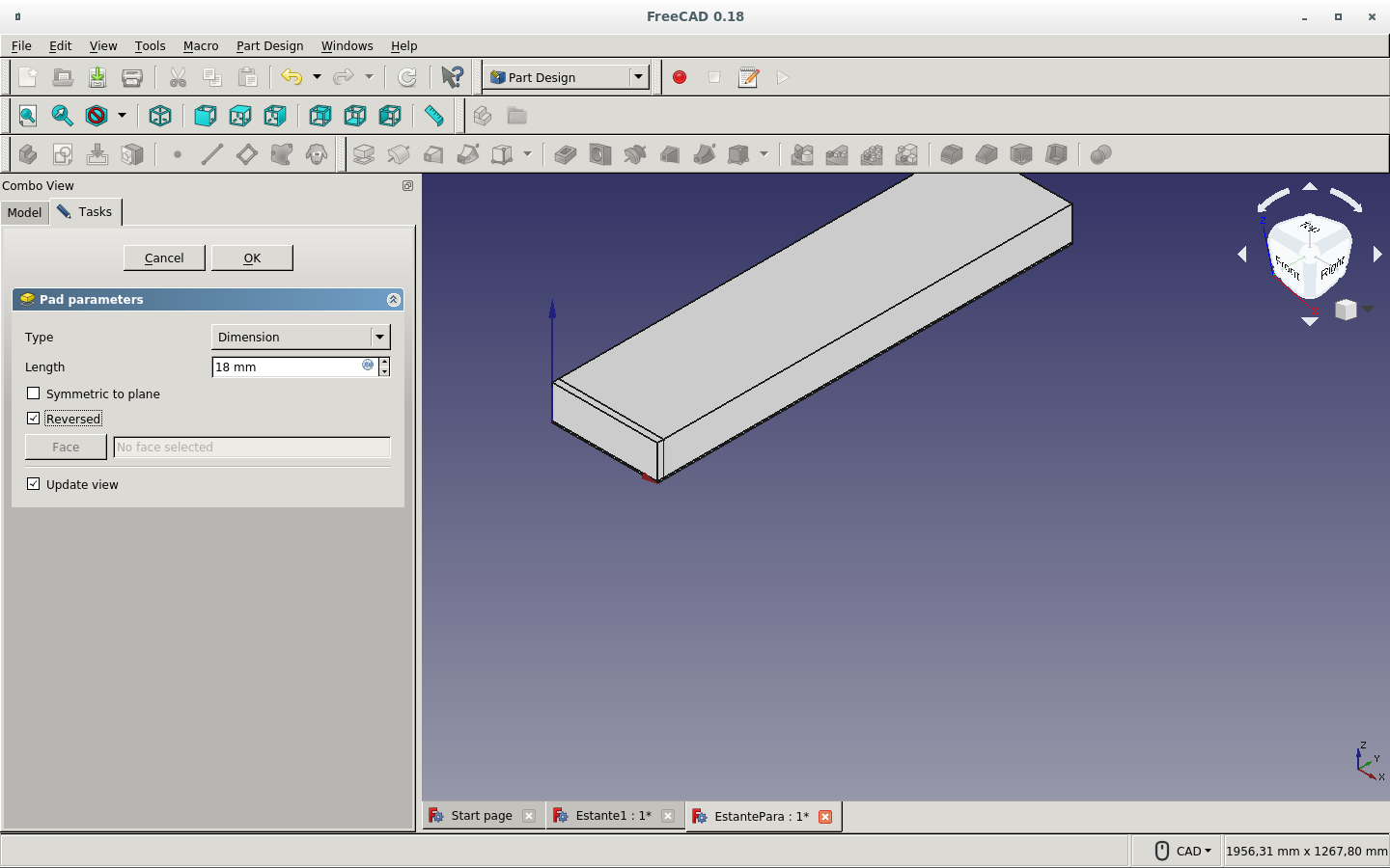
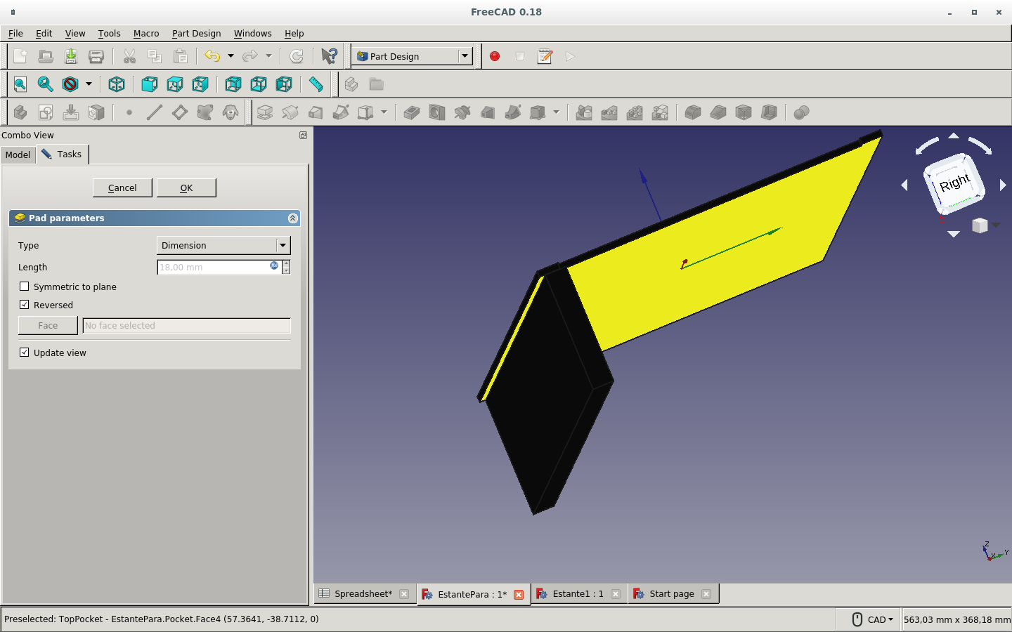
Then I made a pad. I am testing with reversing the side of the pad.
These are the constraints for the side panel sketch.
And these are for the front panel sketch.
I define a sketch for the cut on the side board which will belong to the press-fit.
And set the parameters to fully constrain the sketch.
I cut this piece with a pocket operation for the press-fit. But it is not the shape it should be.
Now I define the parameters of the shape as neck and lip.
This is the press-fit I made on the side board to fit with the front board.
I go back to the front board.
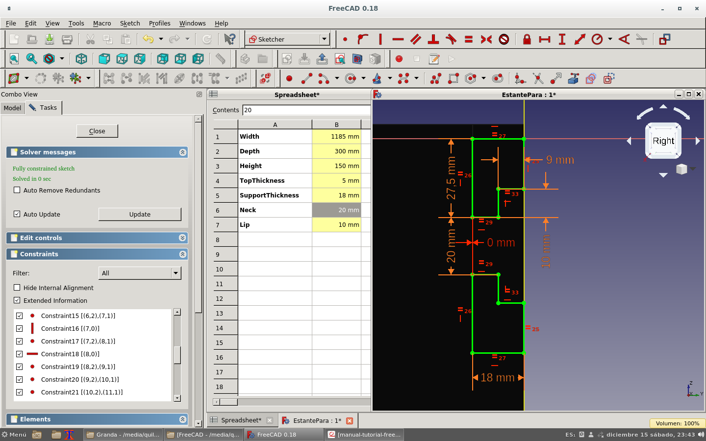
And edit the sketch of the press-fit cut with the spreadsheet to feed the parameters.
The changed values on the spreadsheet change the values on the sketch.
Both figures must vary with the thickness of the side board; hence the horizontal distance of 0mm between parallel pieces.
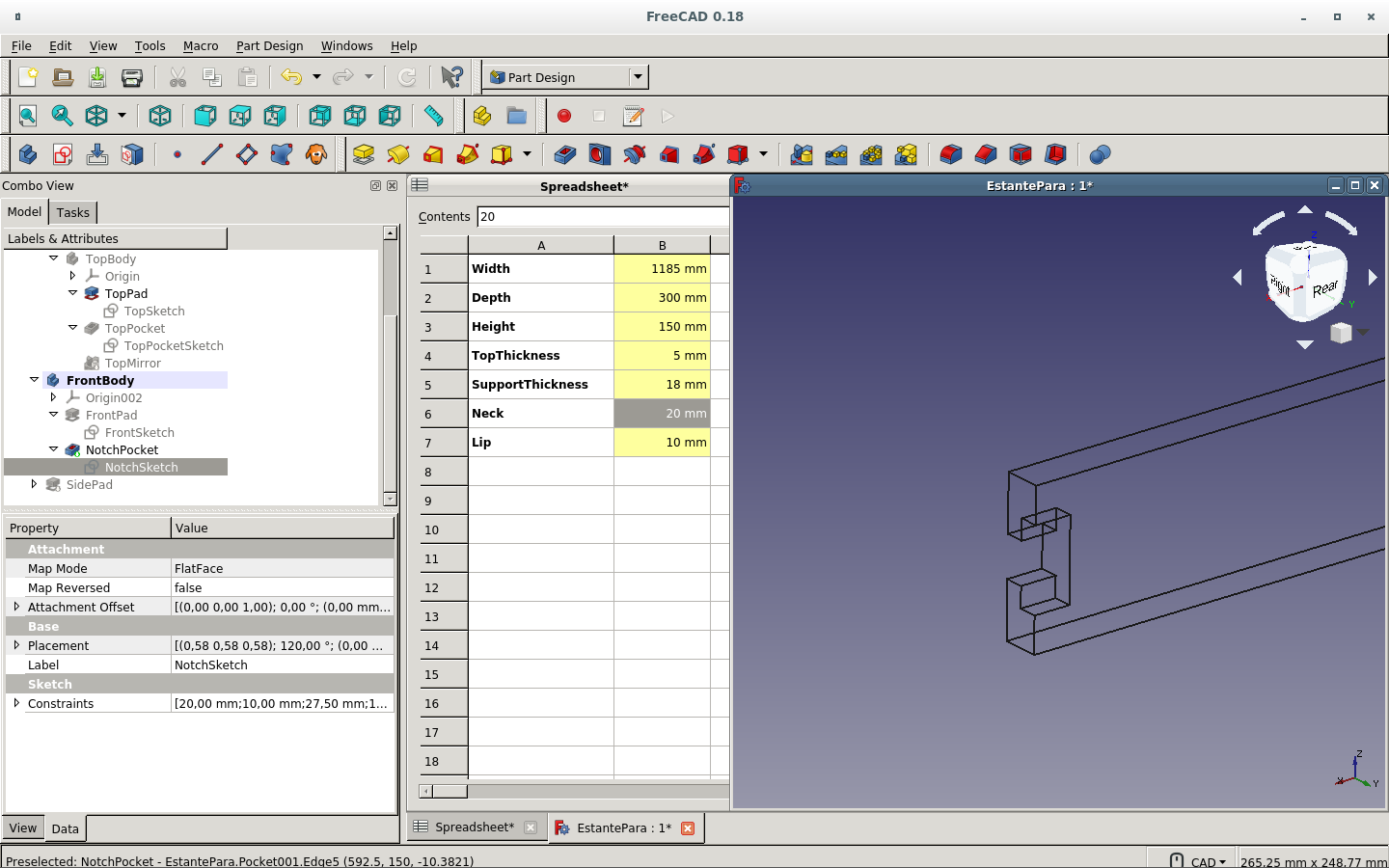
Here is the pocket produced.
But it is backwards. So I change the sketch.

We gut this final front board press-fit.
And this is the integration with the side piece.
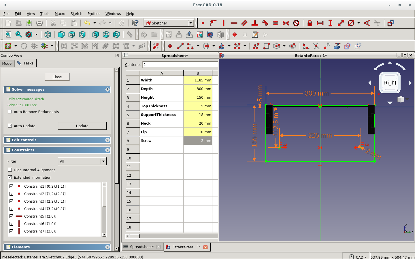
Parametrizing the screw holes on the side piece. They should be equally distant from the center
So the side board is complete and the front and back boards have a press-fit cut...on one side.
Now I mirror the side board.
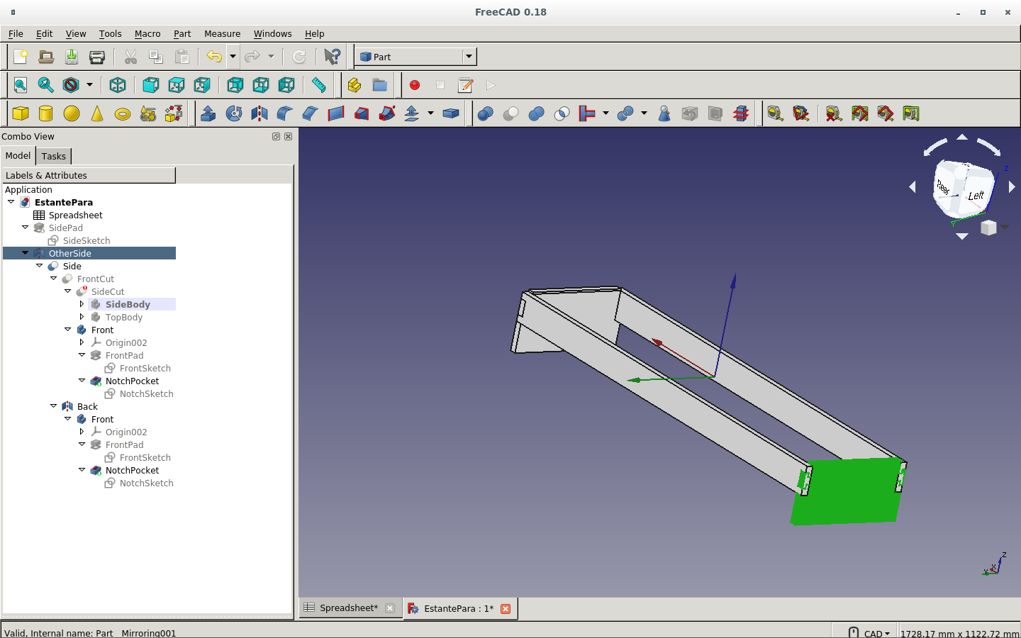
I make the cut on both pieces with the new mirror (OtherSide).
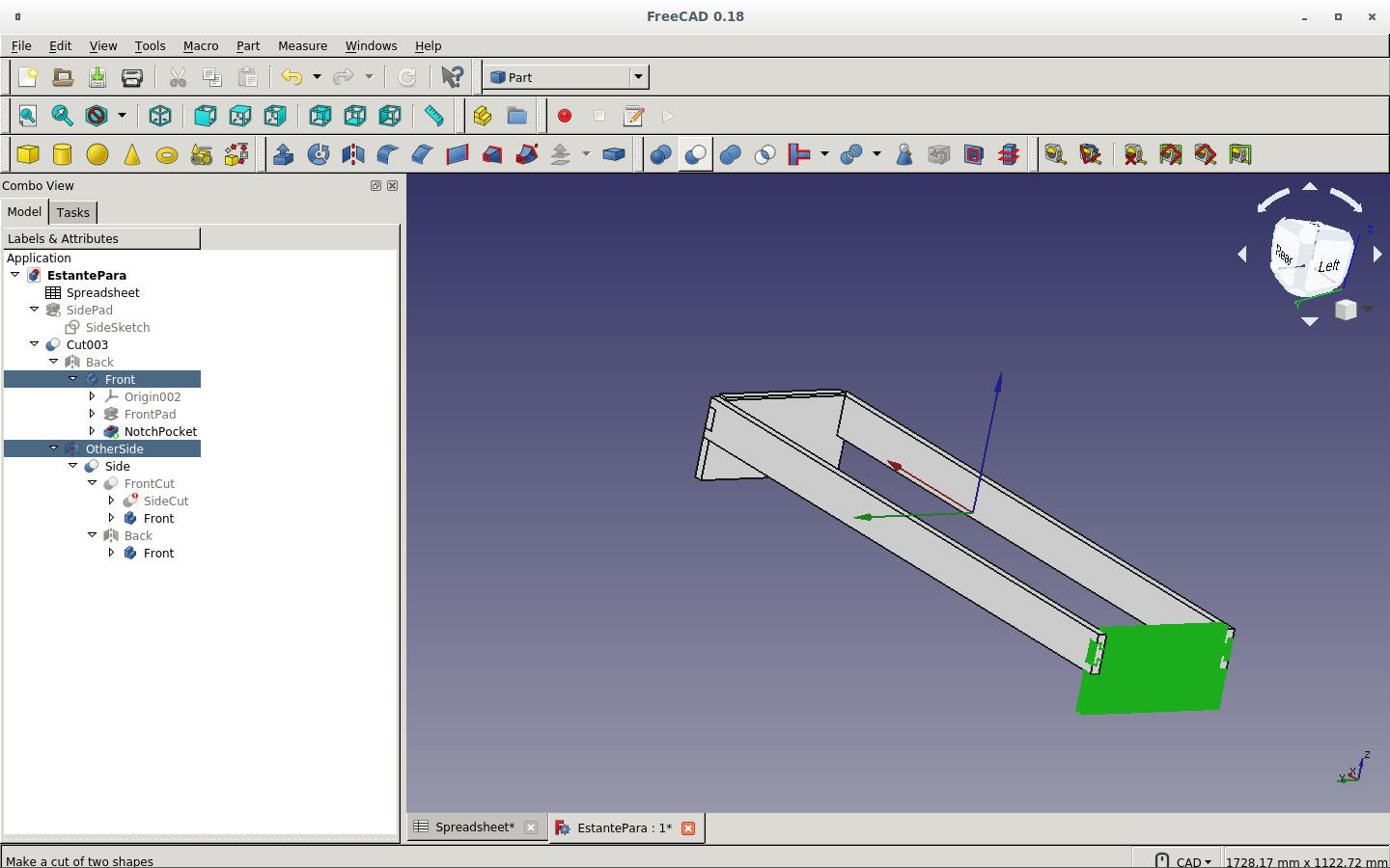
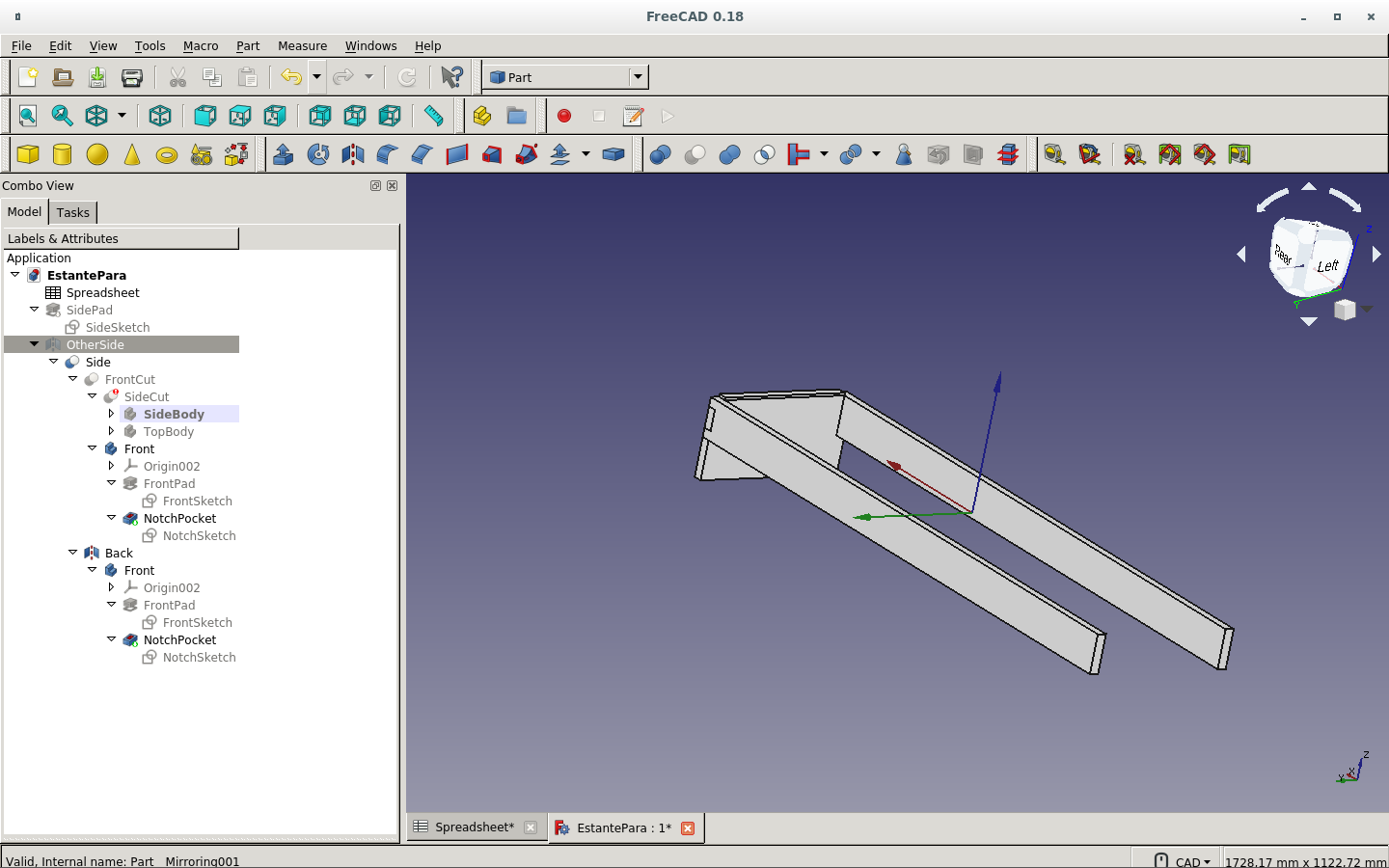
Here are the front and back boards shown with the new press-fit cuts.
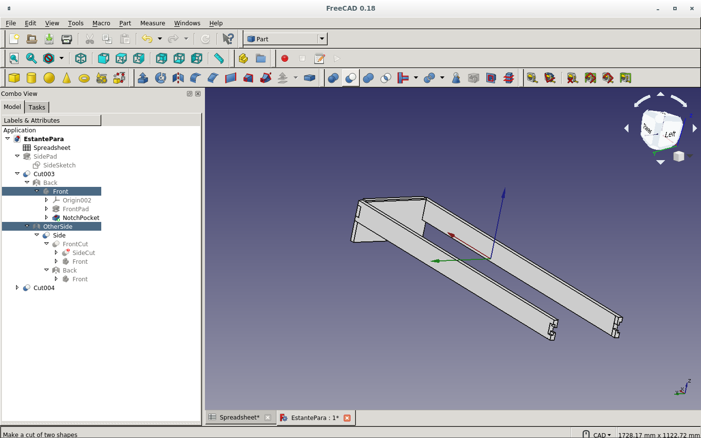
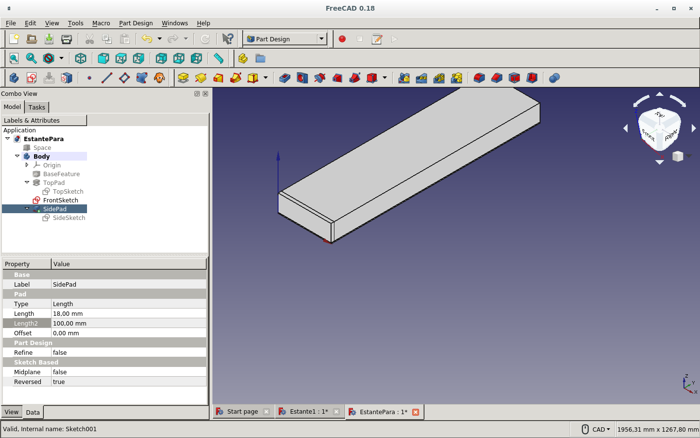
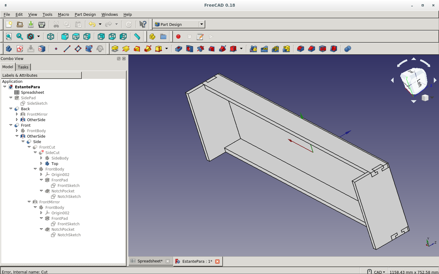
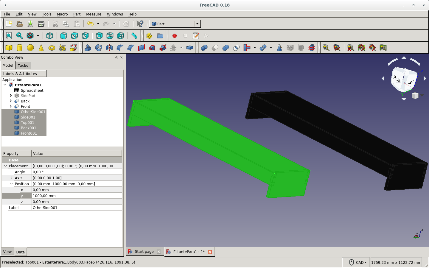
These are the finished support boards: Side, OtherSide, Front and Back.
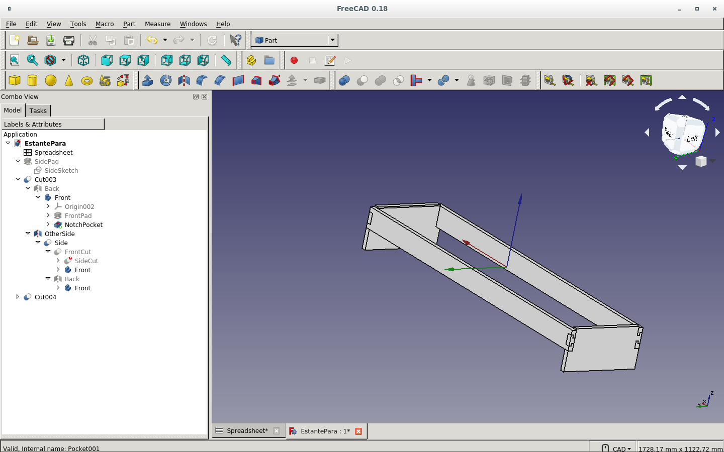
And here they are with the top board, which is the shelf.
These are the final spreadsheet parameters.
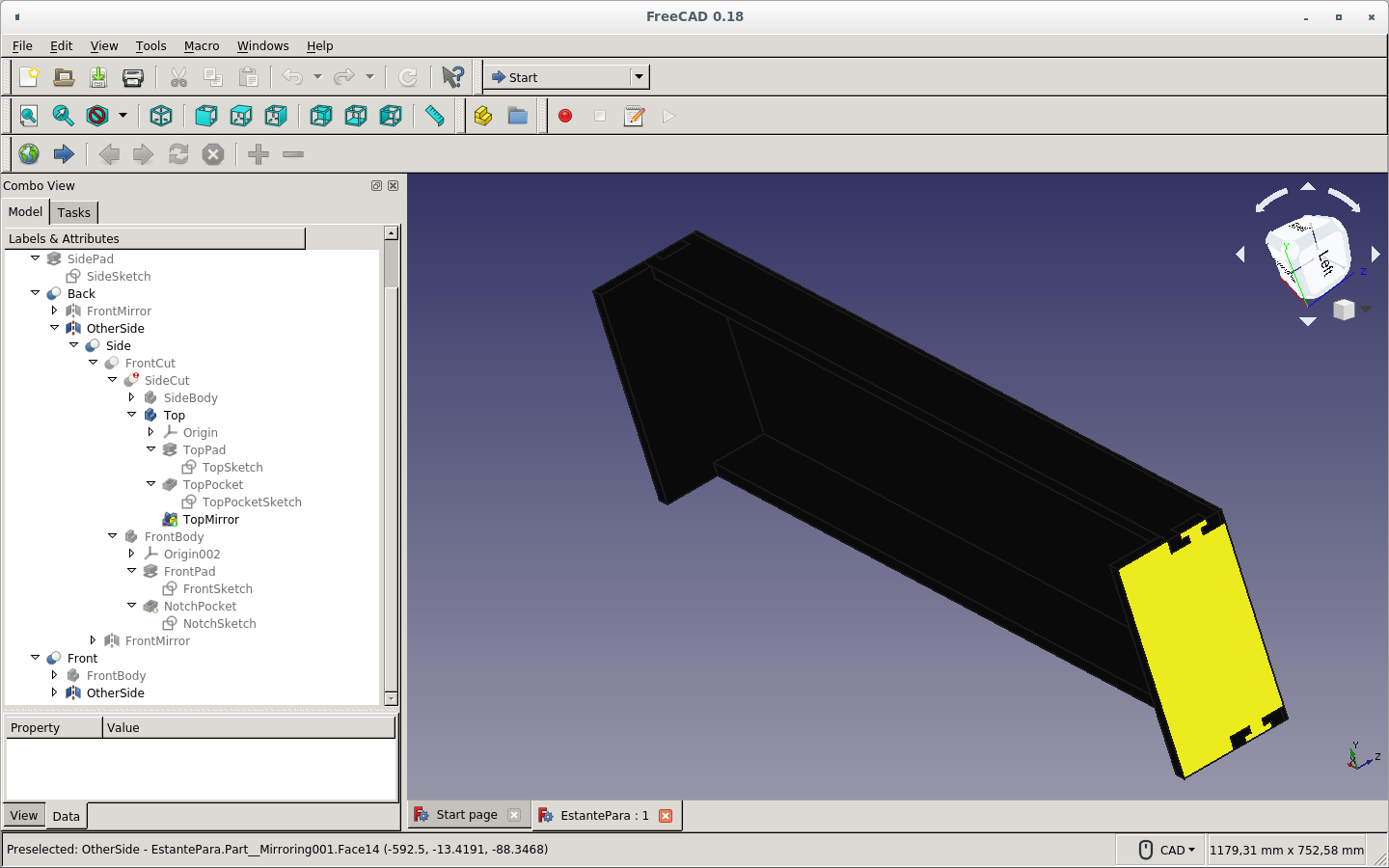
One more view of the finished work.
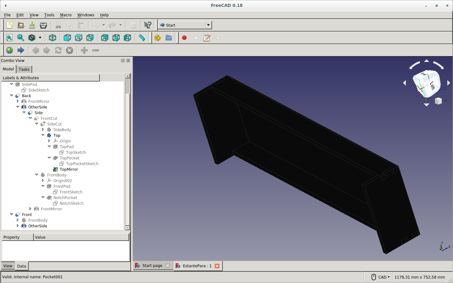
Yet another view.
Simple copy of the work in order to make all boards on the same plane. It is something to take into account that this copy will not keep the parameters. But I cannot make the new piece turn without turning the original one.
Showing only the copies of the boards.
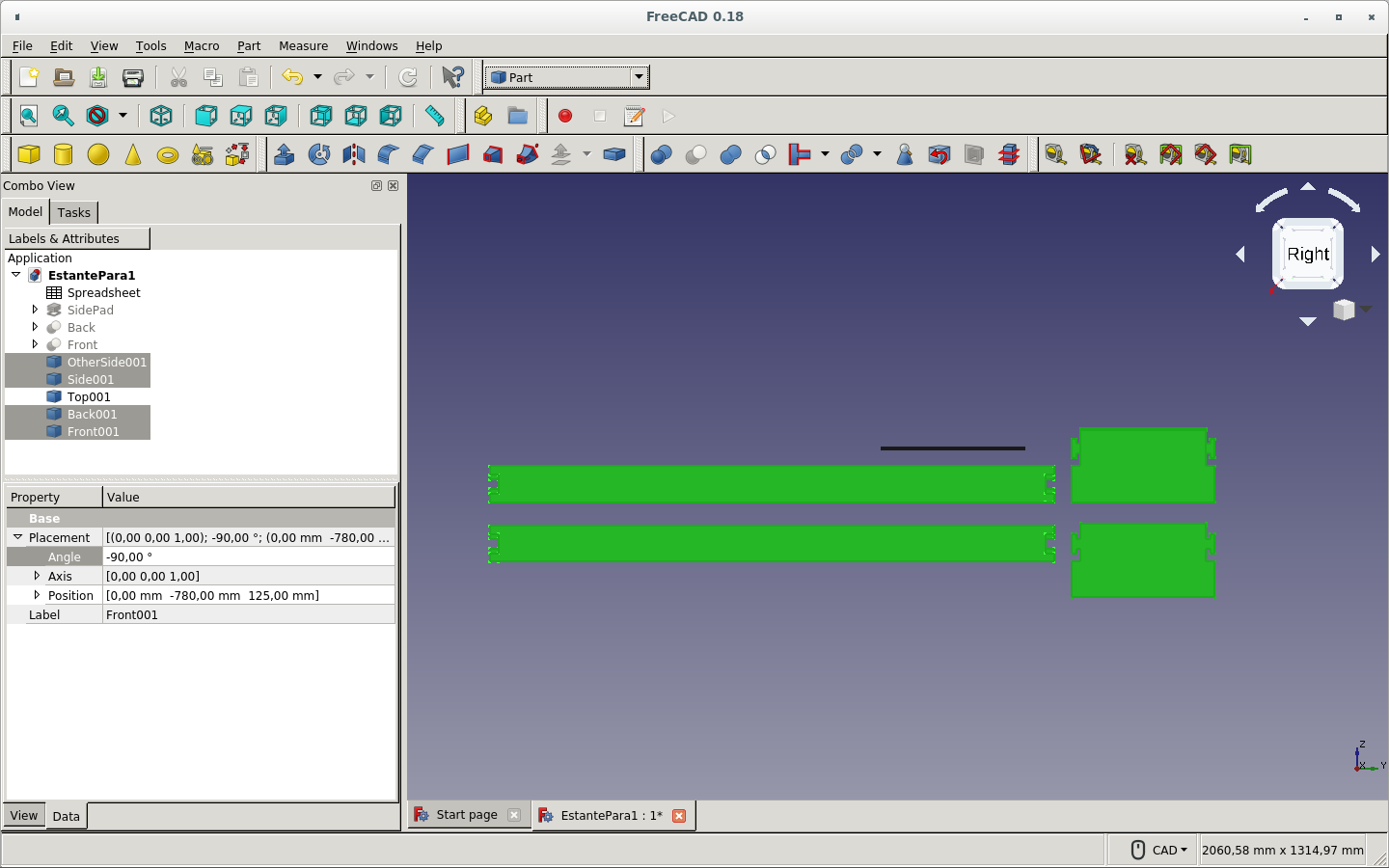
I turned each piece separately by changing the axis and the angle until all boards became parallel.
I made a compound piece for making the paths. This was not necessary on version 0.18.
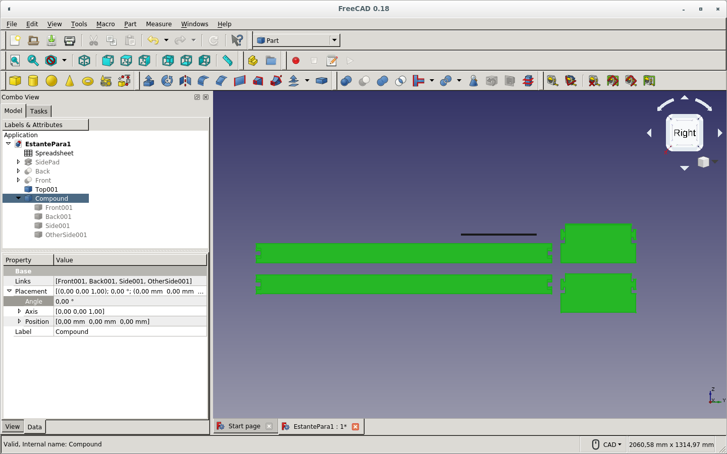
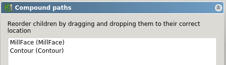
Changed the arrangement.
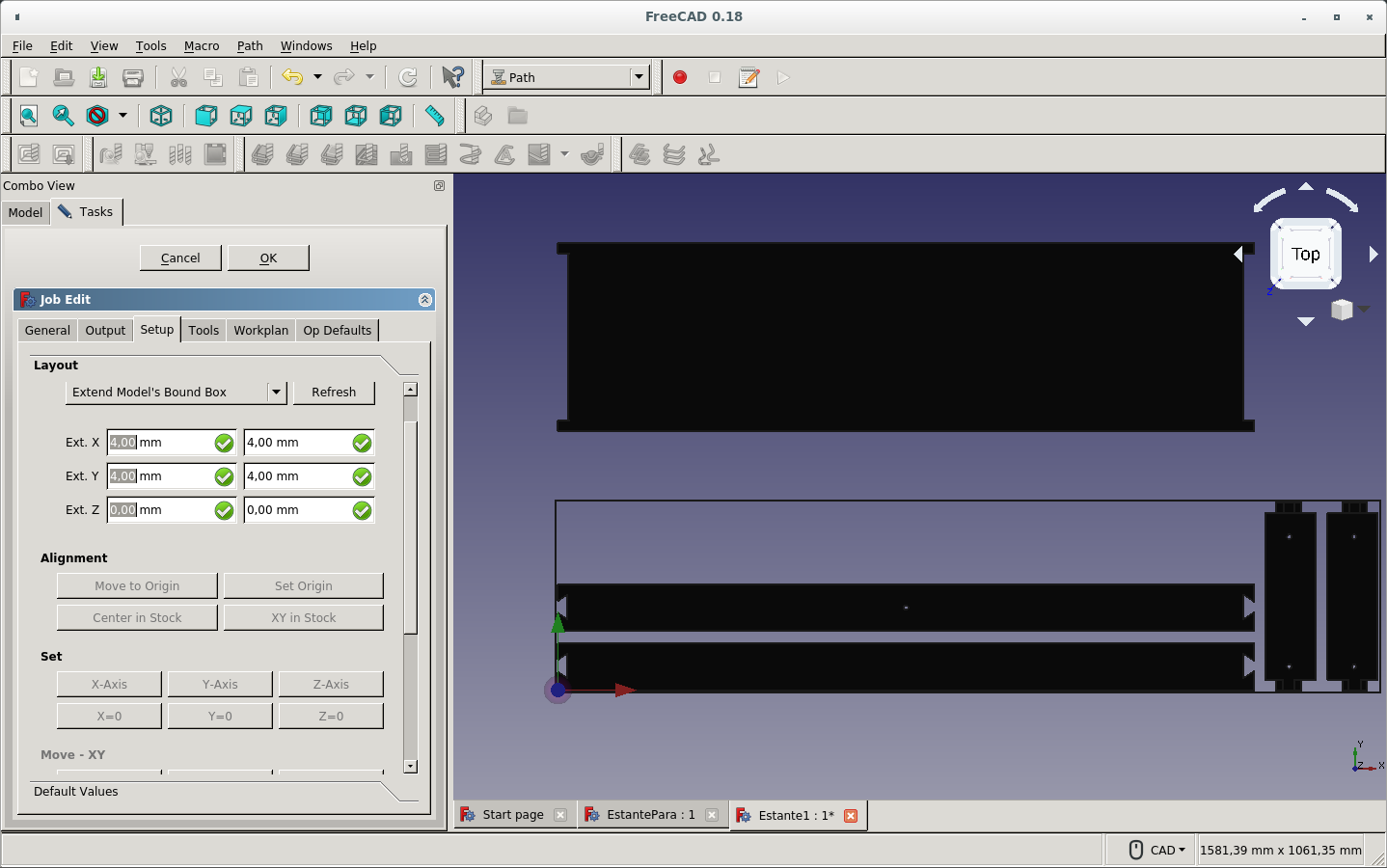
Switched to the Path workbench and created a new path job. I selected the Compound model I just created.
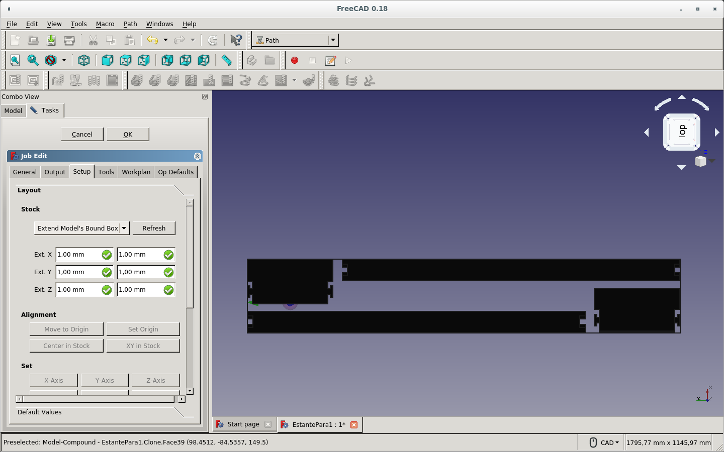
Selected Extended Medel's Bound Box as the stock.
Changed the Gcode output file to be save on the FreeCAD file directory and with the name of the FreeCAD file plus 18.gcode
Changed the name of the job.
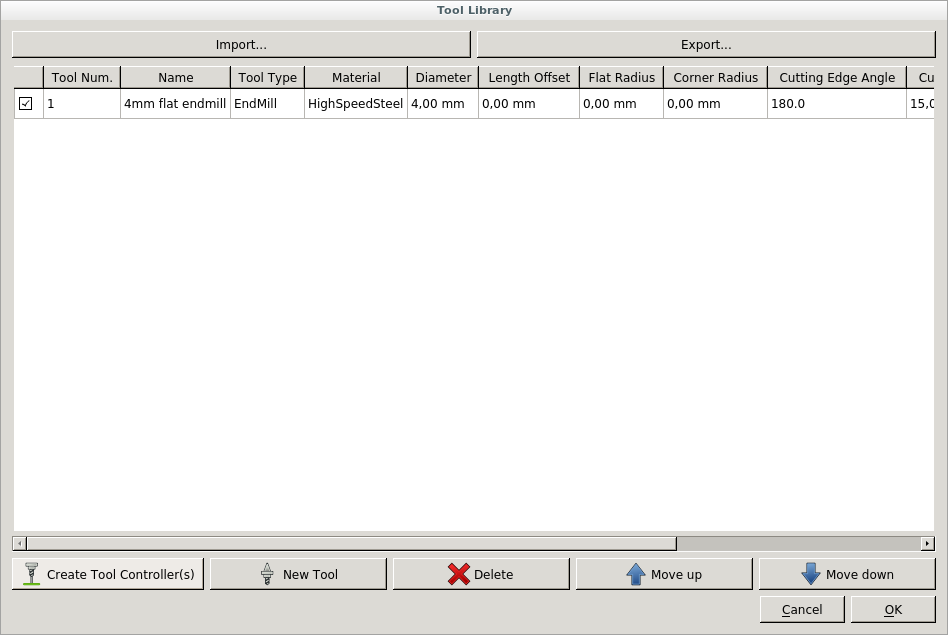
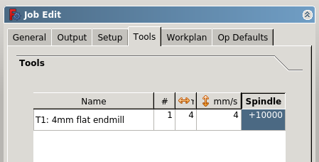
Added a new tool controller.
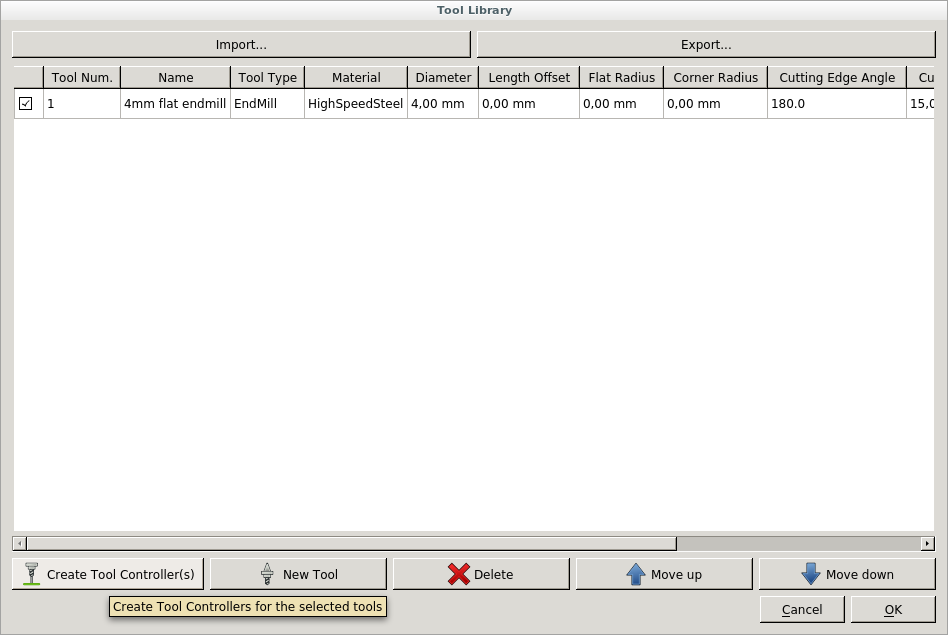
Created a tool controller for the job by selecting the 4mm flat endmill tool.
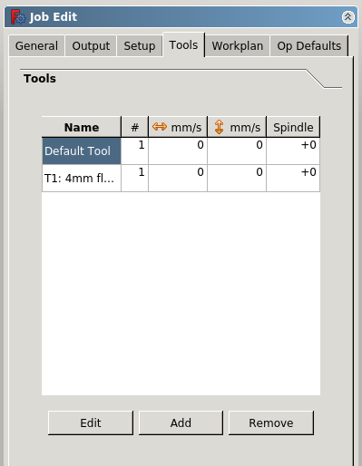
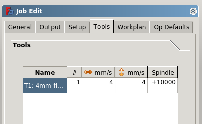
Deleted the default controller and set the horizontal feed, vertical feed and spindle speed for my new controller.
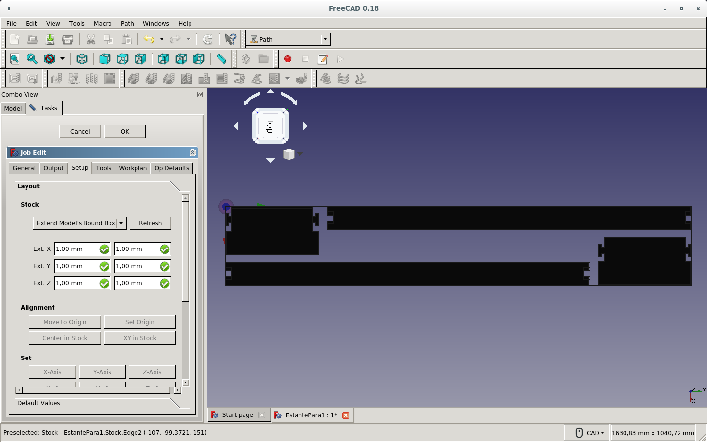
Set the Bound Box extension on the Z axis to none.
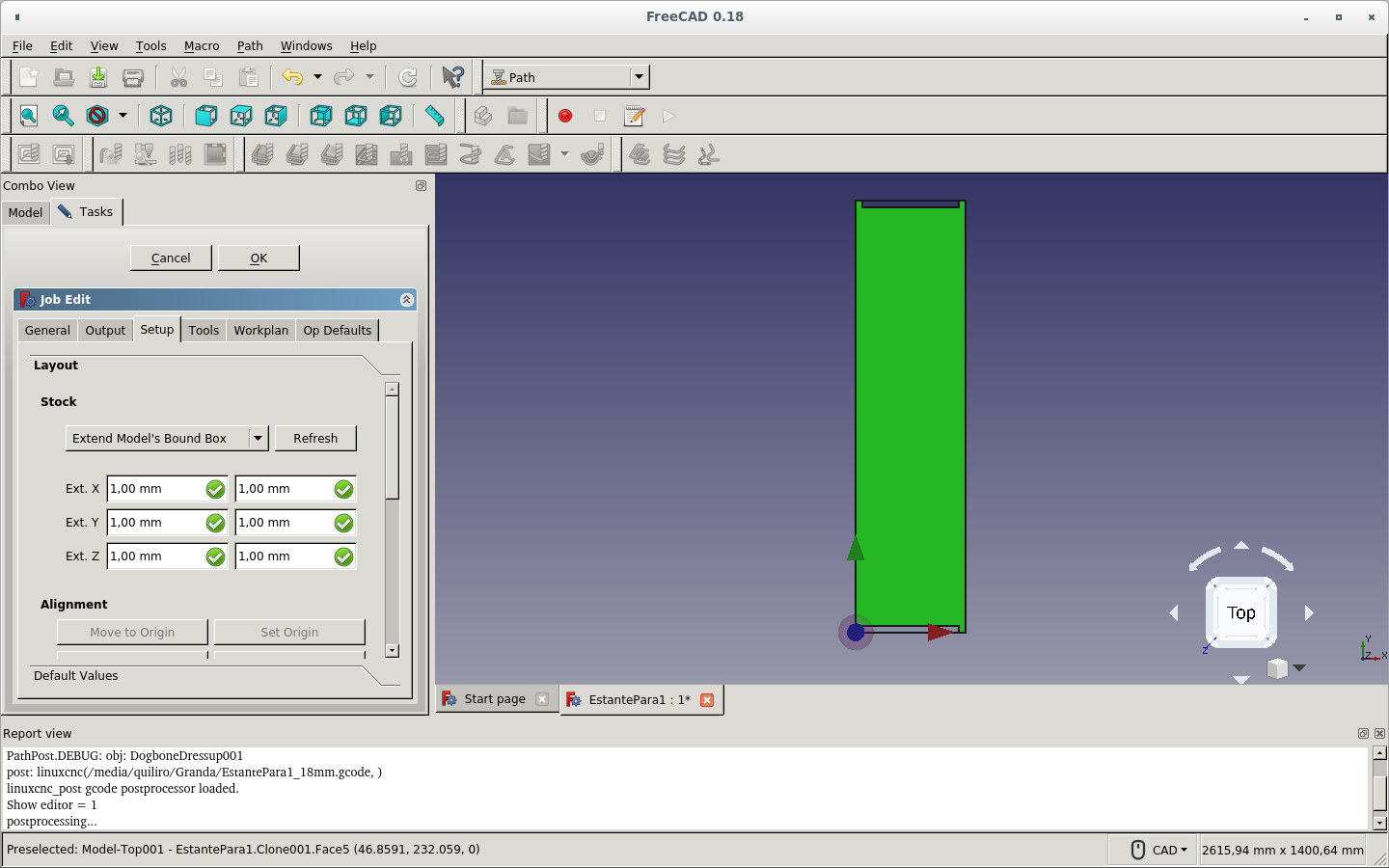
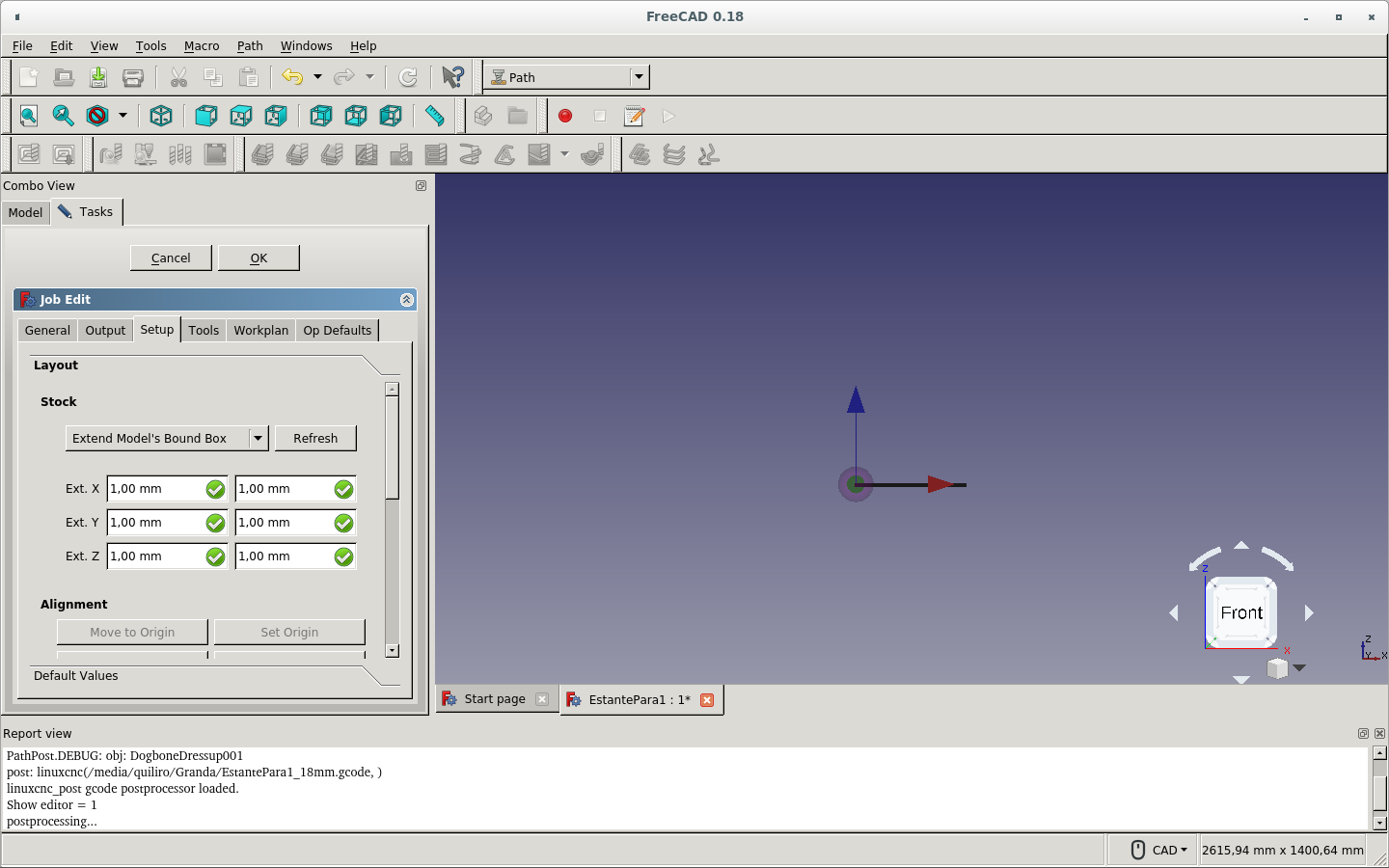
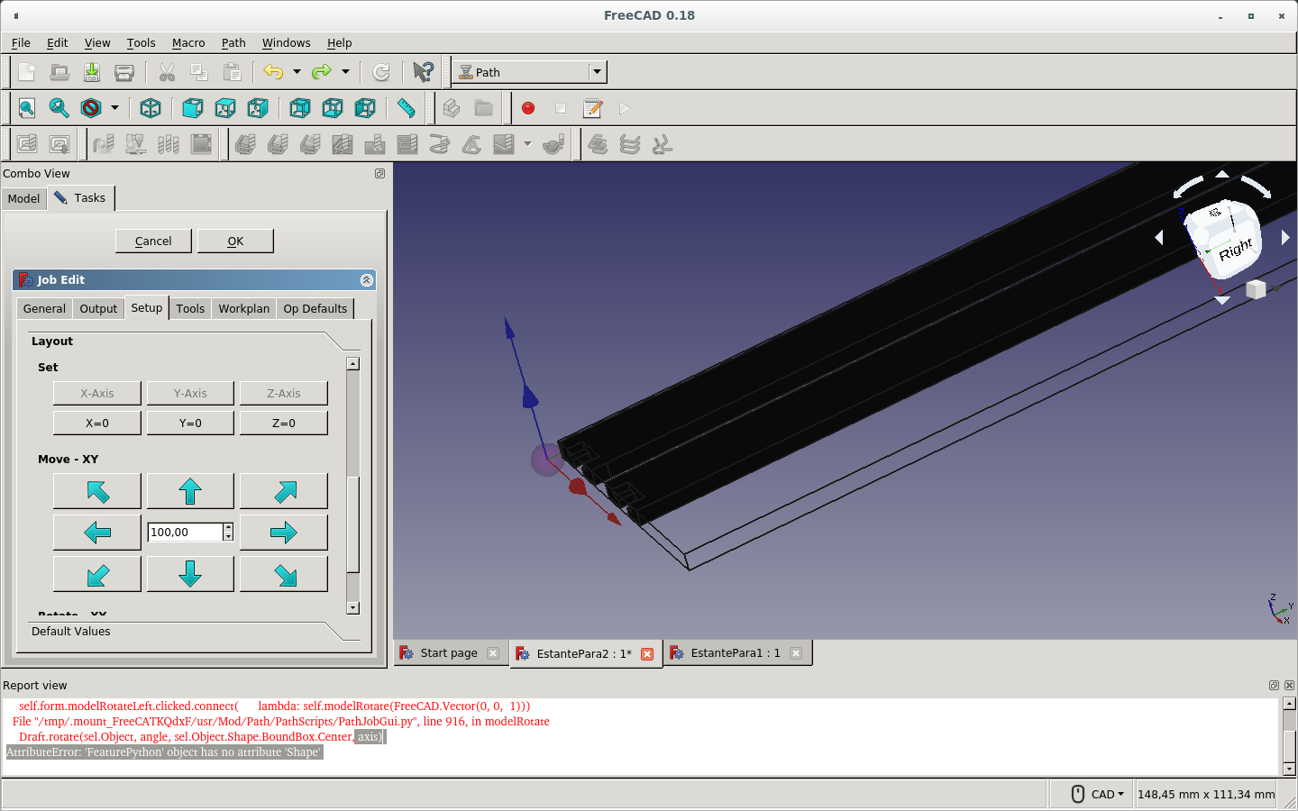
The origin is not on the corner of the stock.
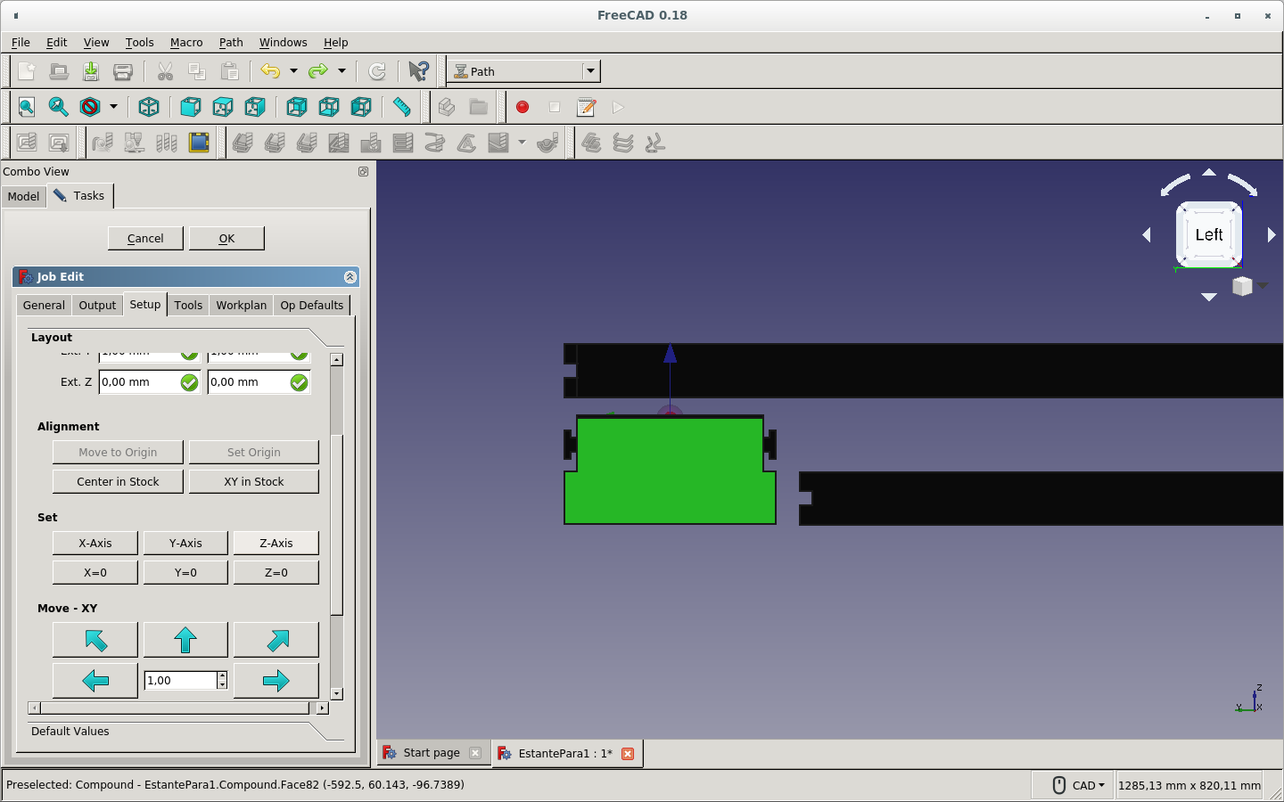
These are several tries to make the stock placement correct.
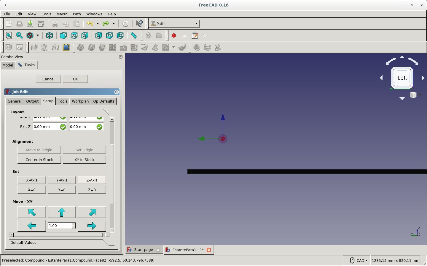

I finally could set the origin axes where the stock starts with the provided Alignment and Set options on the Layout section of the Setup tab of the Job.
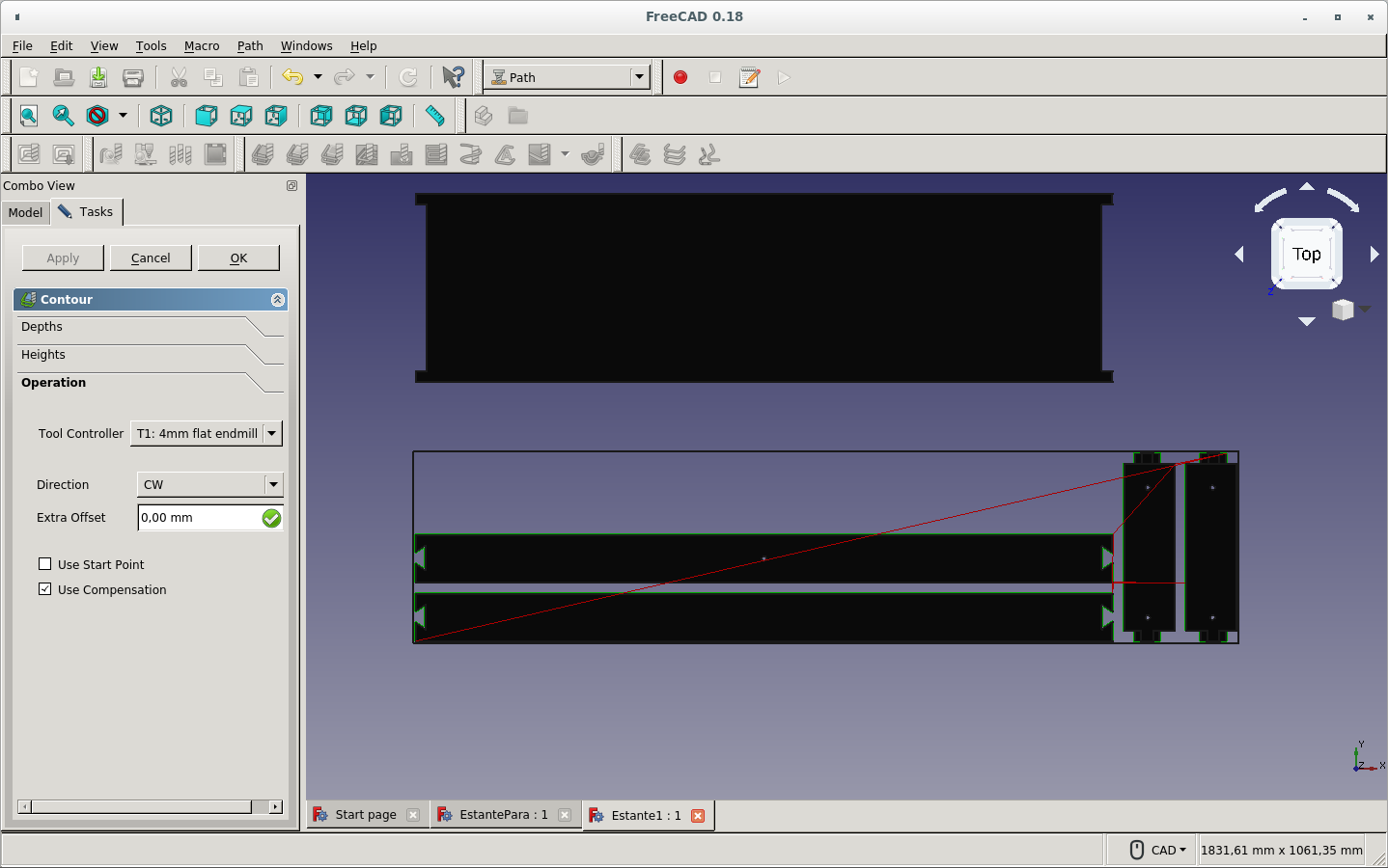
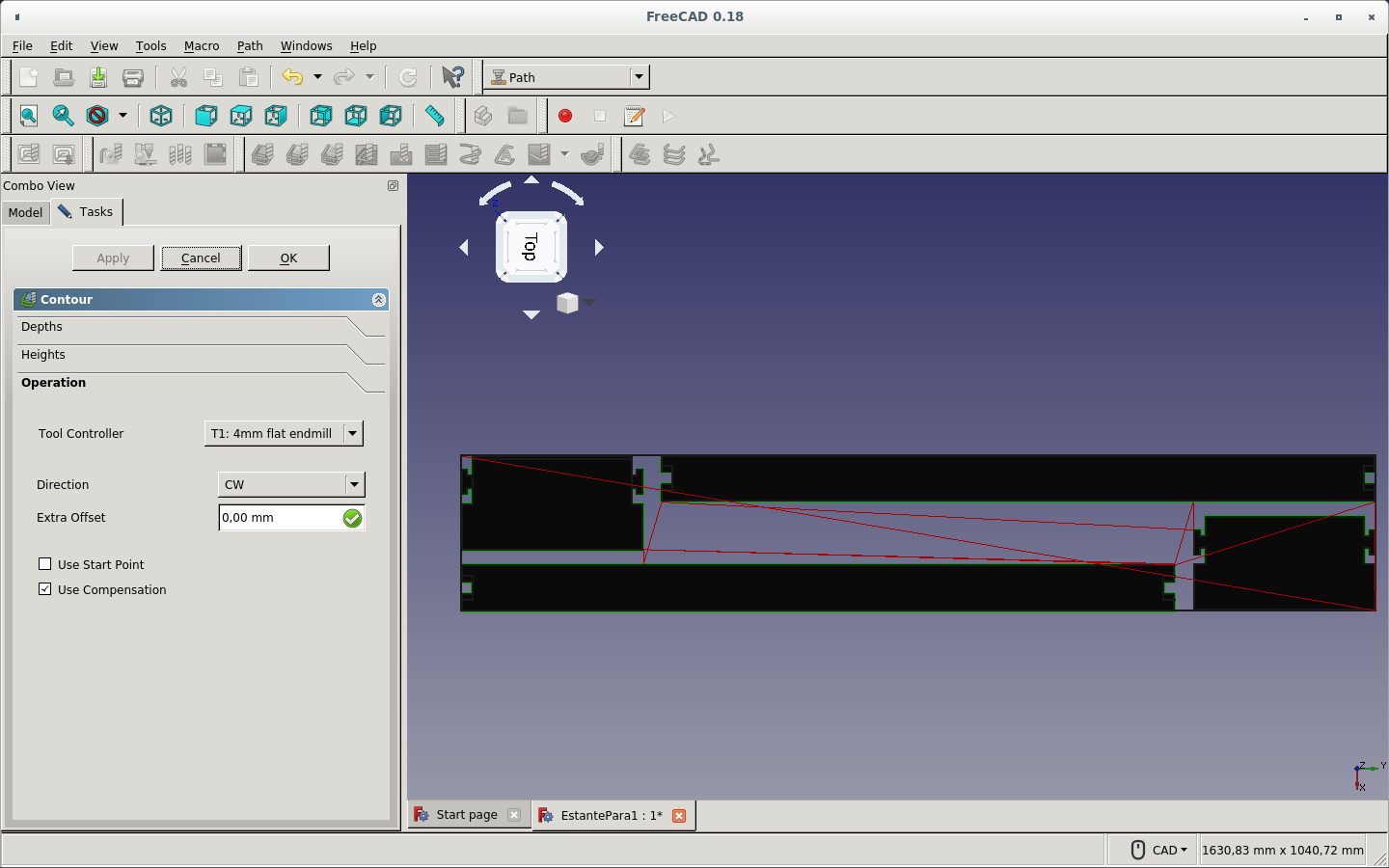
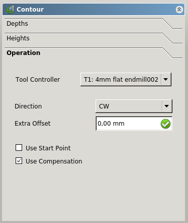
Now I click on the Contour path icon and use the default settings to cut around the pieces.
I select the notches to Create a Face Operation on those faces.
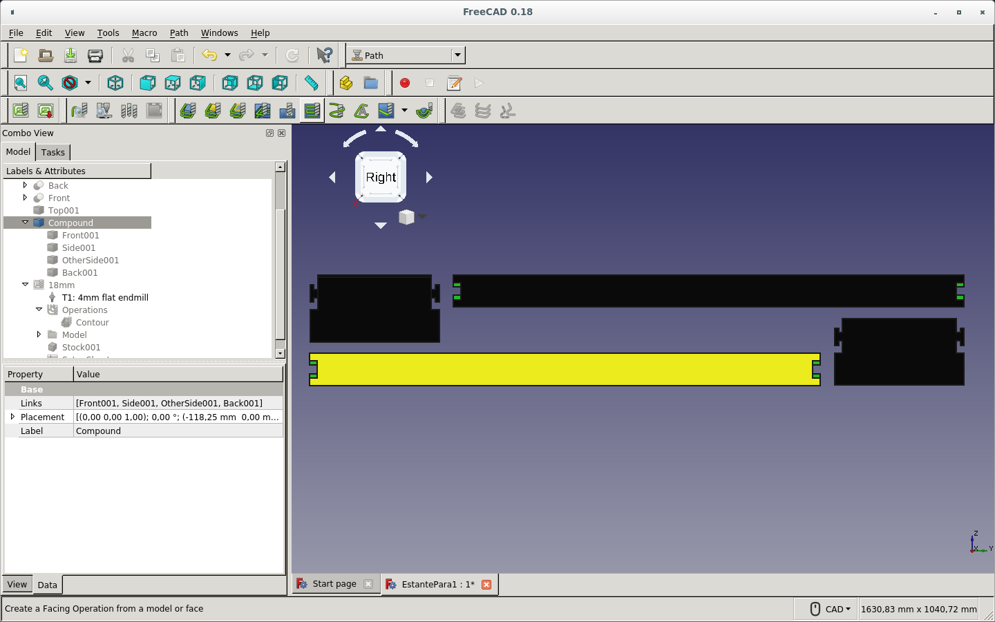
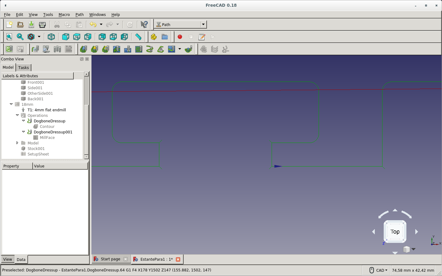
This is how the Contour path and the Face Operation path look up to now.
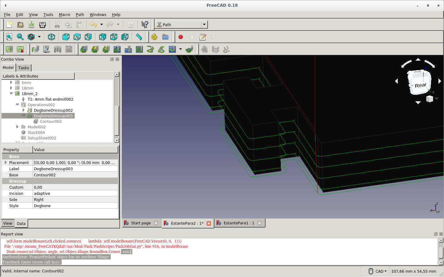
These are the Dogbone Dress-ups on the face operation paths.
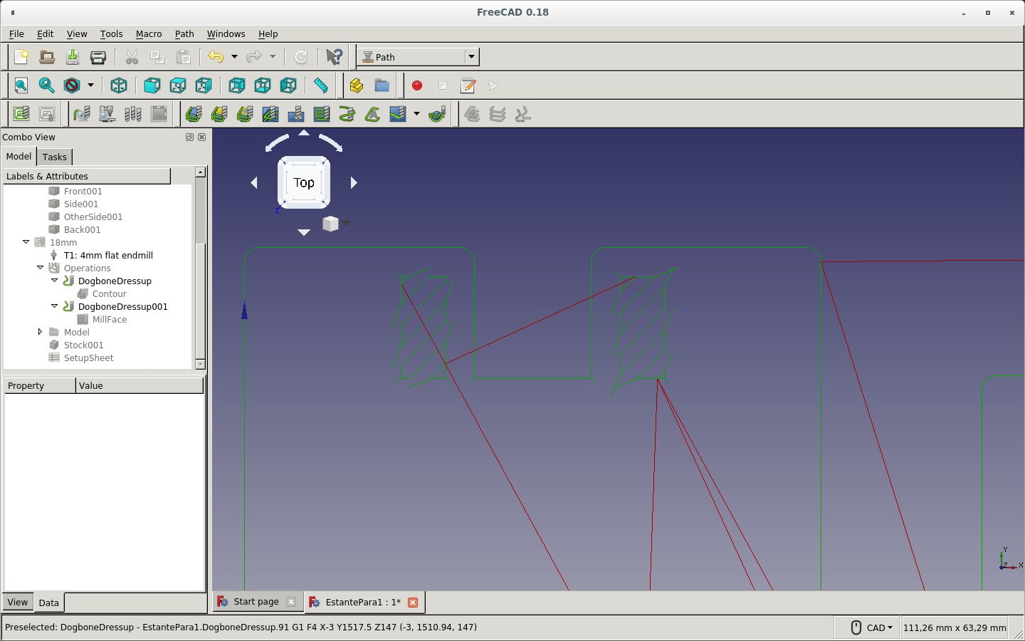
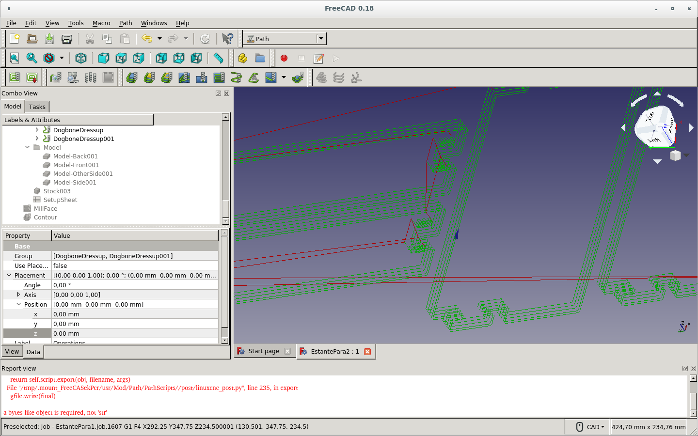
Here is the detail of the Dogbone Dress-up on the Contour path.
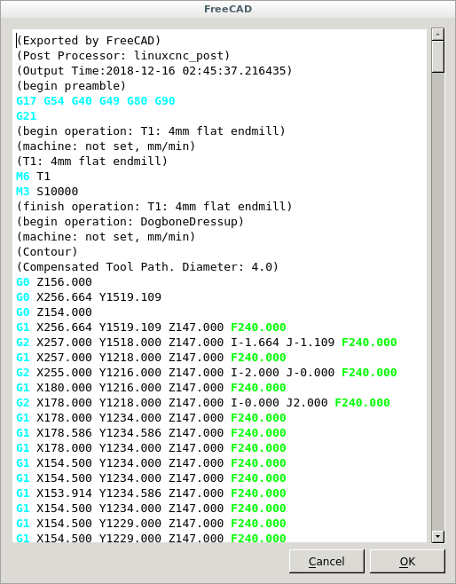
I Post-process the job and get a text which shows the Gcode. I can modify it before saving. I checked everything was well. So I clicked OK.
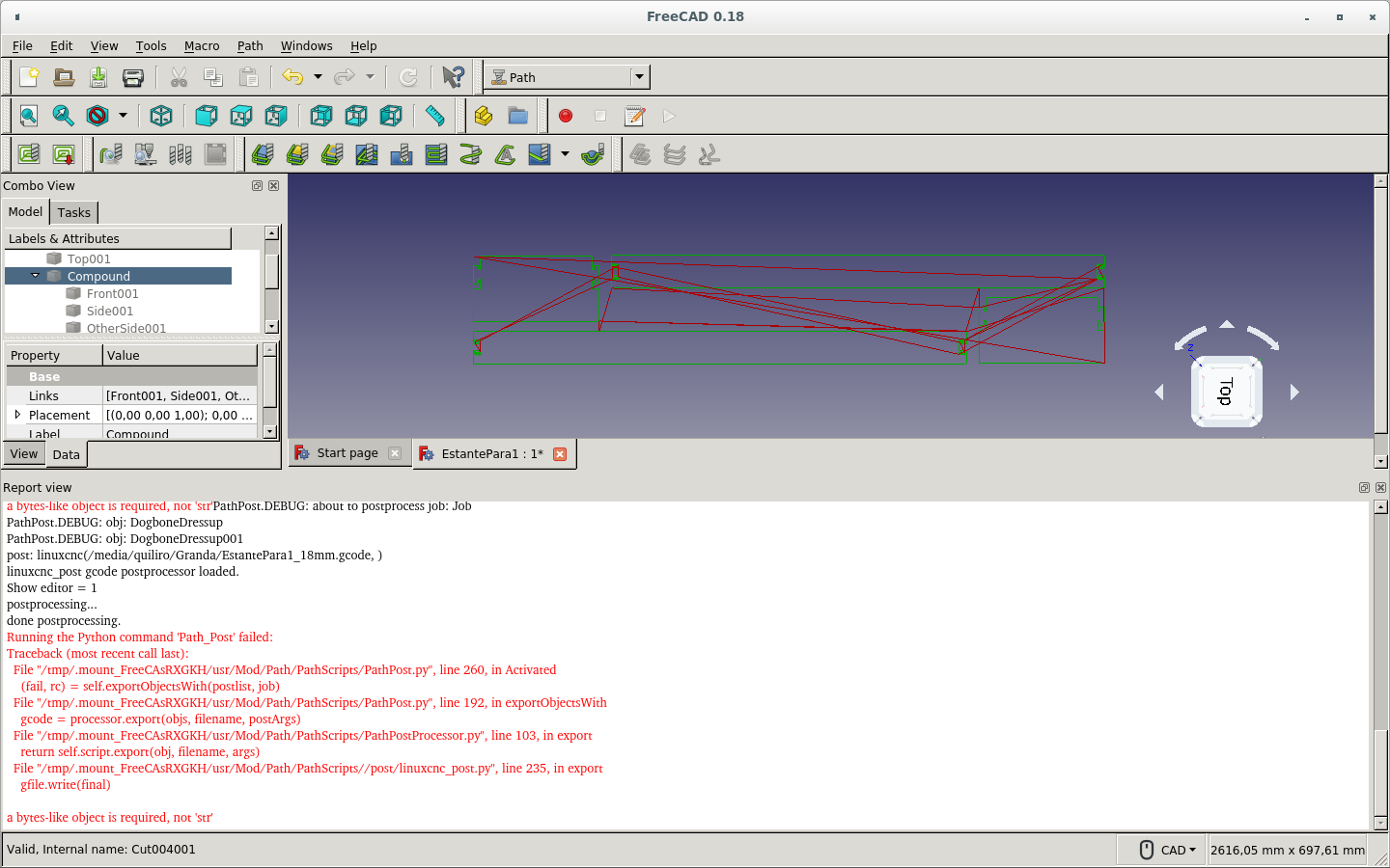
But it threw an error and saved an empty file. (It is probably because I am using a testing and not a production version of FreeCAD.) So I Post-process again and copy-paste the text on the empty file before Canceling.
Now I create a new job for the 5mm top board that has only a Contour path. (I missed adding the Dogbone dress-up.)

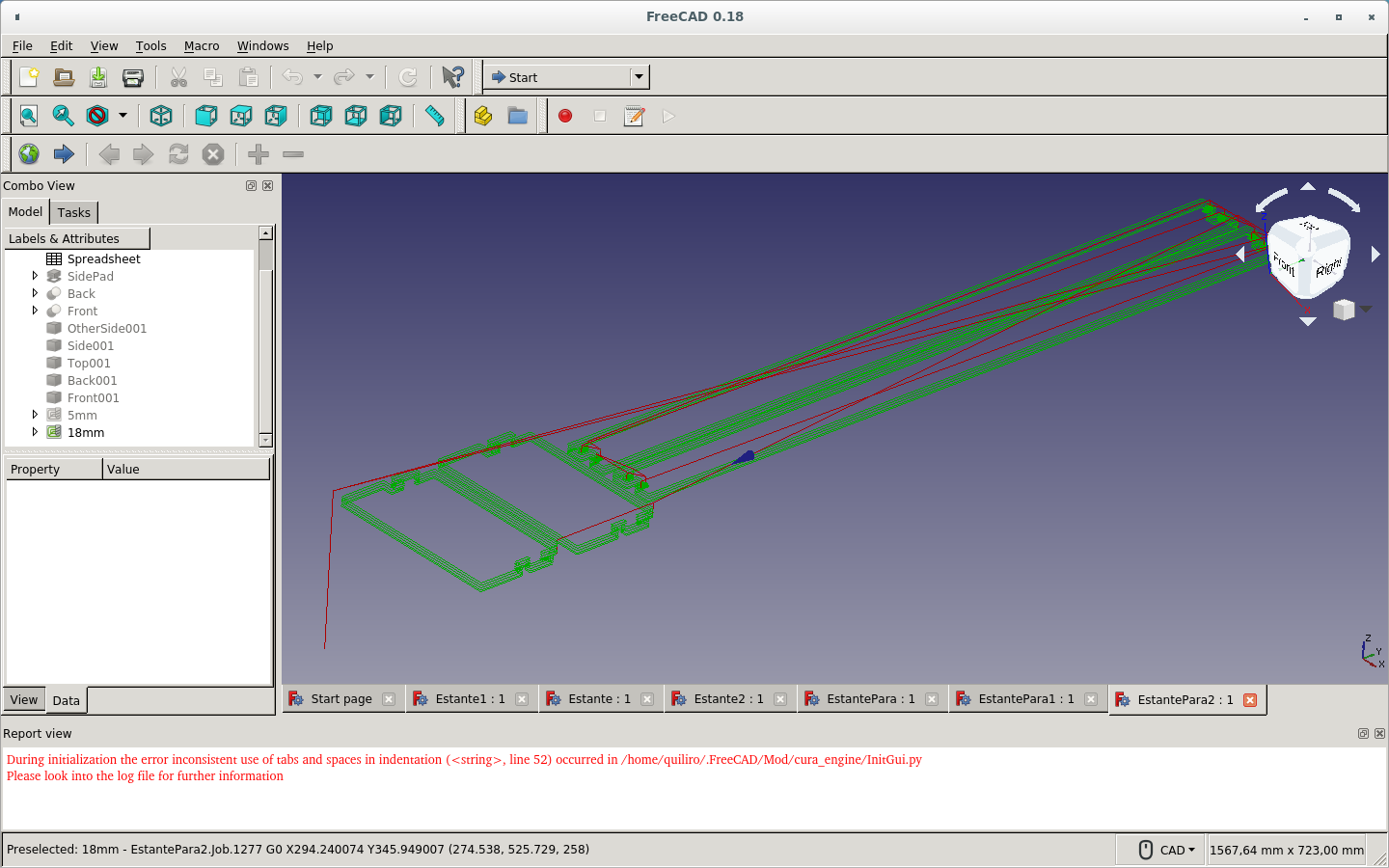
On the 18 mm paths the boards were in fact parallel. But they were on different planes. So I did the process again. Below are the pictures of the repeated process. As you can see, the boards are not aligned with X-Y plane. The axes are not on the corner of the work to be done.
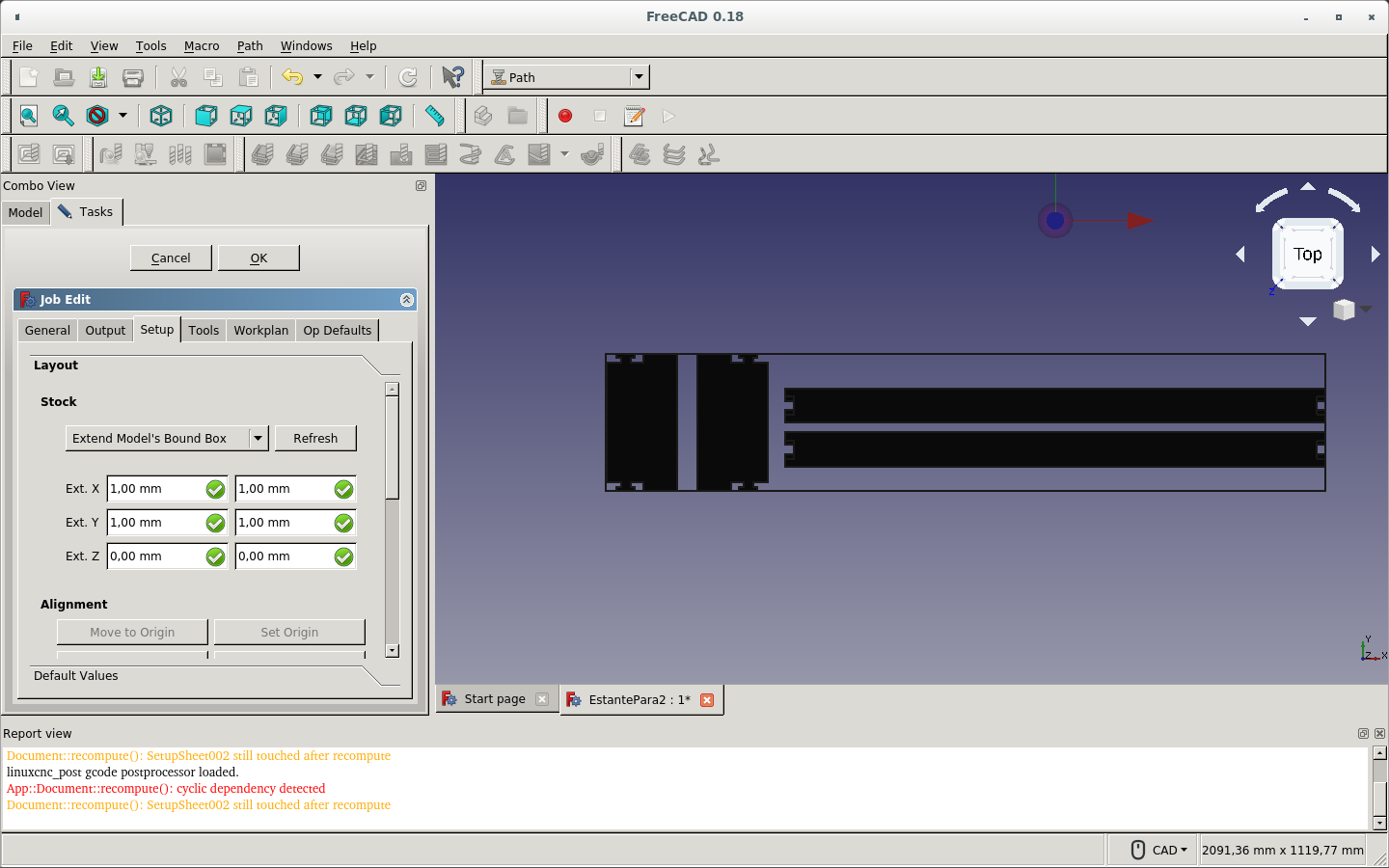
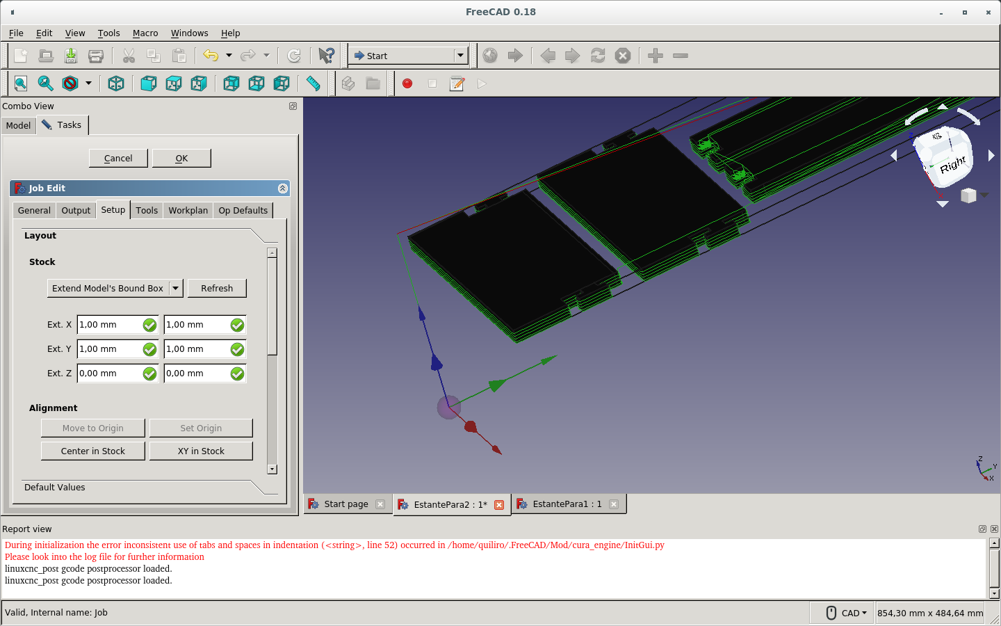
So now I had it aligned by way of the SetUp tab on job editing.

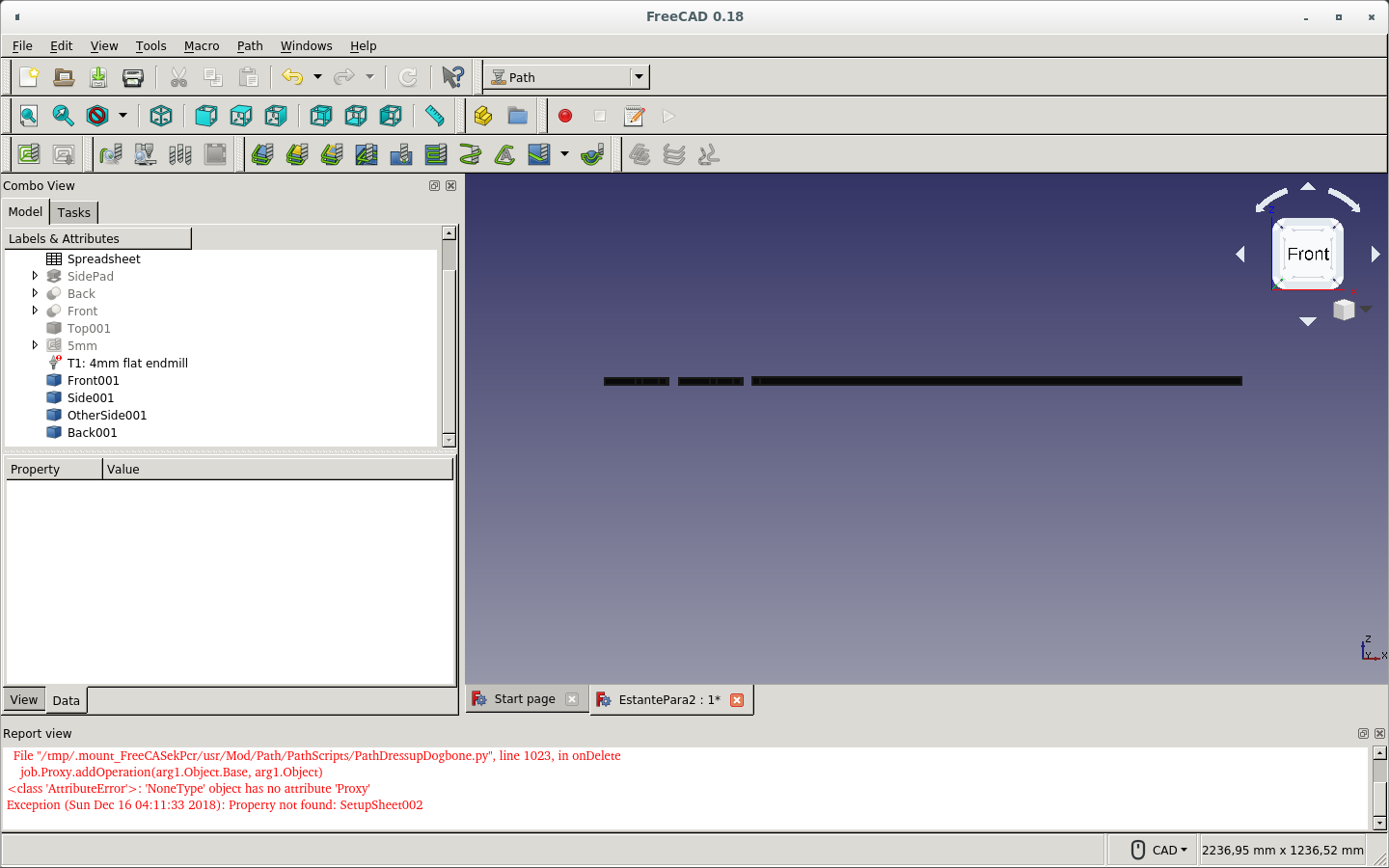

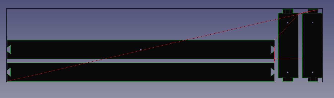
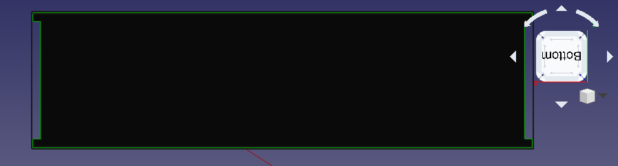
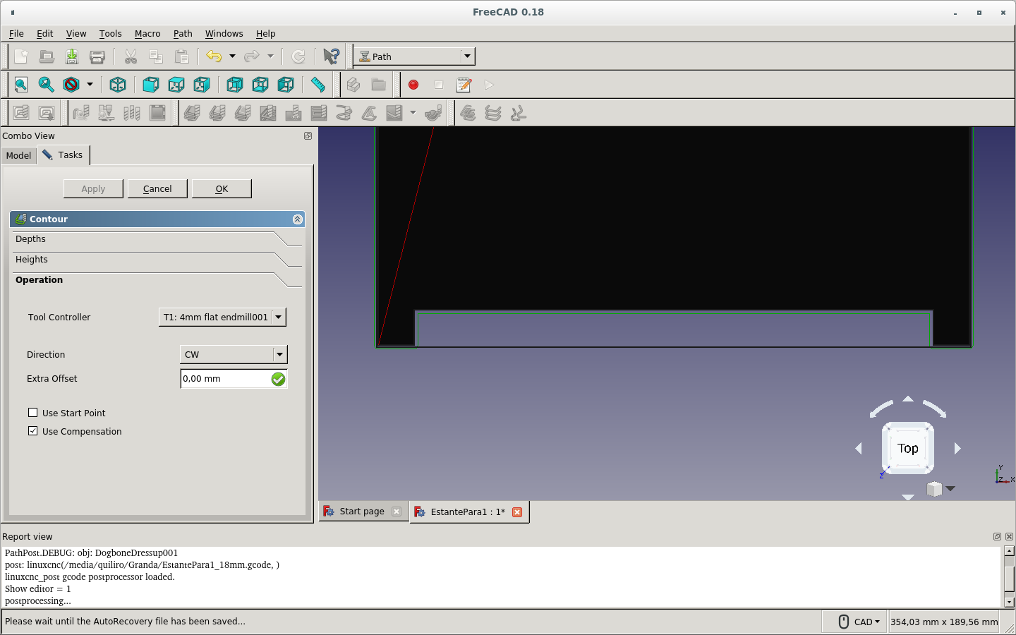
The image below shows that the path is upside-down since the red line should go from the top of the endmill starting position to the first milling point of the stock material. Rather than that, the vertical red line goes from the bottom to the lower point of the stock material below where the milling should start.
By editing the job through the SetUp tab, I could have changed the position of the cuts.
But I did not know about this option. So I made a new path job.
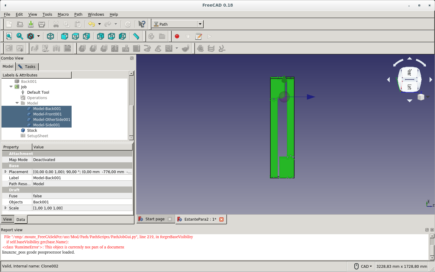
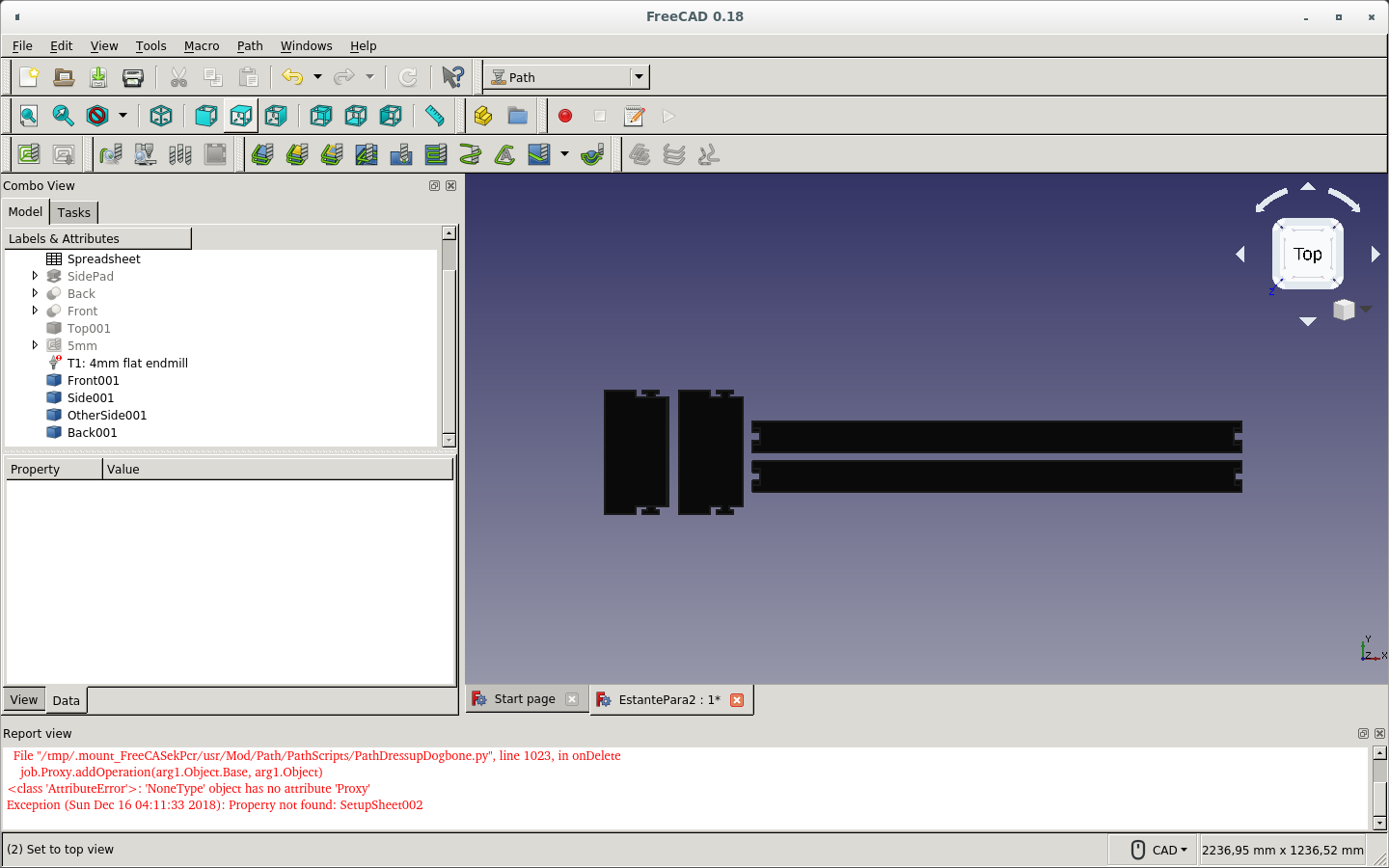
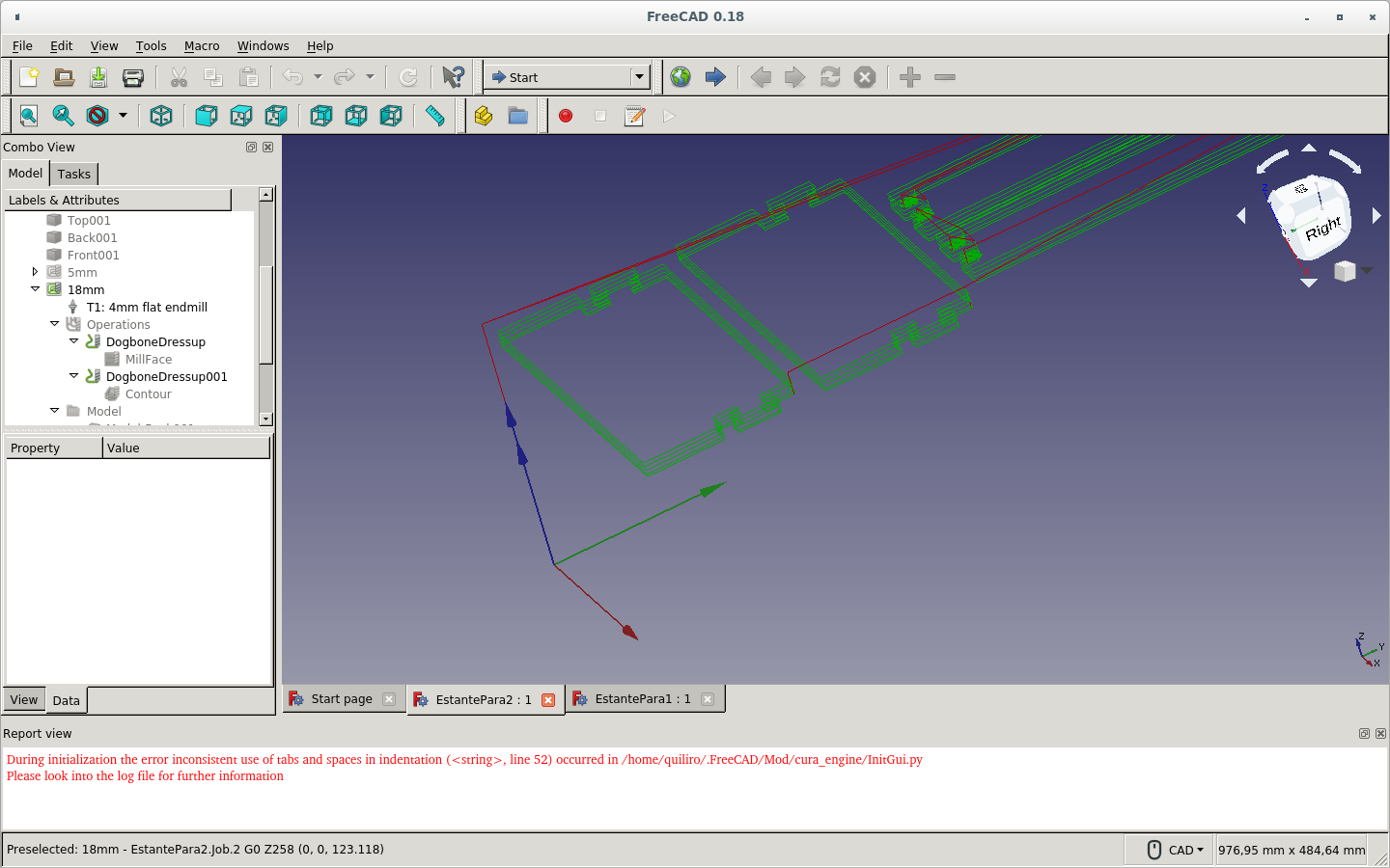
I chose the pieces on the original placement. So I changed to the piece copies that were placed on the same plane.
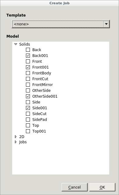
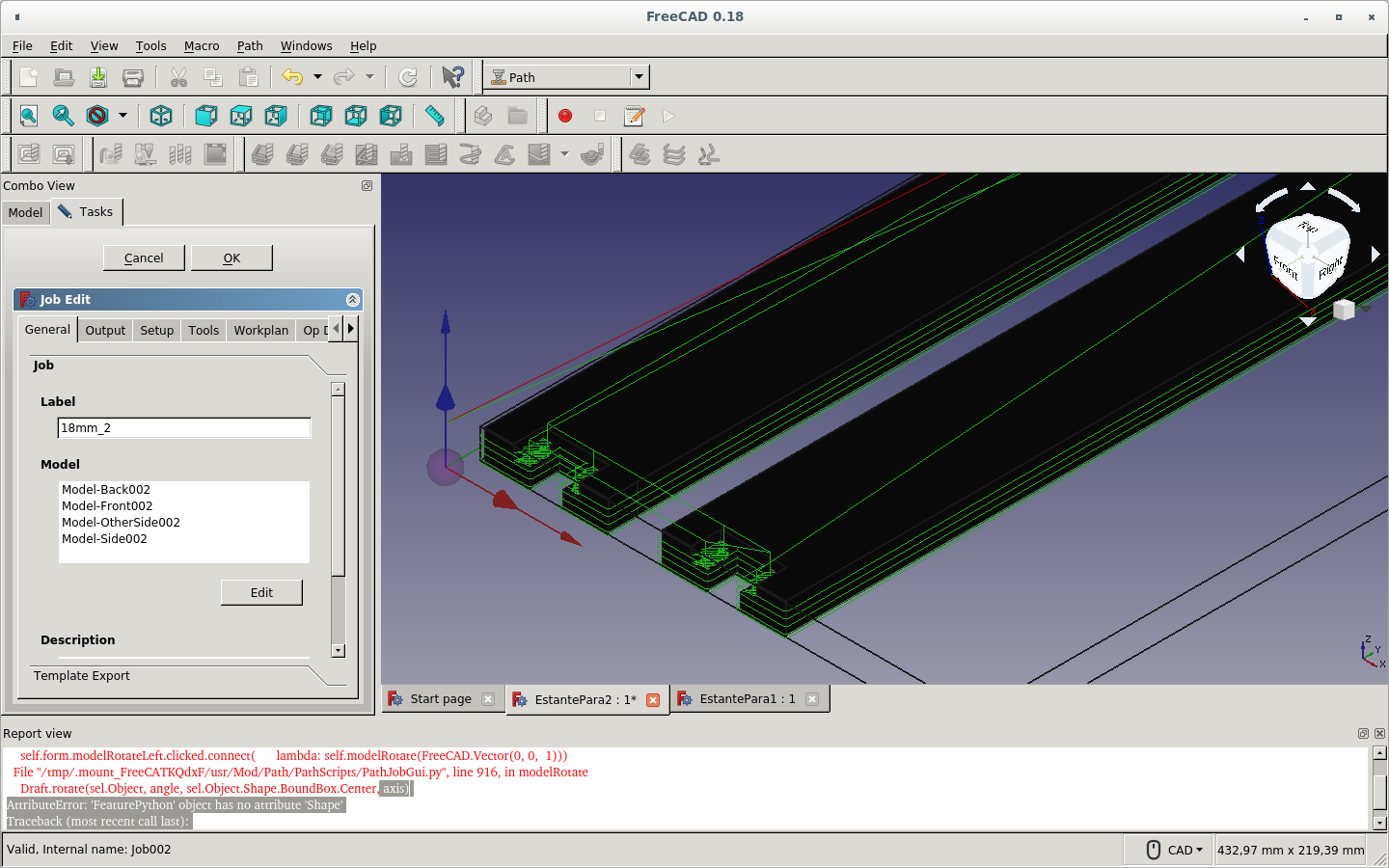
As you can see, I now oriented the pieces with X-Y axes (red and green).
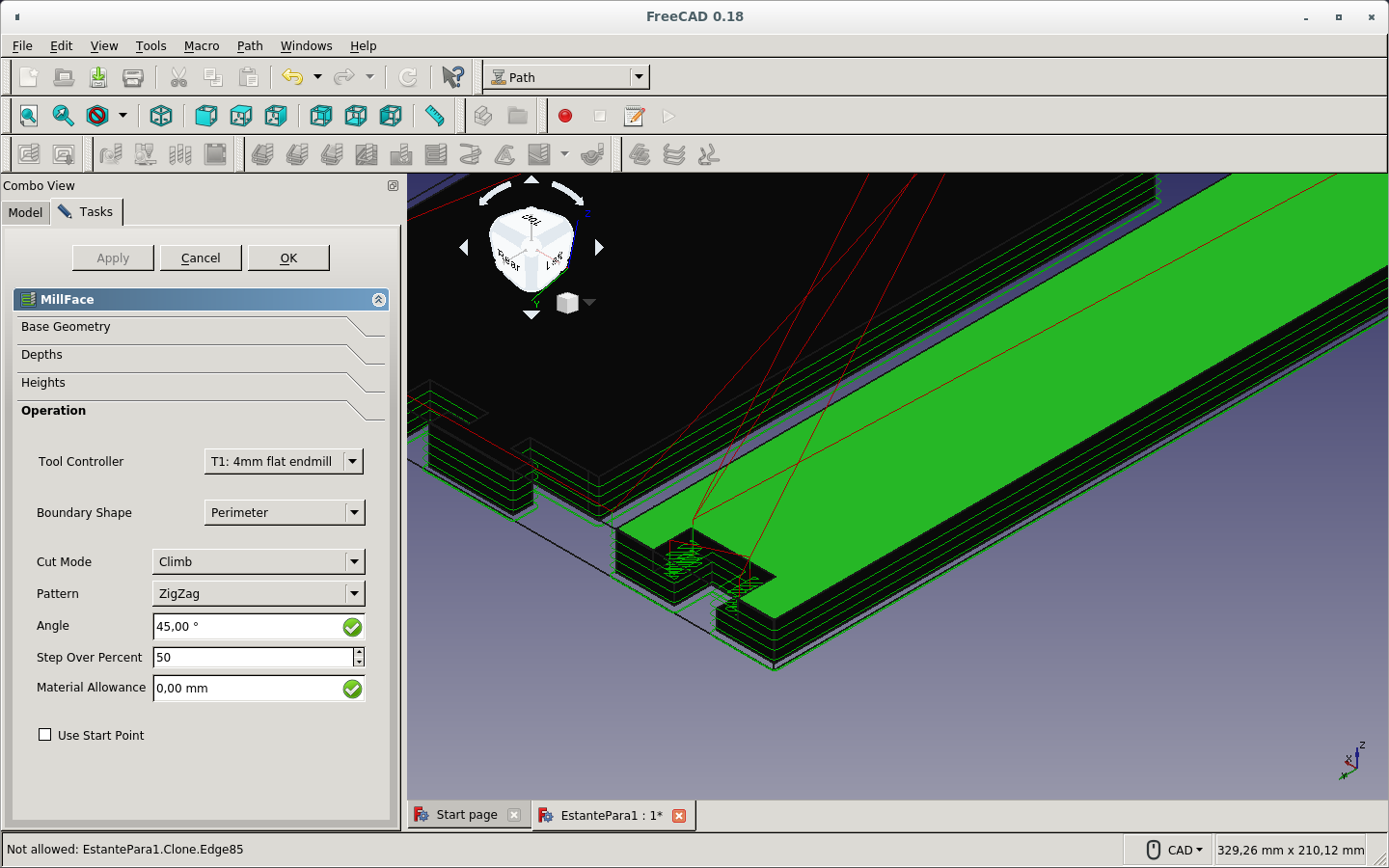
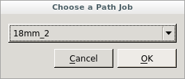
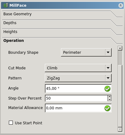
I created an new Mill Face Operation and assigned it to a new 18mm job. (I previously renamed it to 18mm_2.)
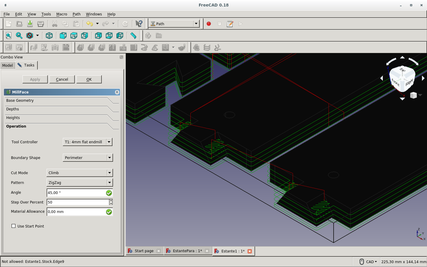
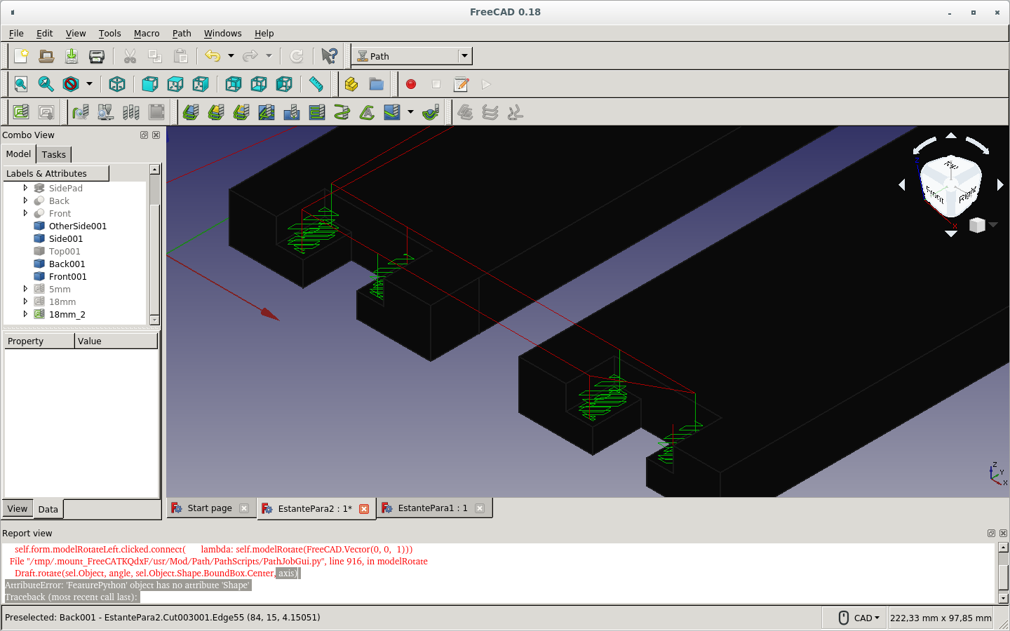
Then I set the way the operation should be performed.
This was the result.
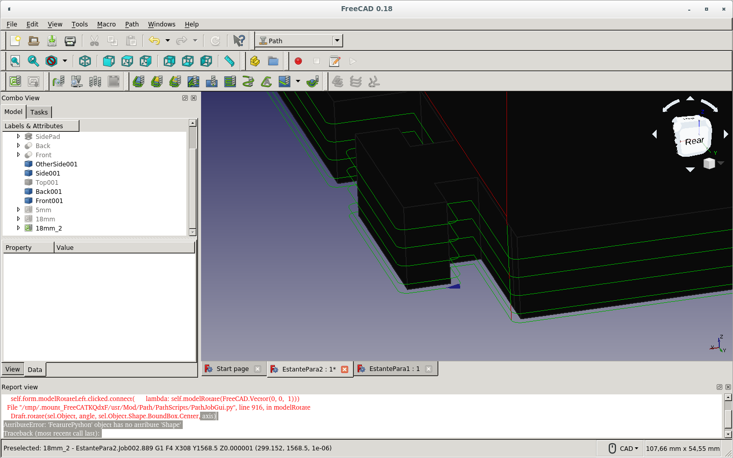
After that partial cut, I could then perform the Contour Qperation in order for the lateral cuts to be made and the pieces removed.
This is the result of the Contour Operation.
And this is the result after adding the Dogbone Dressup.
Here is the job edition showing the parts involved.
I fix the board with screws to the table protection material.
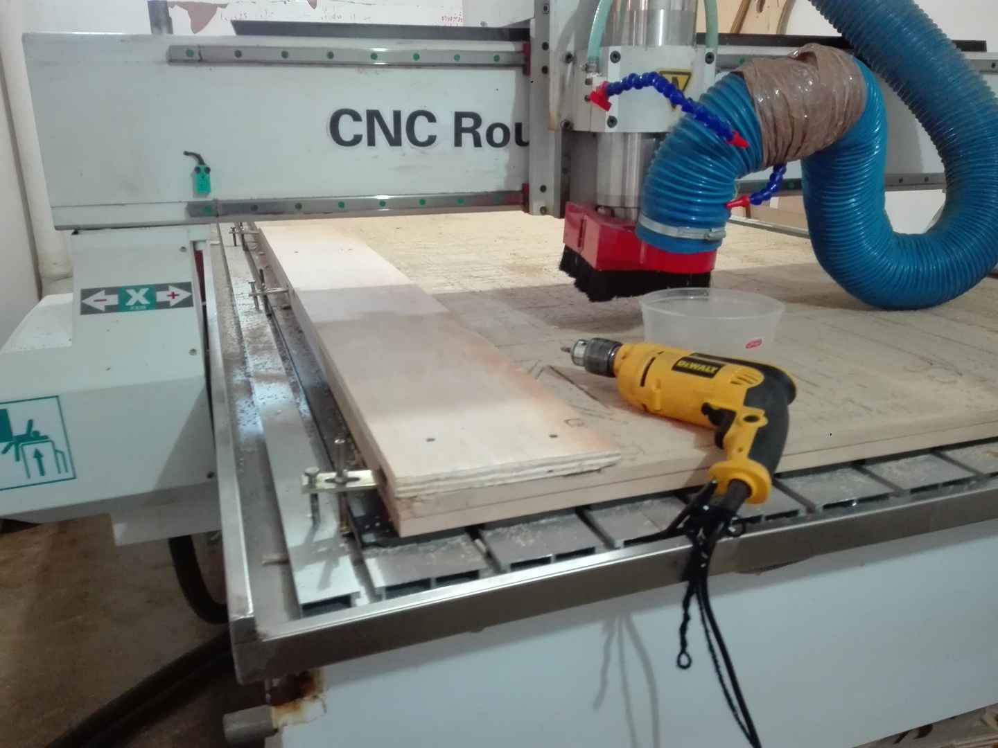
This way I fix the Z zero. (I also had fixed the X and Y zero at the corner of the stock material.)
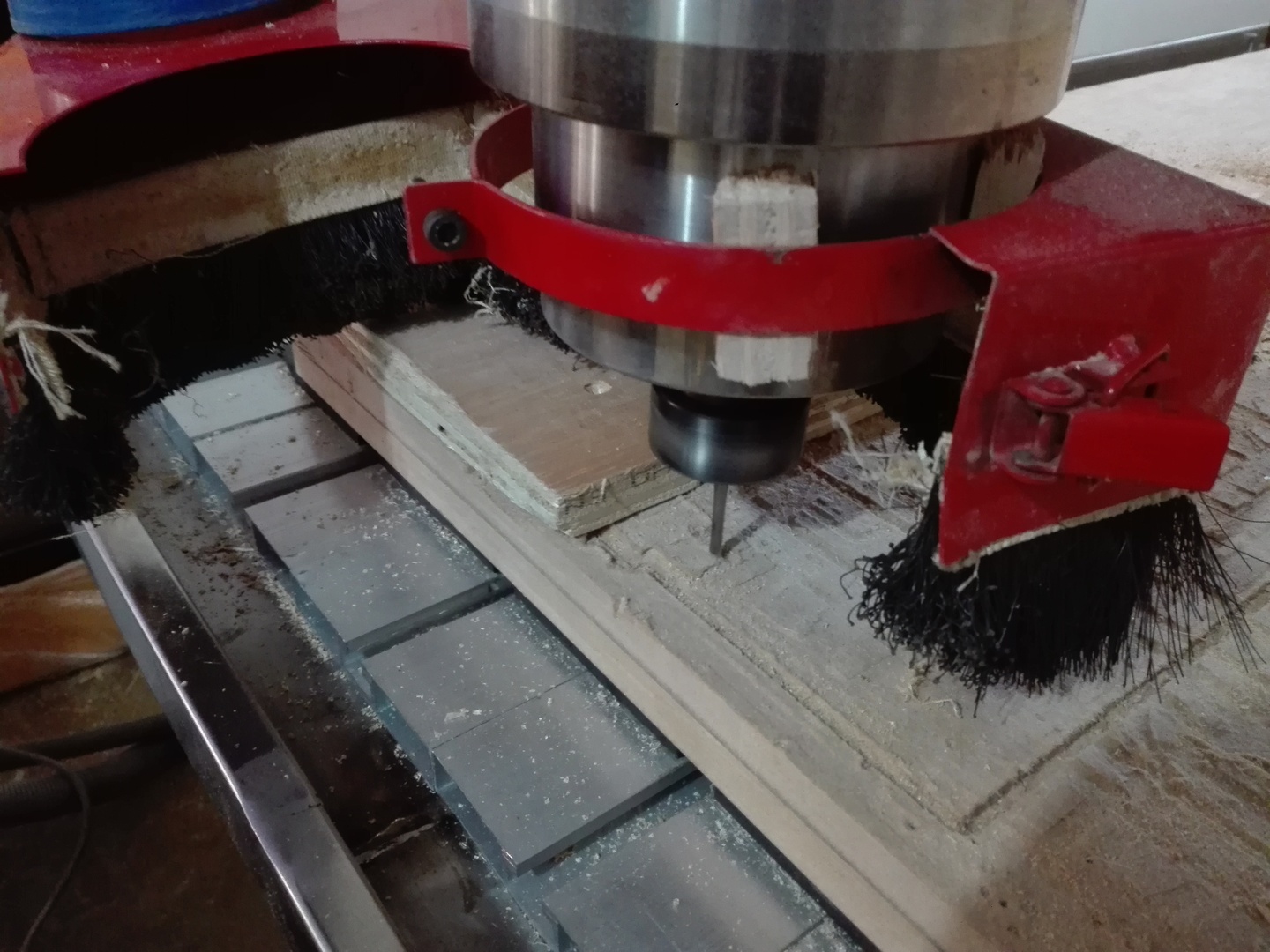
When the job starts, I notice that I am using the 6 mm endmill and the design was made for a 4 mm endmill. (Perhaps that could be parametrized too.) So I stop the work.
These are the Facing Operations done on one side of 2 pieces that are side by side.
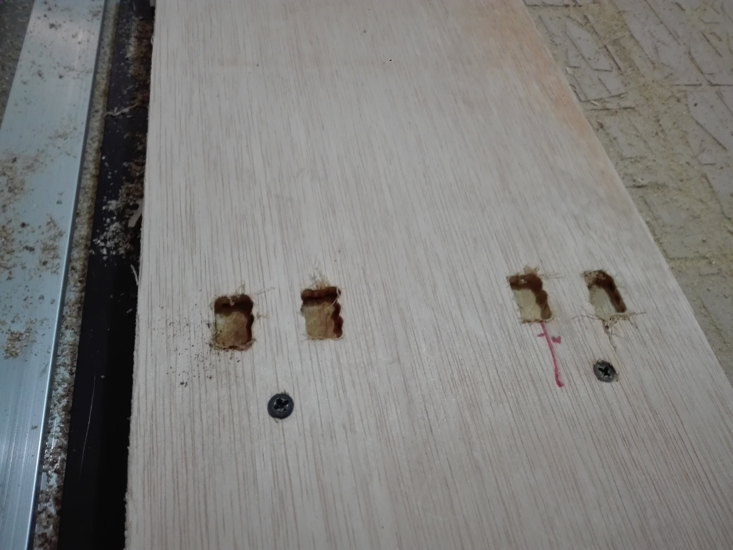
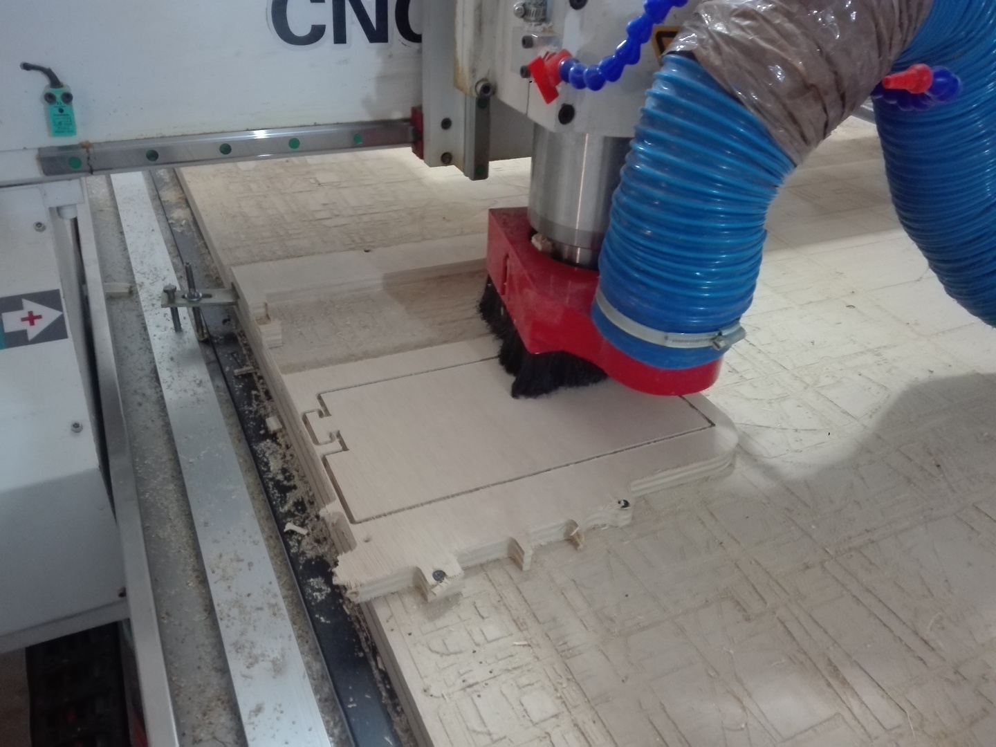
The 2 long pieces have been cut and the router is ready to cut the 2 side pieces. But the stock material is not enough. Another stock is fixed at the place where the 2 pieces will be cut.
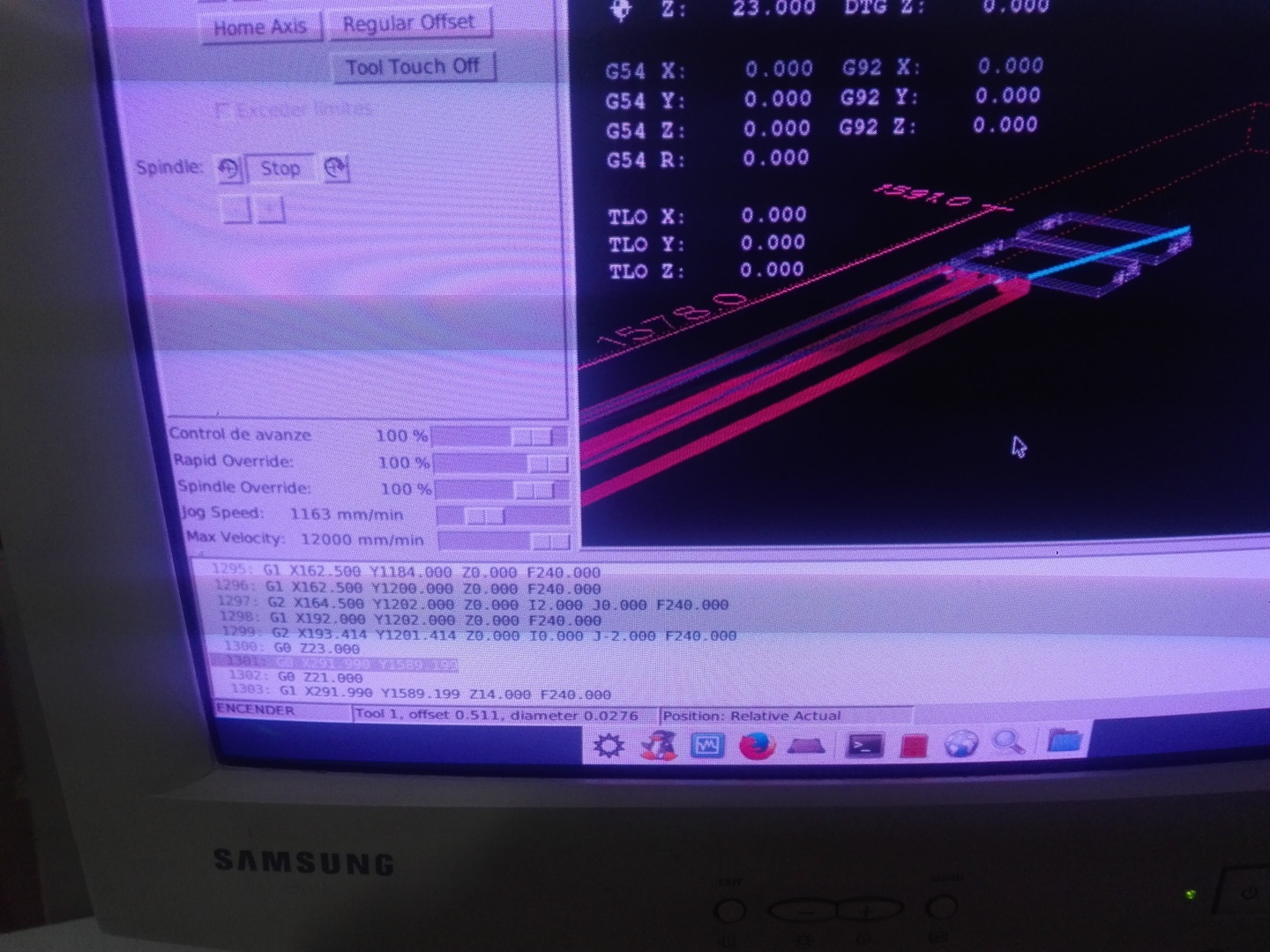
The router must be started where the Gcode starts to cut the 2 side pieces.
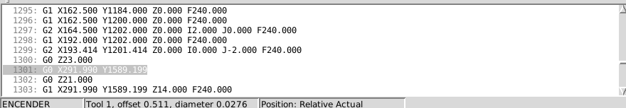
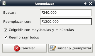
But the Gcode must be modified. The feed speed was too slow. It took 2 hours and burnt the wood. So we changed the feed speed from 240.0 to 1200.0 on all lines on both files (18 mm support pieces' gcode and 5 mm top board's gcode).
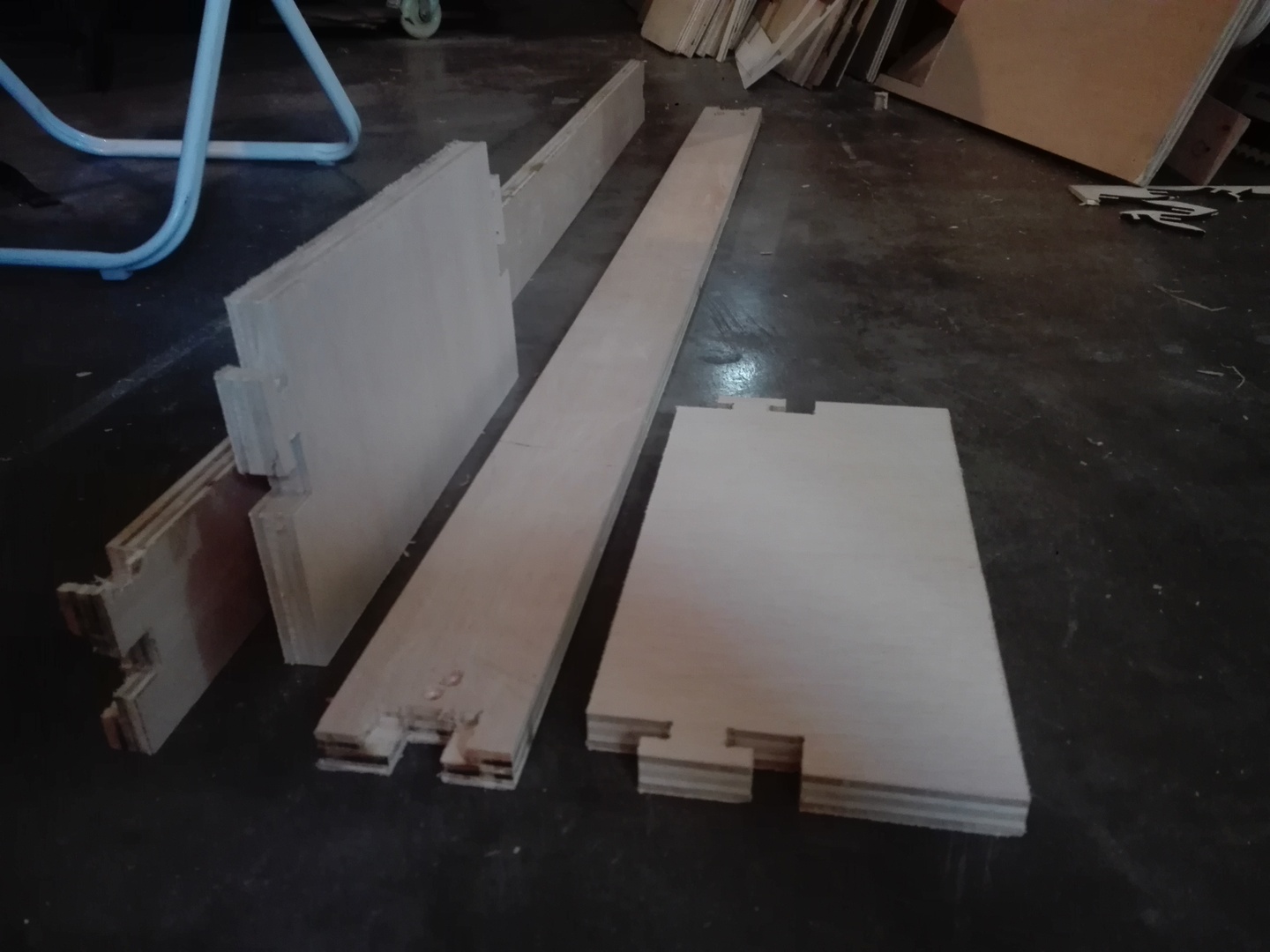
The 2 side side pieces are almost finished.
Here are the 4 finished 18 mm support pieces.
The machine settings would not allow the 2 mm from one side of the endmill to be less than 0 on X, Y or Z. So the machine would give an error and show the offending dimensions in red.
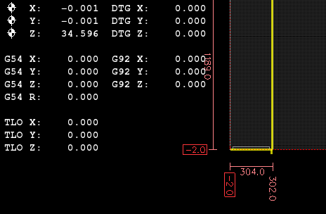
The router1325.ini configuration file is modified to accept -2 mm for MIN_LIMIT on AXIS_0 and on AXIS_1.
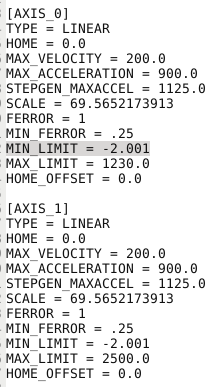
So the machine (CNC router) accepts the positioning and does not show any red numbers.
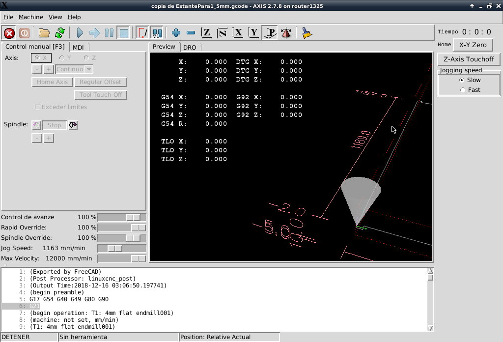
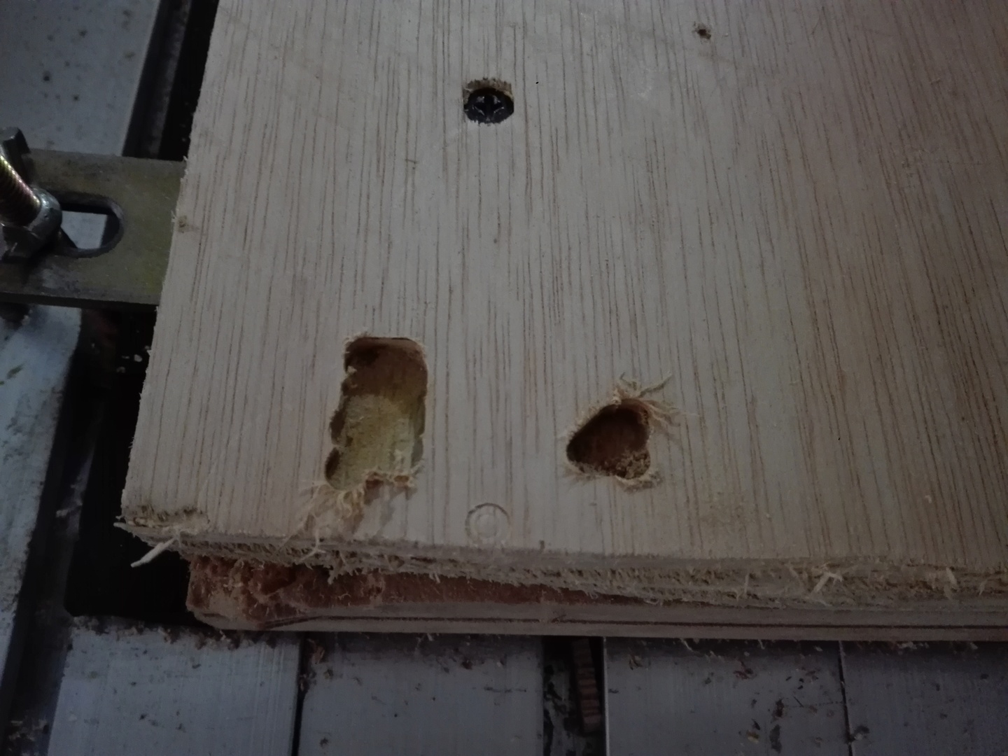
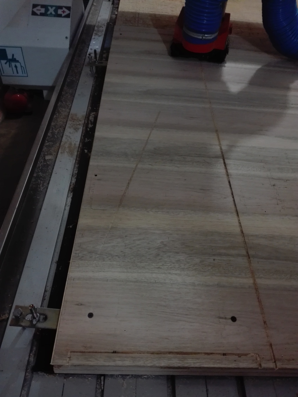
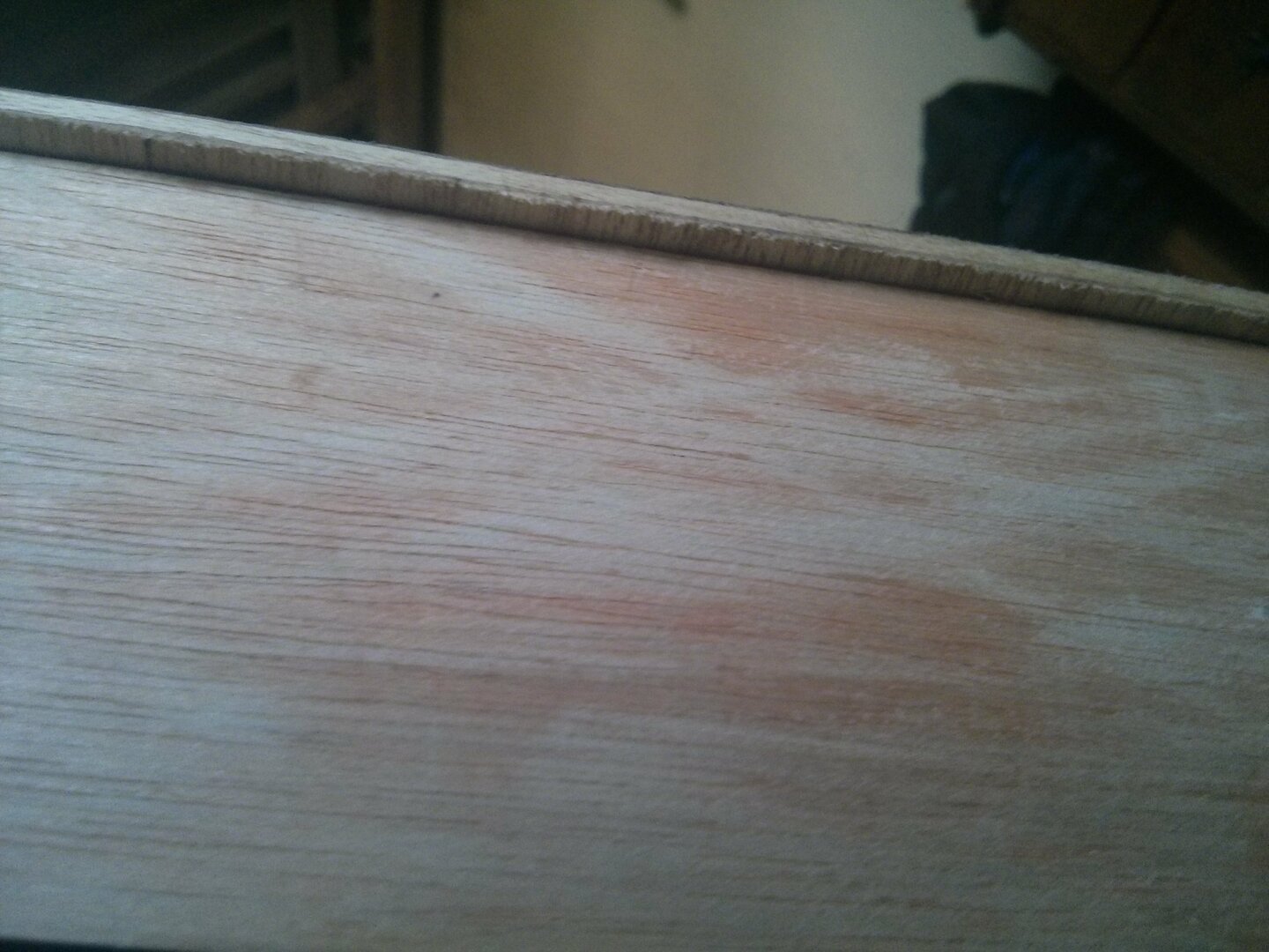
The top board is being cut. As you can see the diagonal cut, The Z axis was set as the bottom of the stock material. But the designed defined the top of the stock material as the Z zero. So the endmill passed cutting where it should have passed clear of the stock while it was going to the starting location for its Contour Operation.
I did not include a Dogbone dressup for this path.
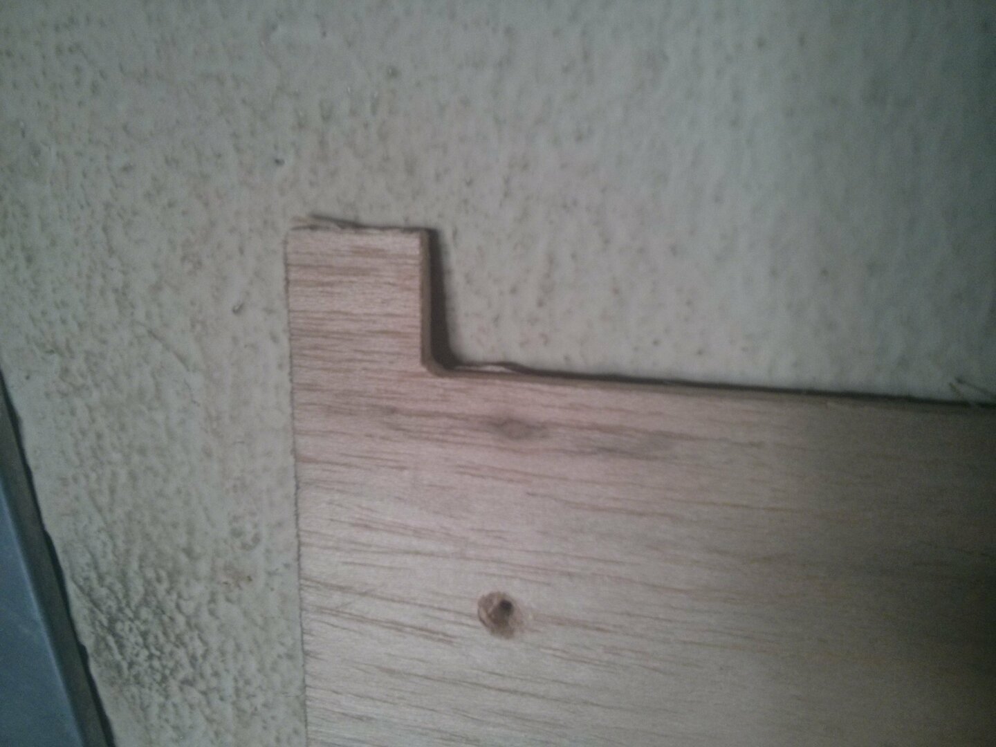
So I had to use the saw.
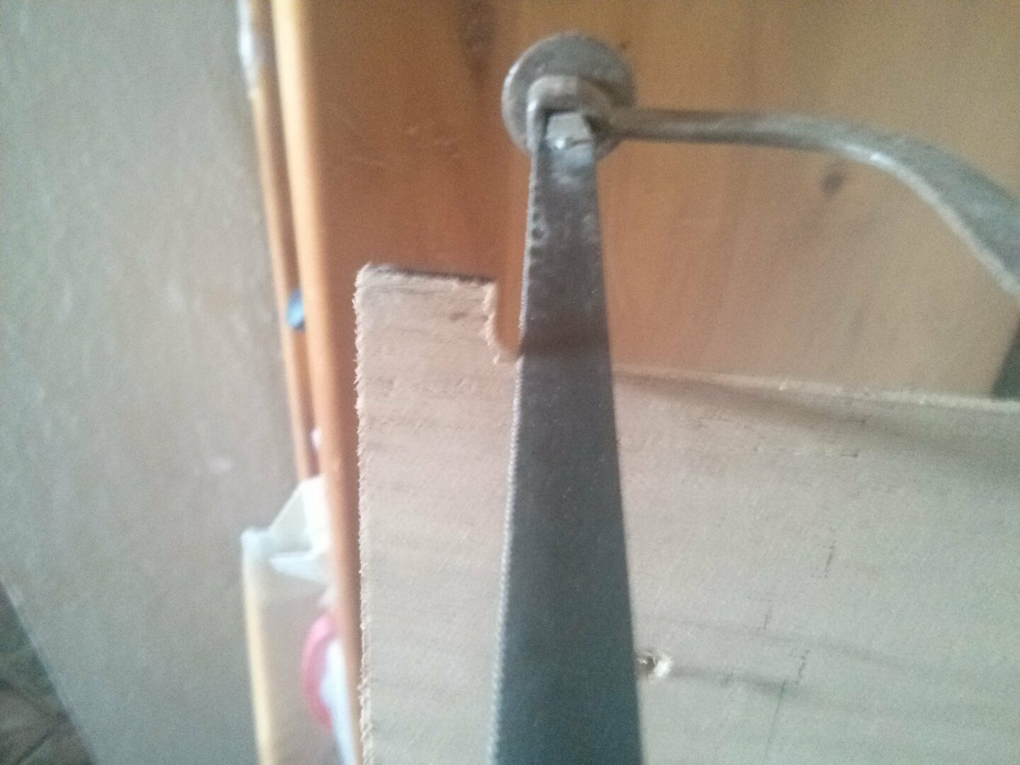
It worked well. I have a square corner now.
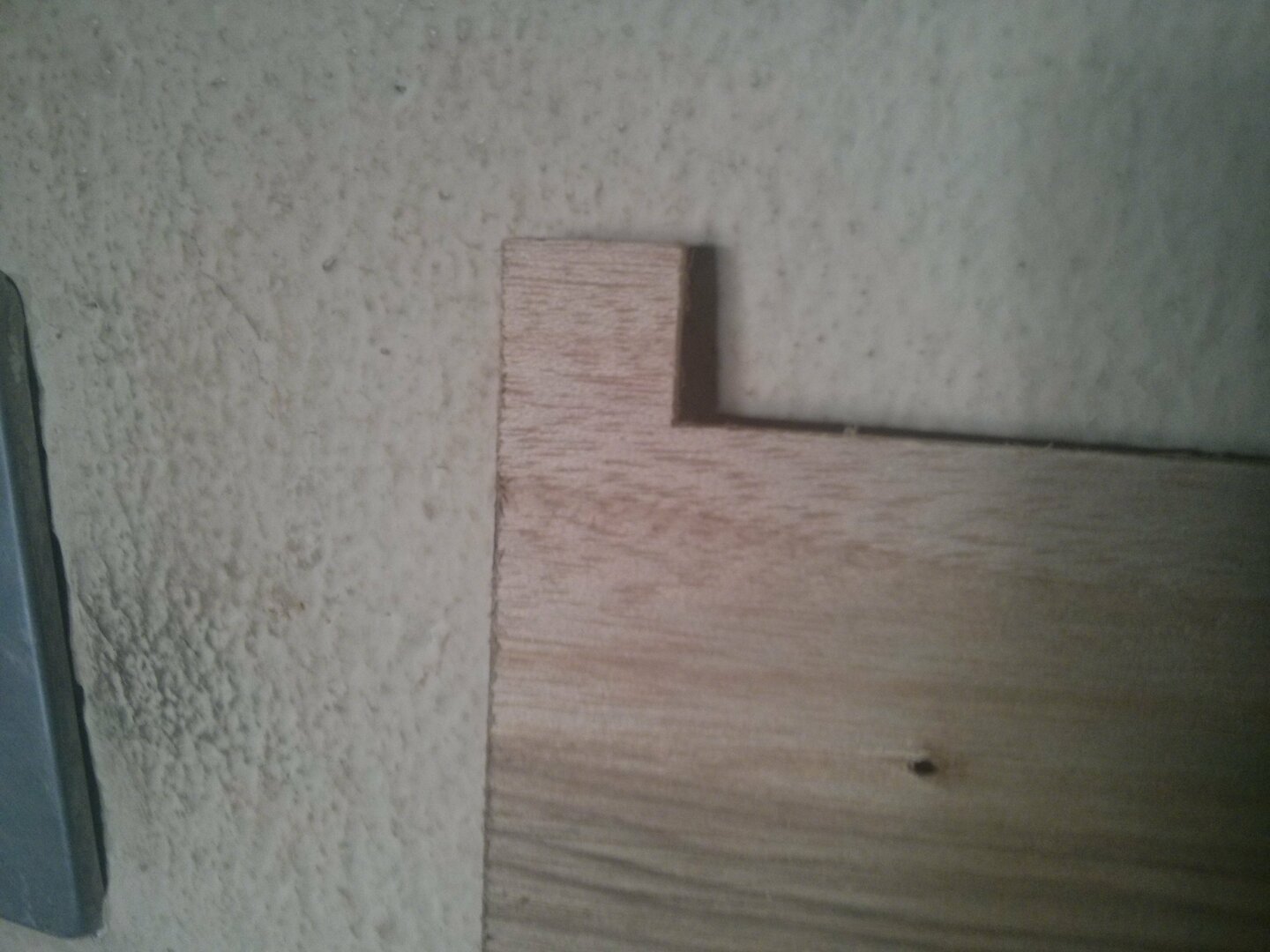
The top board goes straight. But the the back support is curved. The top board did not have a notch for the front or back supports as did the side boards.
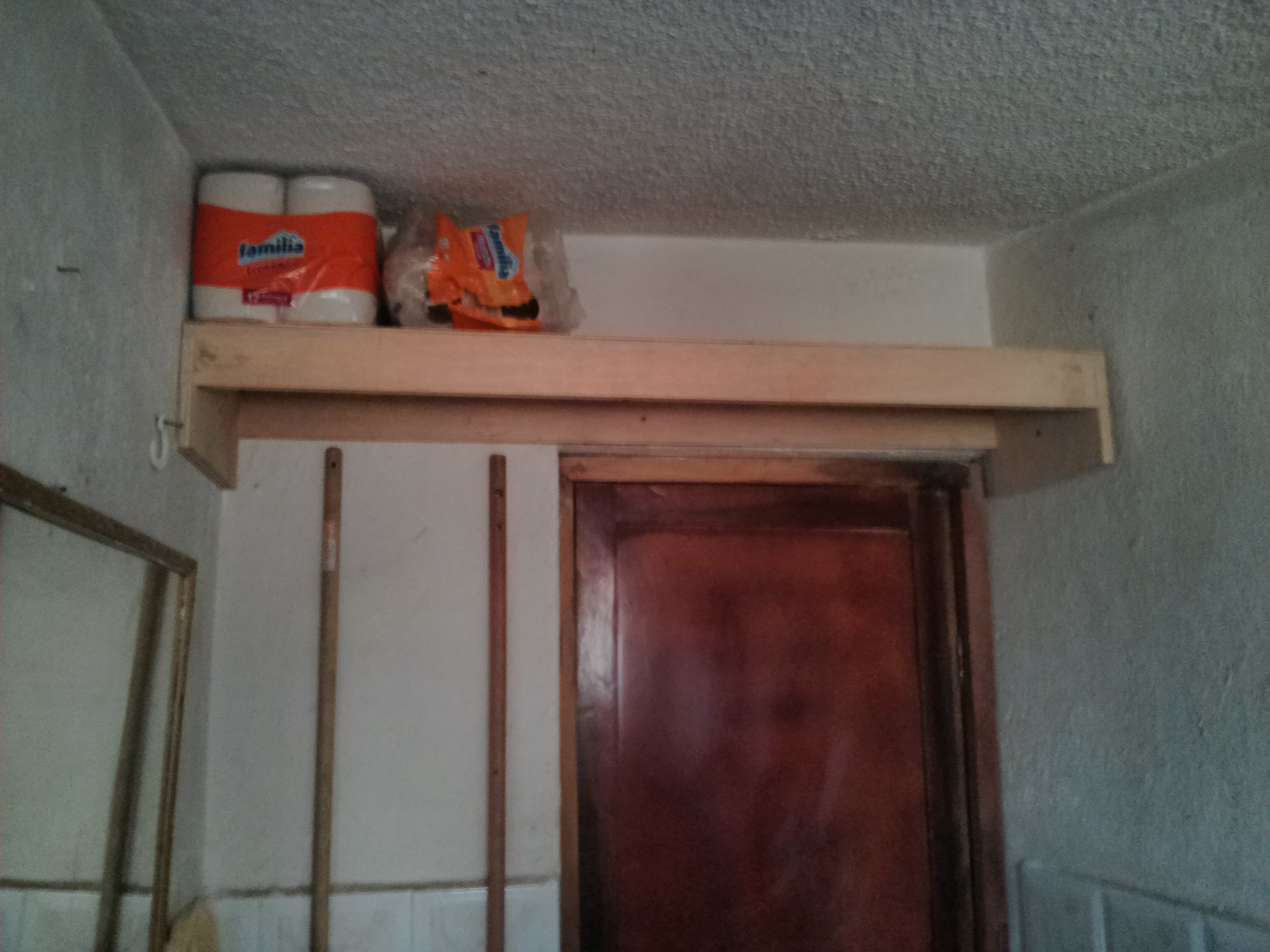
But this was solved with a screw on the back board fixing it to the wall. It also gives the structure better stability.
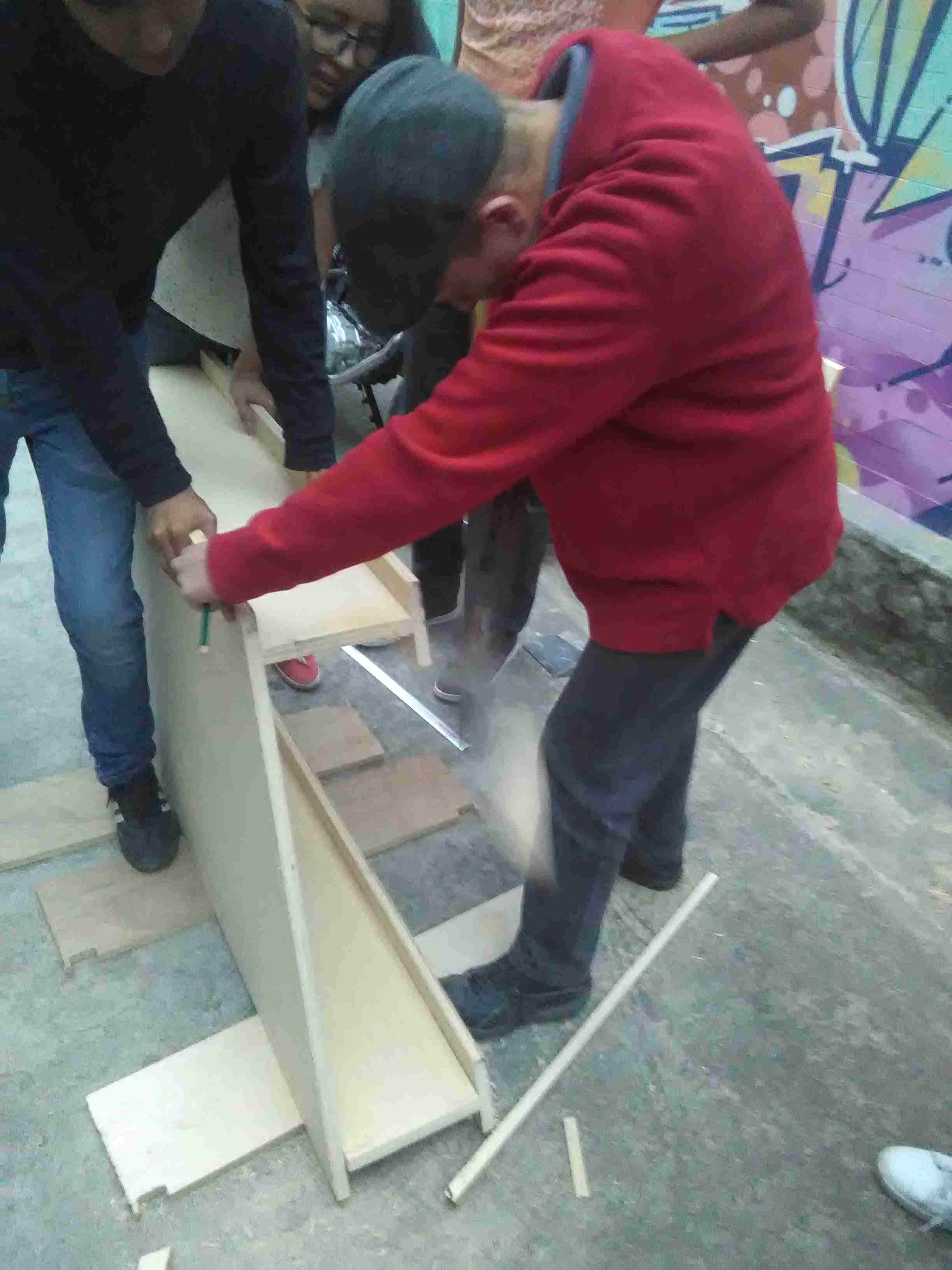
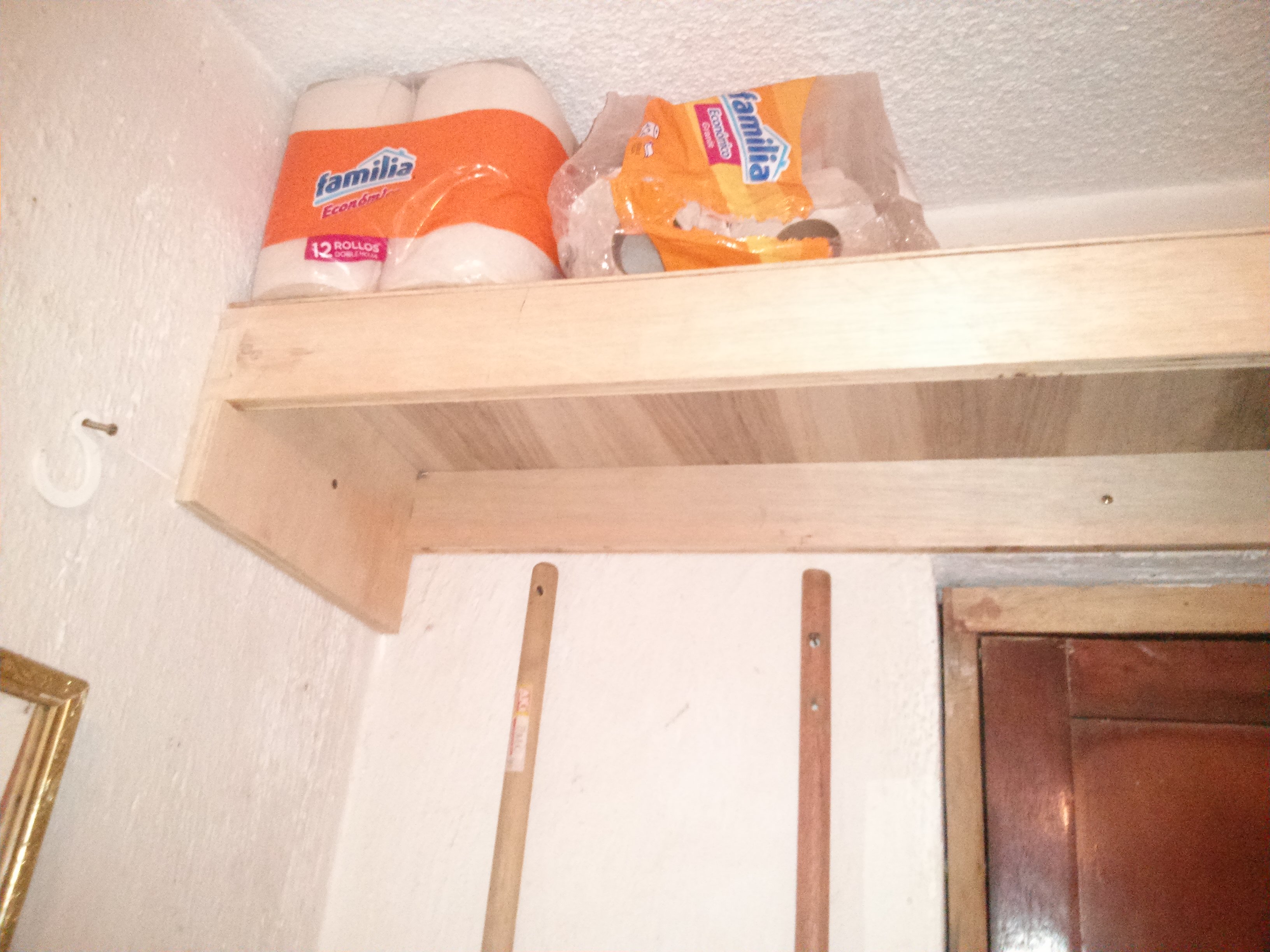
These are pictures of the assembled and mounted bathroom shelf.
Cut Depth should be equivalent to the tool diameter (as specified in the CNC Tips section of the Computer Controlled Machining tutorial). It sounds natural since the mill cuts horizontally and the depth it can cut can be as much as the width it can cut. But this must be verified in the specification sheet for the endmill and the router.
Stepdown must never be greater than 50% of the diameter of the mill unless the material is very soft.
In 3D milling, model placement must be at the bottom of the material's thickness. The contrary as in 3D printing.
An endmill is flat. Ramping moves are used on dense materials. These moves make milling easier on this type of mill.
Security height is established at 30 mm.
Upcut and downcut drill bits:
Stepdown is the vertical advance in each pass.
Stepover and overlap are the percentage of rework the mill does over its previous pass.
Offset is the distance between the center of two passes.
Feed is the horizontal speed.
Plunge is the vertical speed.
Spindle speed is the speed at which the mill turns.
Designs with diagonal press-fit.
First draft source file of shelf with each surface on its original assembly plane.
Designs with parametric measurement values specified on embeded spreadsheet and has ortogonal press-fit.
Parametric design source file of shelf with each surface on its original assembly plane.
Gcode file of 5mm board endmill paths.
Corrected Gcode file of 18mm board endmill paths.
Final (manually edited) version of Gcode file of 5mm board endmill paths.
Final (manually edited) version of Gcode file of 18mm board endmill paths.