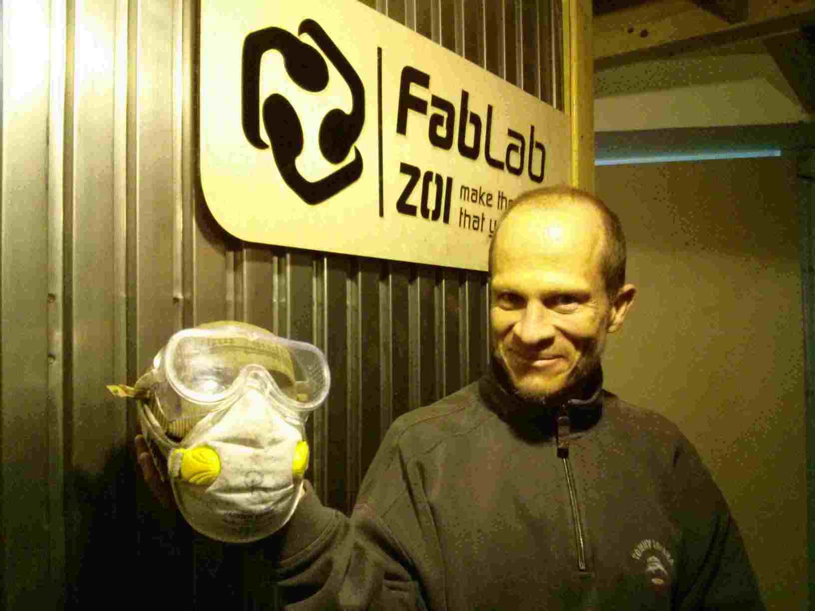
This assignment will lead us through computer-controlled cutting with a LASER machine and a vinyl cutter. I will hereby, describe the software used to design and how I calibrated these machines and cut these pieces. The press-fit pieces process is described. I will also detail how and what interfaces I used for connecting the cutting machine to my computer.
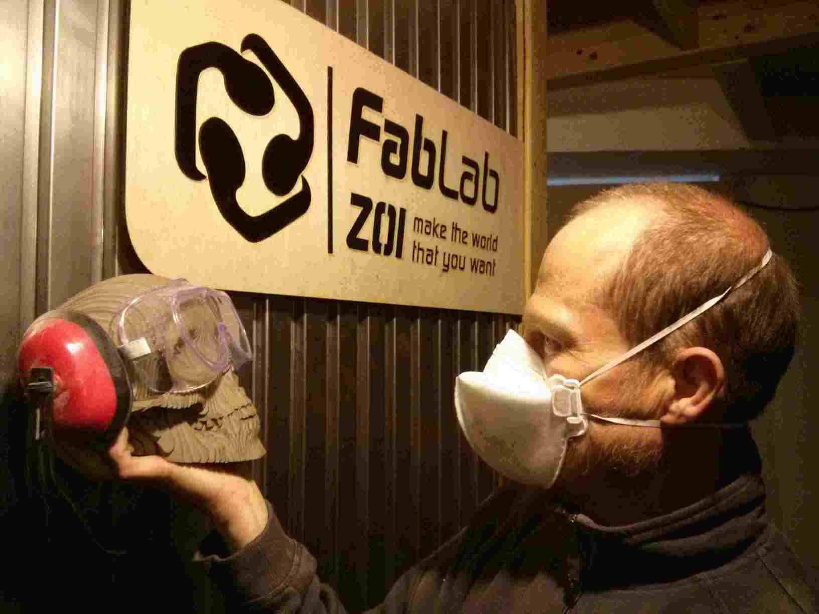
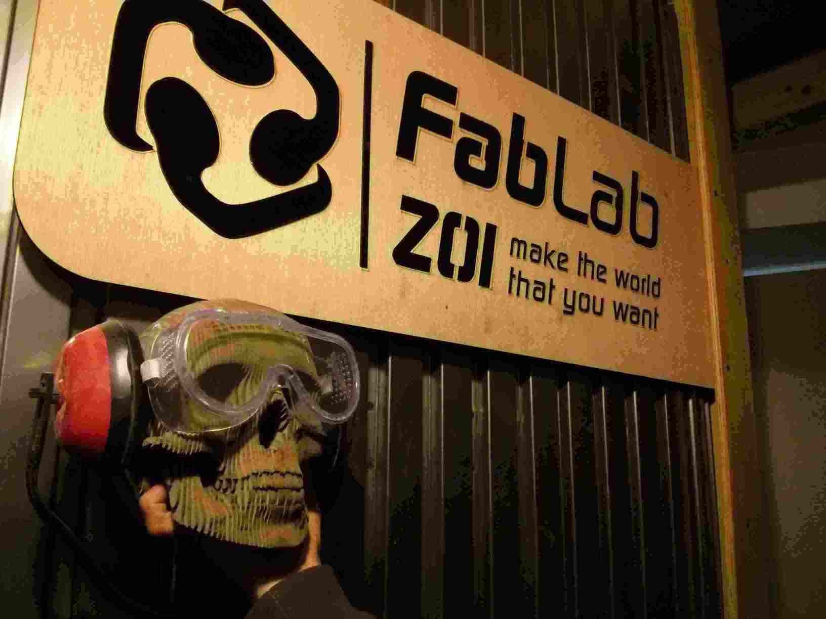
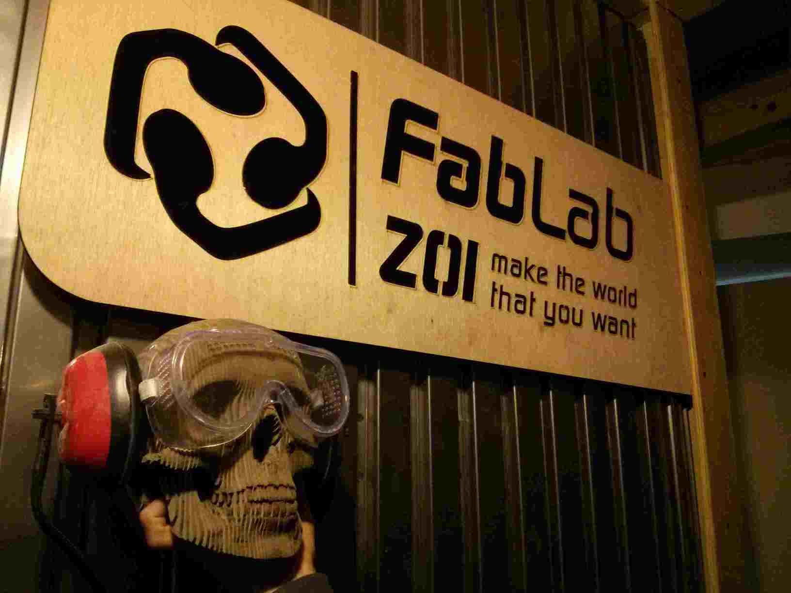
Computer-controlled cutting can make 2D pieces in order to construct 2D objects or or for integrating them and making 3D objects as can be seen on this skull.
Computer controlled cutting can be also be achieved with the CNC mill as described in the Computer-controlled machining definition and the image shown below.
I have learned cutting by control of the computer. The cutting machine works with a CO2 LASER (Light Accumulation by Stimulated Emission Rays). The machine has a long tube that shoots light. The light reflects on CO2 gas and shoots in a beam of parallel rays.
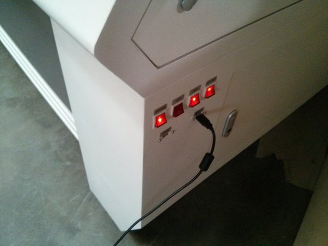
LASER is dangerous. So it must be used with an exact startup procedure.
It cools the LASER with water that circulates.
Extracts the gases outside of the room.
Removes the air from the zone that contacts the LASER. That prevents firing up the cut material with the machine.
Optional in order to see the cutting process.
It must not start up without previously:
I designed a piece on LibreCAD. It has different press-fiting gauge cuts for determining the width of the cut according to the thickness of the material. The process I followed on LibreCAD for designing the gauge piece was by drawing orthogonal vertical and horizontal lines as follows.


This link provides the above design of the test square in LibreCAD.
With this design I cut a wooden square of 5 mm thickness. The dimension of 20,00 mm resulted at 20,04 mm and 20,10 mm (~20,07 mm). The dimension of 40,00 mm resulted at 39,40 mm and 39,54 mm (~39,47 mm). We obtain it at 70% power and 8mm/s.
I tested with higher speed (10 mm/s) at 75% power. The dimension of 20,00 mm resulted at 20,04 mm and 20,20 mm (~20,12 mm). The dimension of 40,00 mm resulted at 39,68 mm kaj 39,50 mm (~39,59 mm).
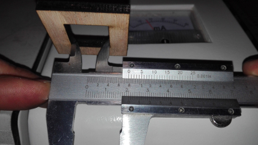 Mesurement with caliper
This tells us that the first time it was more precise. The error is 0,03 mm in one direction and 0,26 mm in the other. It could be caused by the direction of the wood fibers.
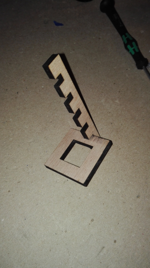
I cut the wood with notches of different thicknesses: 5,2 mm, 5,1 mm, 5,0 mm, 4,9 mm kaj 4,8 mm. Neither adjust. I cut another wood piece with notches of: 4,75 mm, 4,70 mm, 4,65 mm, 4,60 mm kaj 4,55 mm. The 4,65 mm adjusts very well.
These are the links to the first design of the thickness test and second one in LibreCAD.
I designed the piece to assemble with press-fit thickness of 4,65 mm. I used the following procedure with LibreCAD:
Circle and tangent

2 circles on 1 tangent

Removing the tangent line. We are left with 2 tangential circles.

Drew a third circle with 2 points and same radius.

Drew internal circles with a small displacement which will be half the length of the future joining sides.

Drew a triangle between the centers of the circles. Then I removed the external circles.


Trimmed the sides of the lines on the point of intersection with the circles.

Cut the circles and then trimmed the outer sides of the circles.

Drew a perpendicular through the middle of one of the future joining sides. Then drew 2 parallel lines at both sides at the same distance of the width of the material (4,65 mm).


Drew a line that defines the depth of the press-fit. Then removed the extra lines.


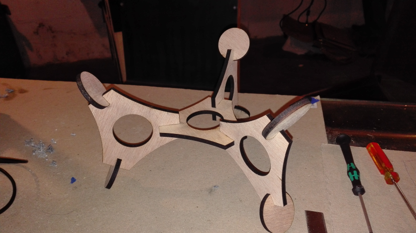
Drew lines that passed through the center of the figure by way of the angle (360 degrees divided by 3) and the centers of the future joining sides. Copied the press-fit by rotating the angle. Then removed the guide lines.


The piece was too big. Since LibreCAD is not parametric, I had to change the dimensions. To avoid a lot of work, I moved the press-fit designs with the center of the piece and a circle as guides.


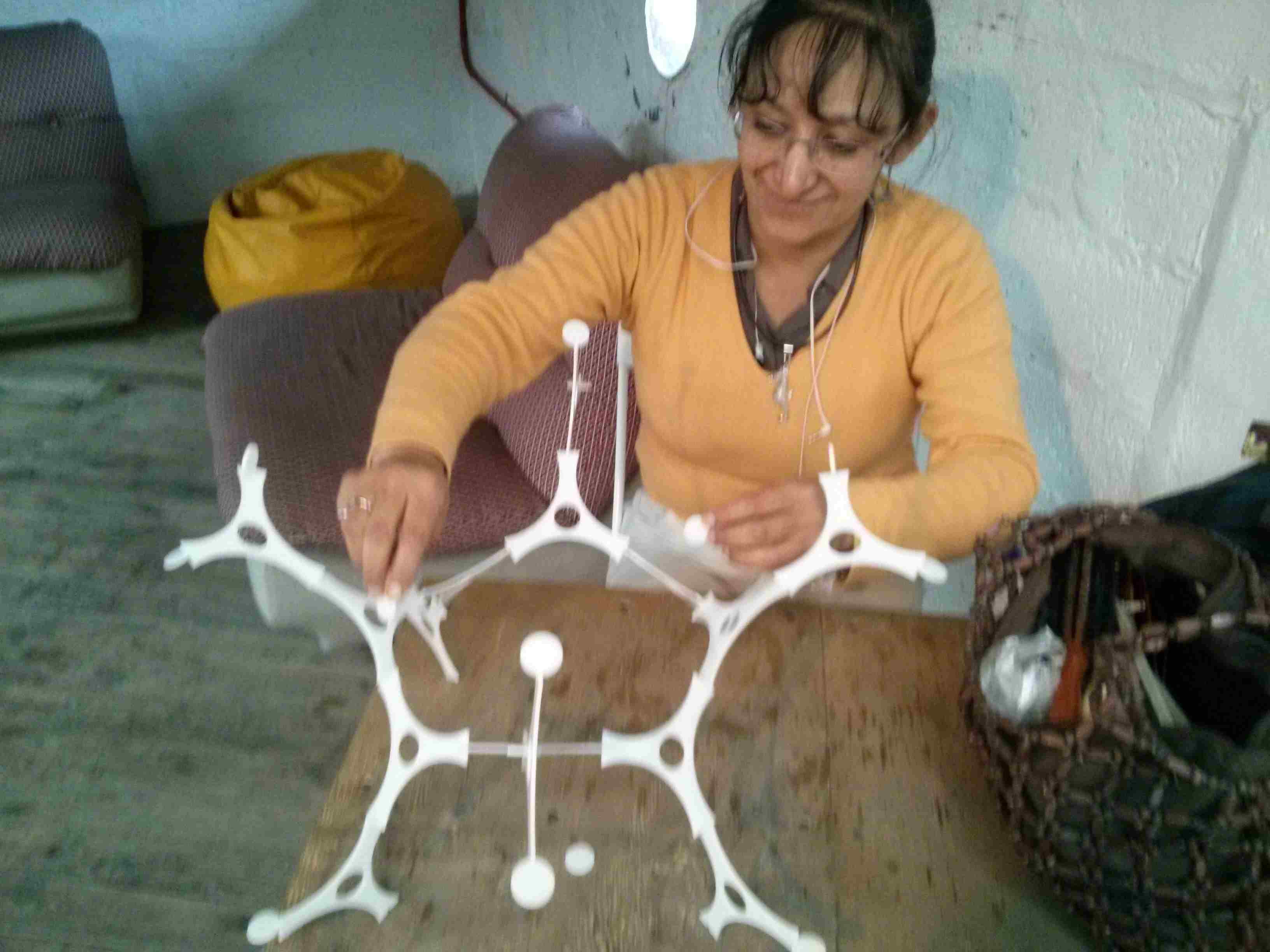
The pieces are cut and assembled.
These are links to the original design file of the press-fit piece in LibreCAD
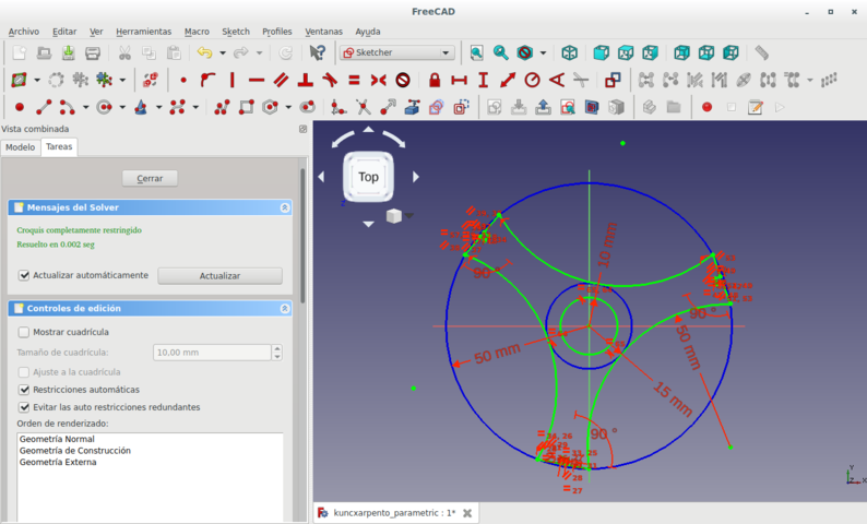
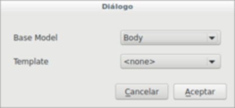
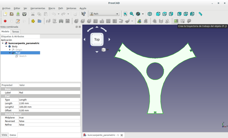
This time I made the same piece as before but I used FreeCAD in order to create a parametrized piece. This allows for changes in the dimensions of several segments by way of the definition of only one parameter. This is useful for example to change the design of press-fit in order to work with several thicknesses of materials.
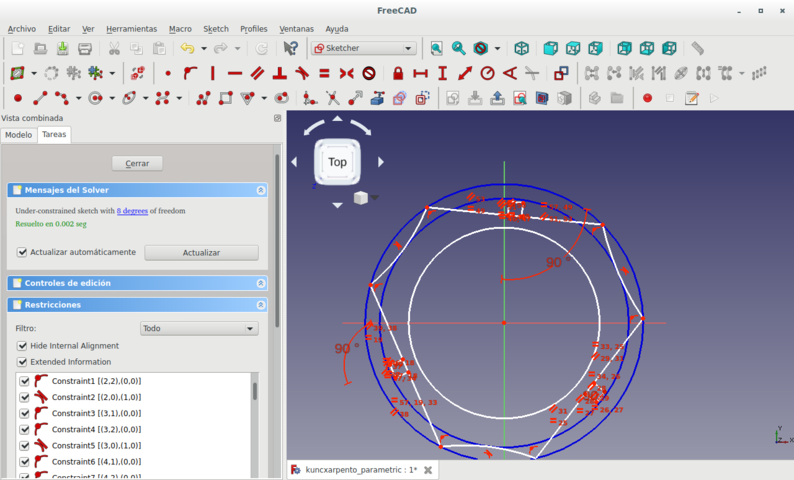
I made 3 concentric circles and an isosceles triangle with numerically changeble dimensions. It is a fully constrained sketch.
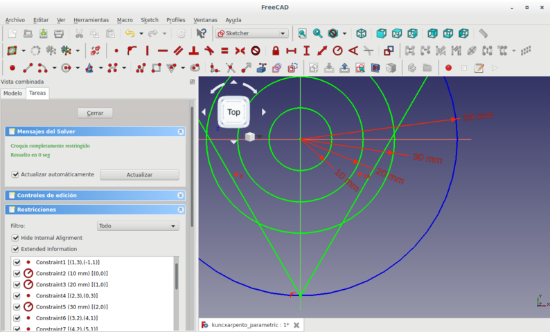
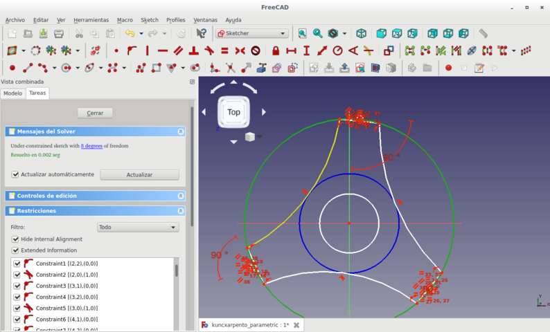
Then I made circles with their centers on the vertices of the triangle and made the triangle a construction object in order for it to be invisible. I constrained several parts (angles, lengths, distances) such that the elements would be symetric.
I played with the diameters of the circles in order to test this parametrization.
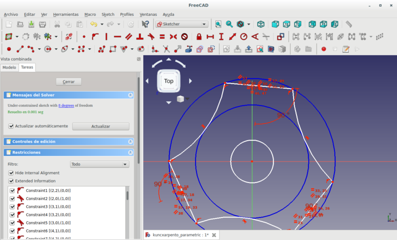
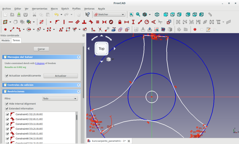
Then I proceeded to constrain the 3 arcs.
Again I played with the diameters of the circles.
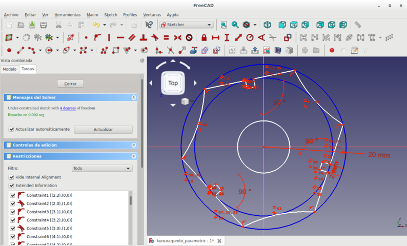
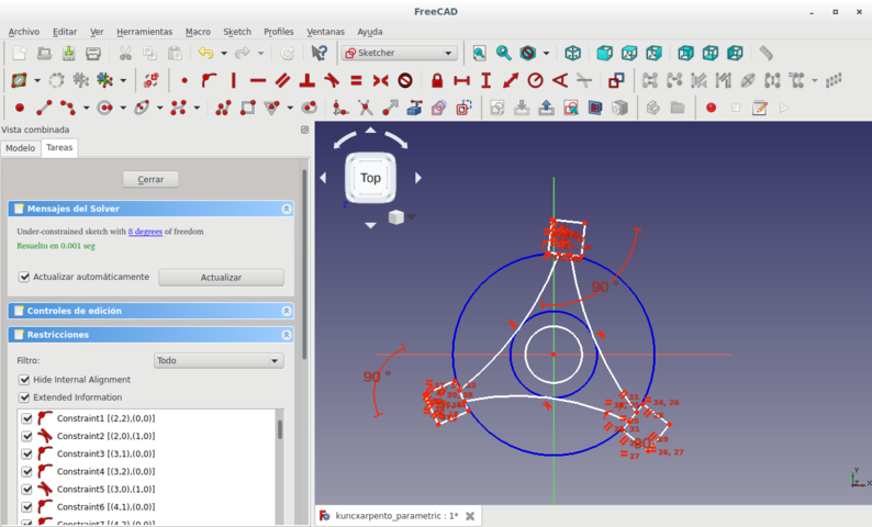
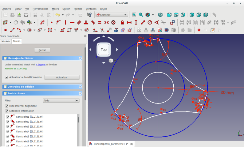
I fully constrained the sketch.
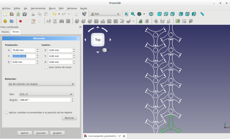
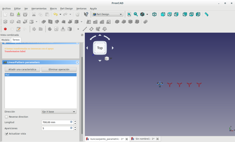
I used several techniques of transformation for fitting several copies of the parts into the available material.
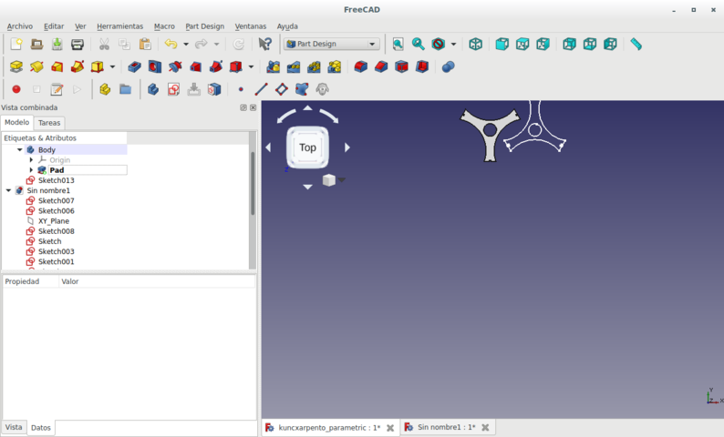
I even went as far as making a padding (giving volume to a 2D sketch.
Then I made a Gcode file in FabModules.
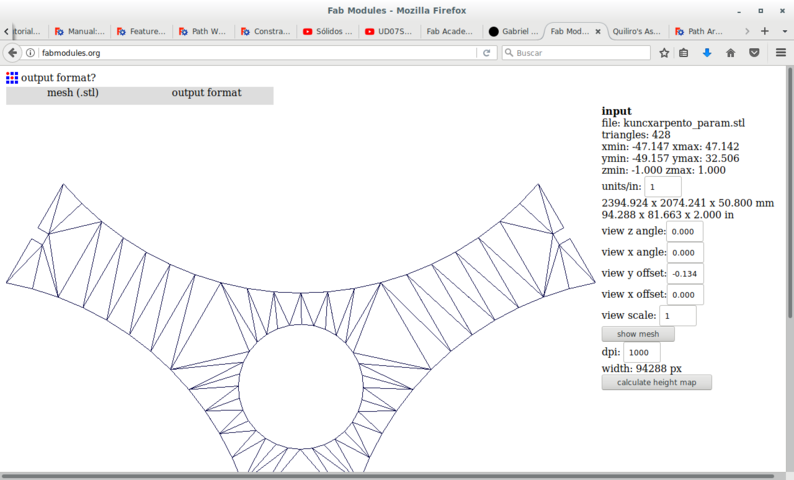
But finally the machine uses DXF files. So I made it in that format.
And fed it to the LASER cutter.
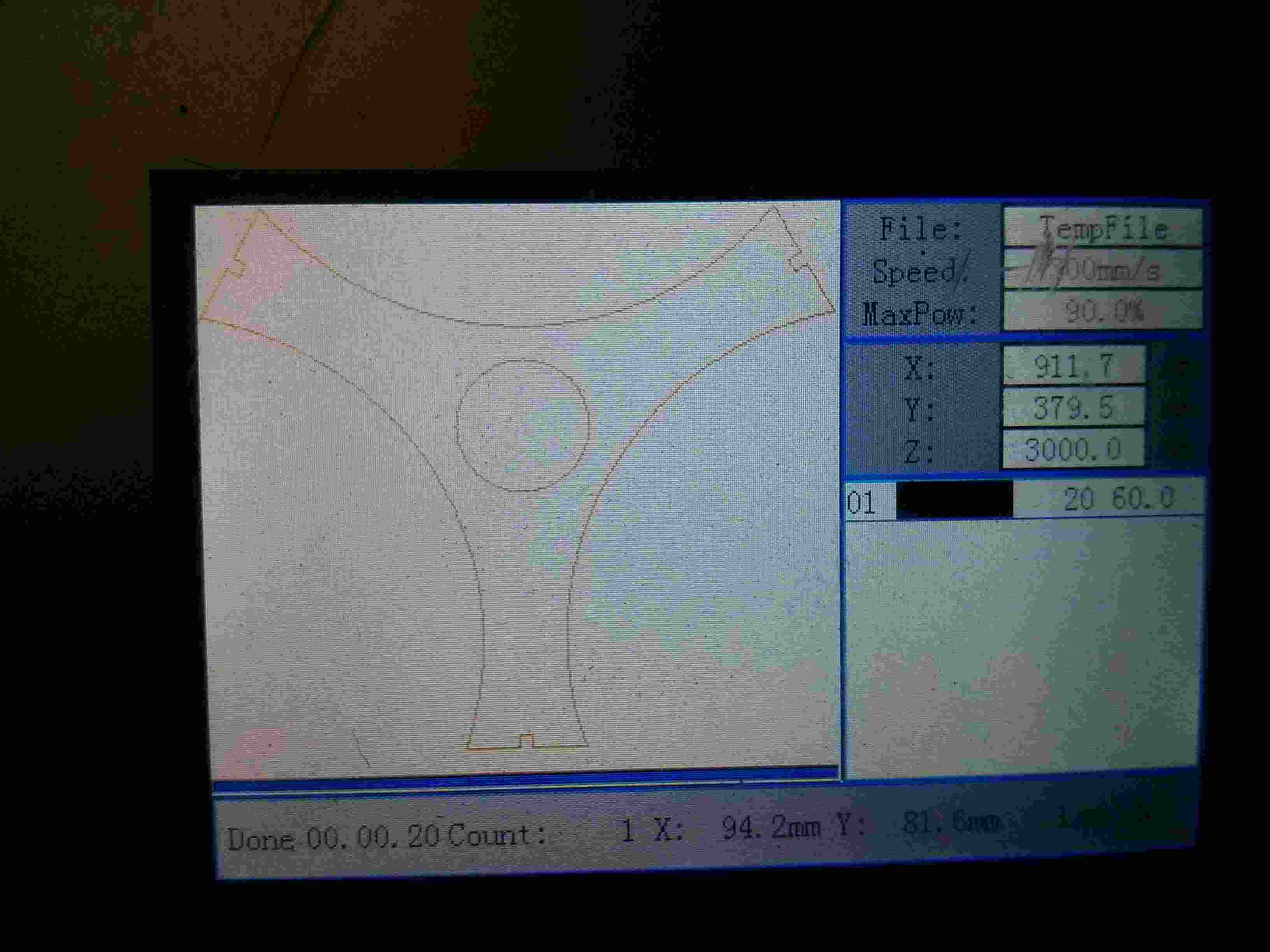
This image is from the LASER cutter's LCD.
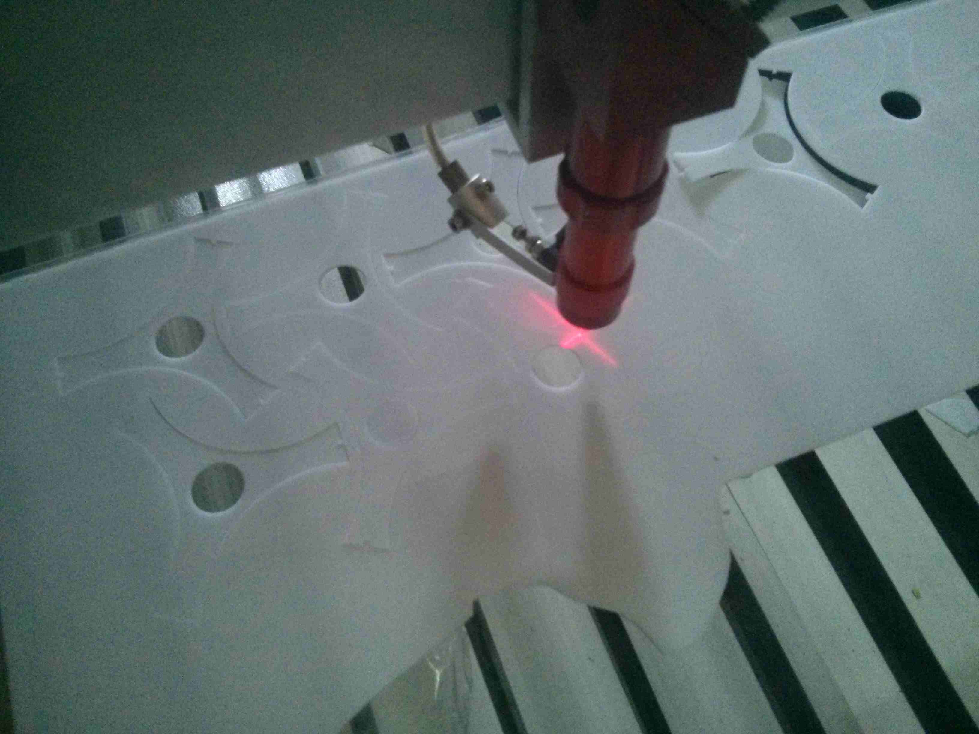
And the LASER is cutting.
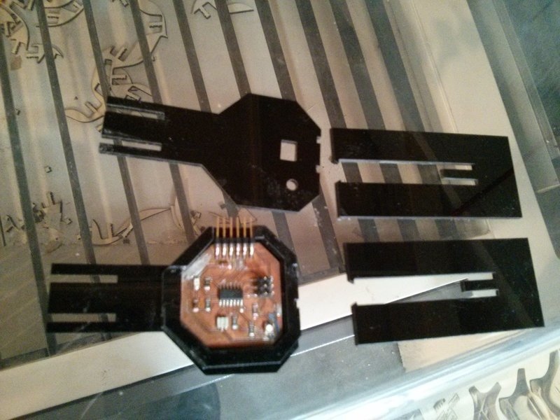
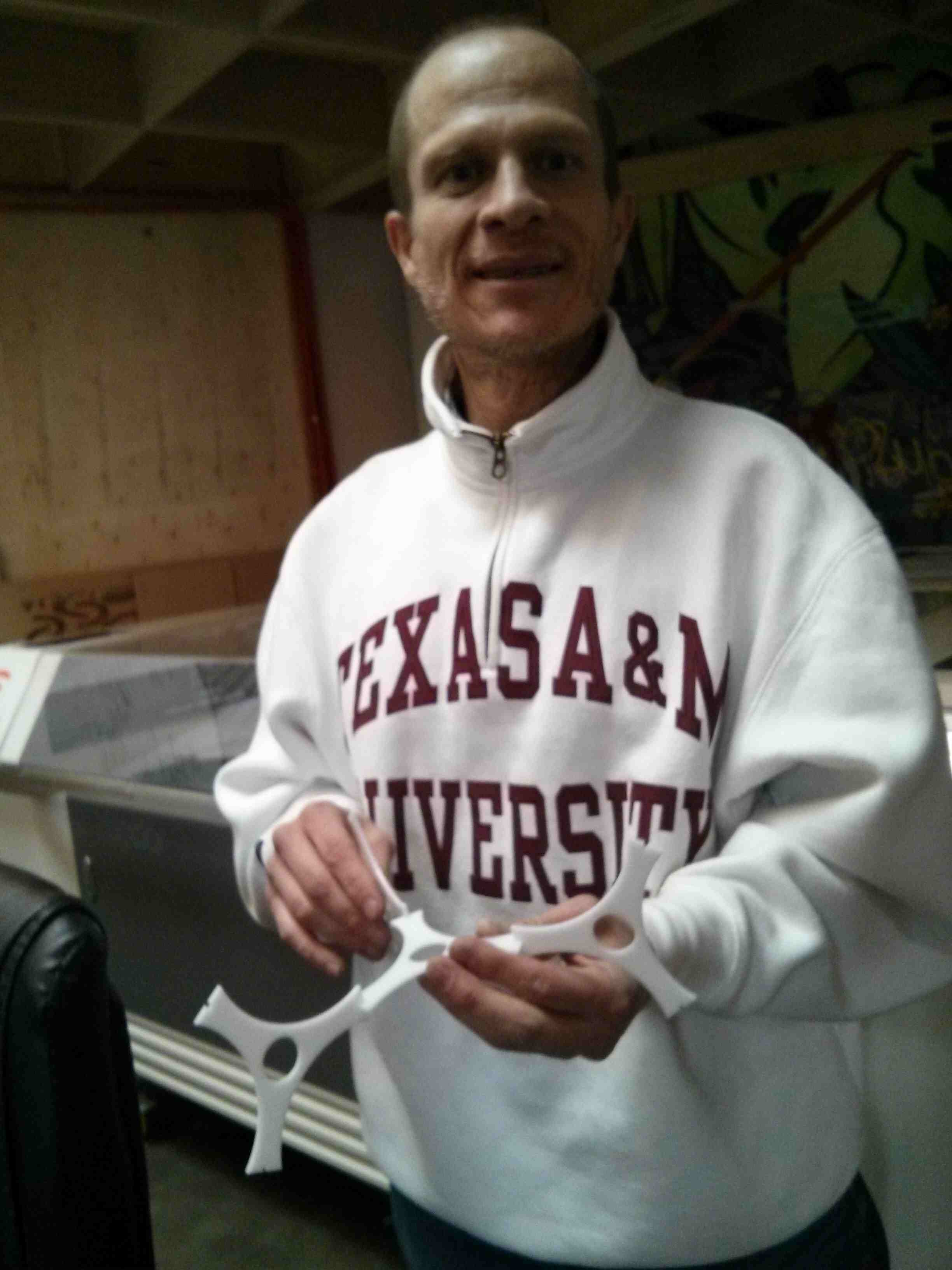
These are the pieces that were produced.
FabLab Zoi has the Silhouette Cameo vinyl cutter.
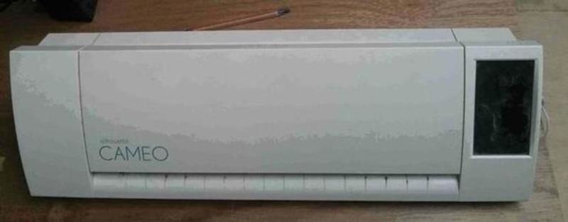
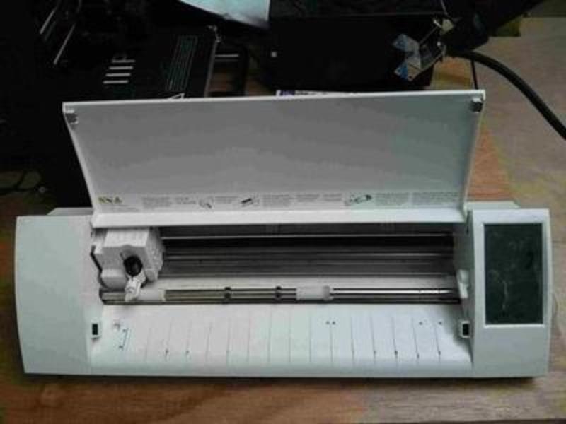
The vinyl cutter is a very simple machine. It has a vertical rigid needle which moves right and left. A set of rollers move the material to the front and to the back. That provides a 2 dimensional displacement that cuts the material where the needle travels in the horizontal plane.
Silhouette Cameo vinyl cutter's software is not libre software. So it captures the user by manipulating the user's data and by controlling the behavior of the machine the way the developer decides; not by user choice.
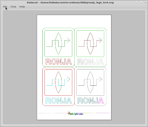
In order to cut (in freedom) with the available machine I tried RoboCut. It is a libre software which was designed for cutting. It advertises it is compatible with the Silhouette Cameo. It is a very easy and functional software:
Nevertheless, when I sent the program to cut,
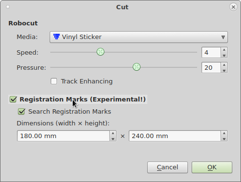
it does not detect the plugged device.
 .
.
So it did not cut.
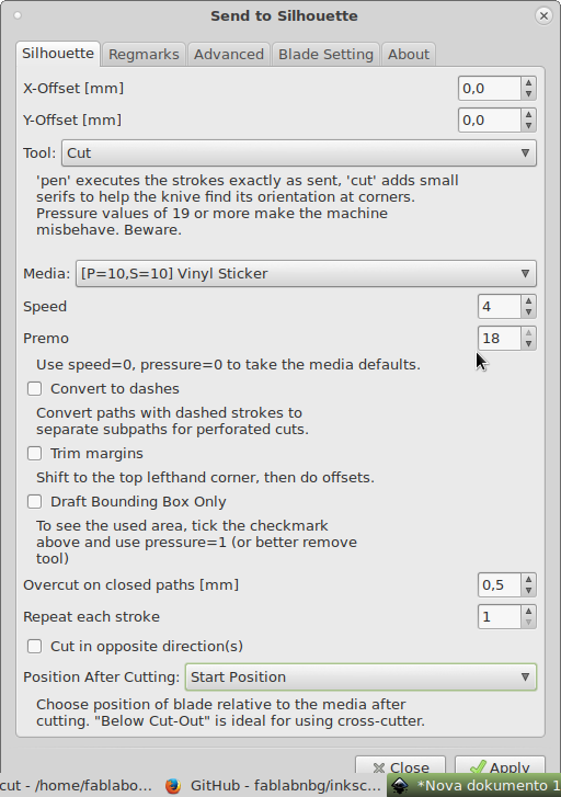
I tested another software: Inkscape Silhouette. It is a libre plugin for Inkscape that promises sending the loaded file to the vinyl cutter as if it were a printer.
      sudo apt-get install python-usb

      git clone  https://github.com/fablabnbg/inkscape-silhouette.git

      cd inkscape-silhouette/

      sudo python2 setup.py build && sudo python2

      setup.py install

      sudo cp sendto_silhouette.* /usr/share/inkscape/extensions/

      sudo cp -R silhouette /usr/share/inkscape/extensions/
Extensions -> Export -> Send to Silhouette
 .
.
It did not recognize the device either.
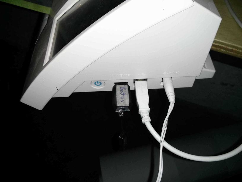
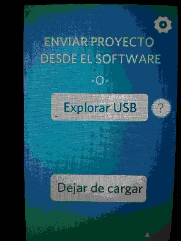
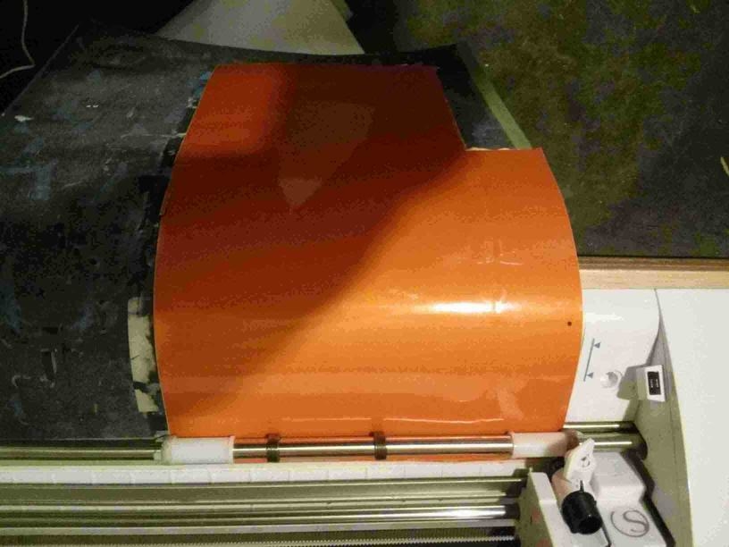
I decided to print directly from the machine's interface without installing software into my machine in order to avoid the vendor's intrusion into my computer. I saved the image file on a USB flash memory. Then I inserted the memory in the USB port on the printer.
I aligned the adhesive paper to the vynil cutter's feeder. When it detected the paper, the cutter showed a menu. I pressed the feed media button.
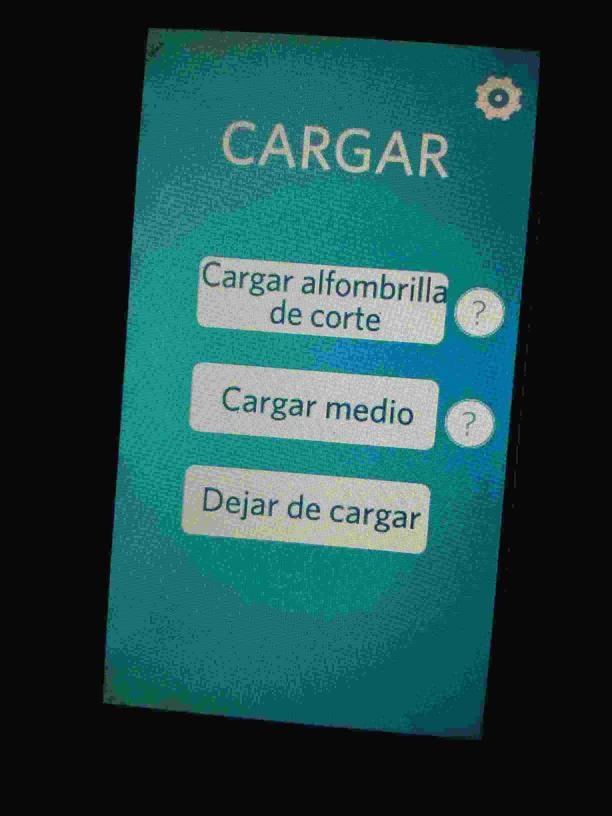
The cutter showed another menu when it detected that the media was loaded and asked if it should finish the load process.
The paper was not fed correctly because it was not fed by both feeder wheels. It curves and makes distorted cuts.
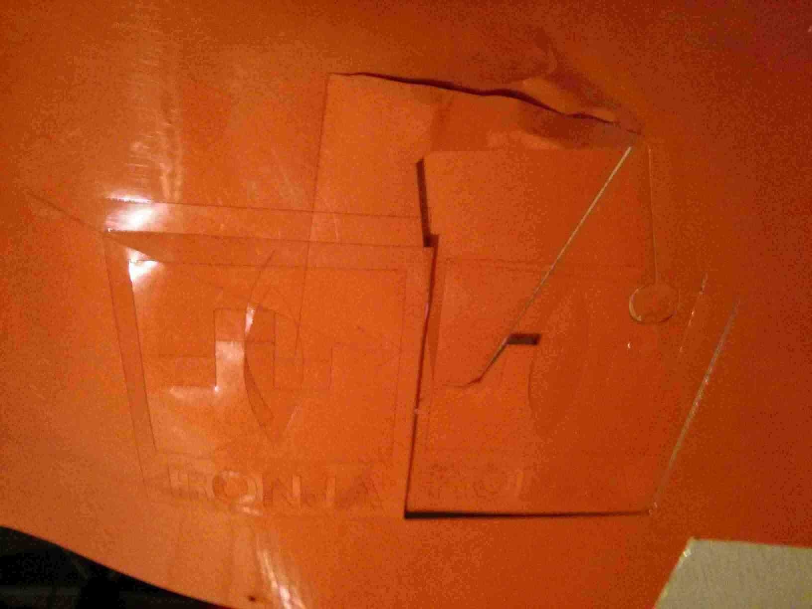
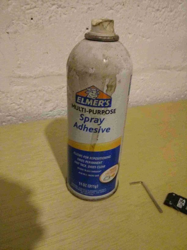
Then I used a spray adhesive.
to stick the paper to a larger sheet of X-ray film.
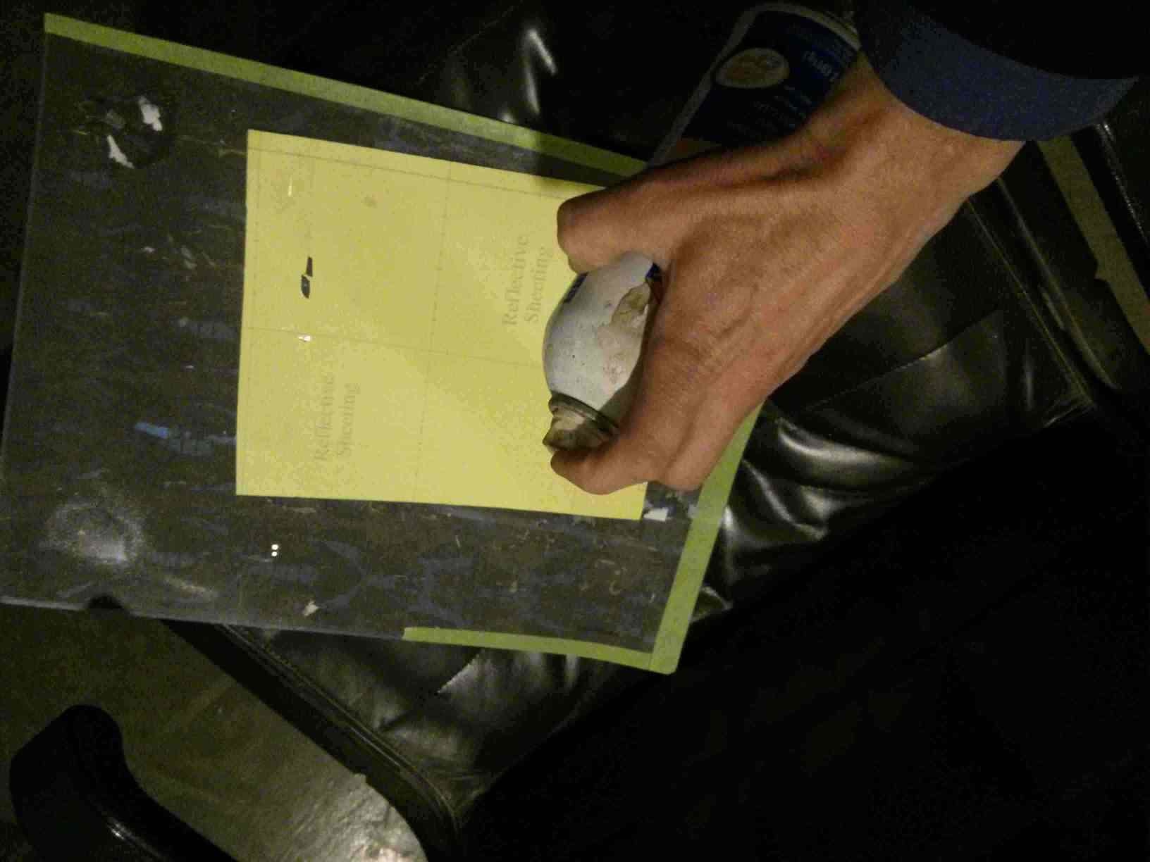
It worked!
The paper fixed to the sheet of X-ray film is loaded. It can now engage both feeder wheels.
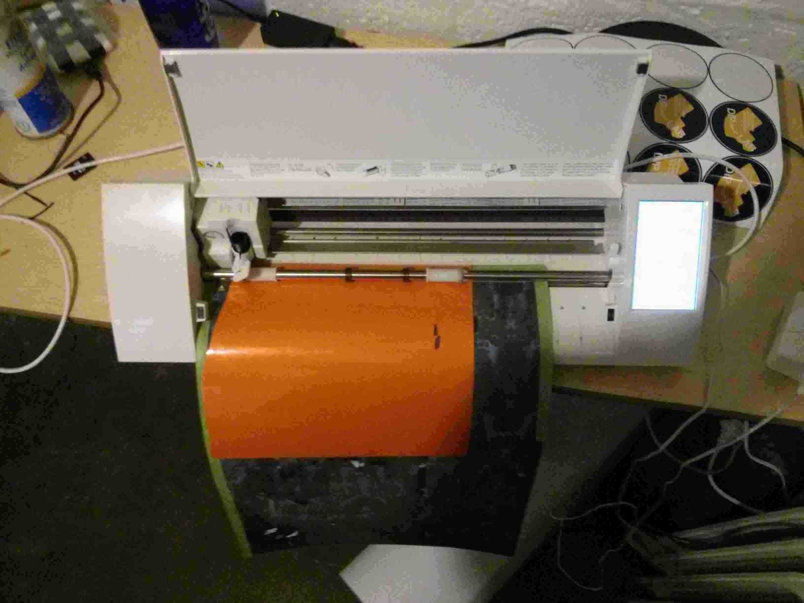
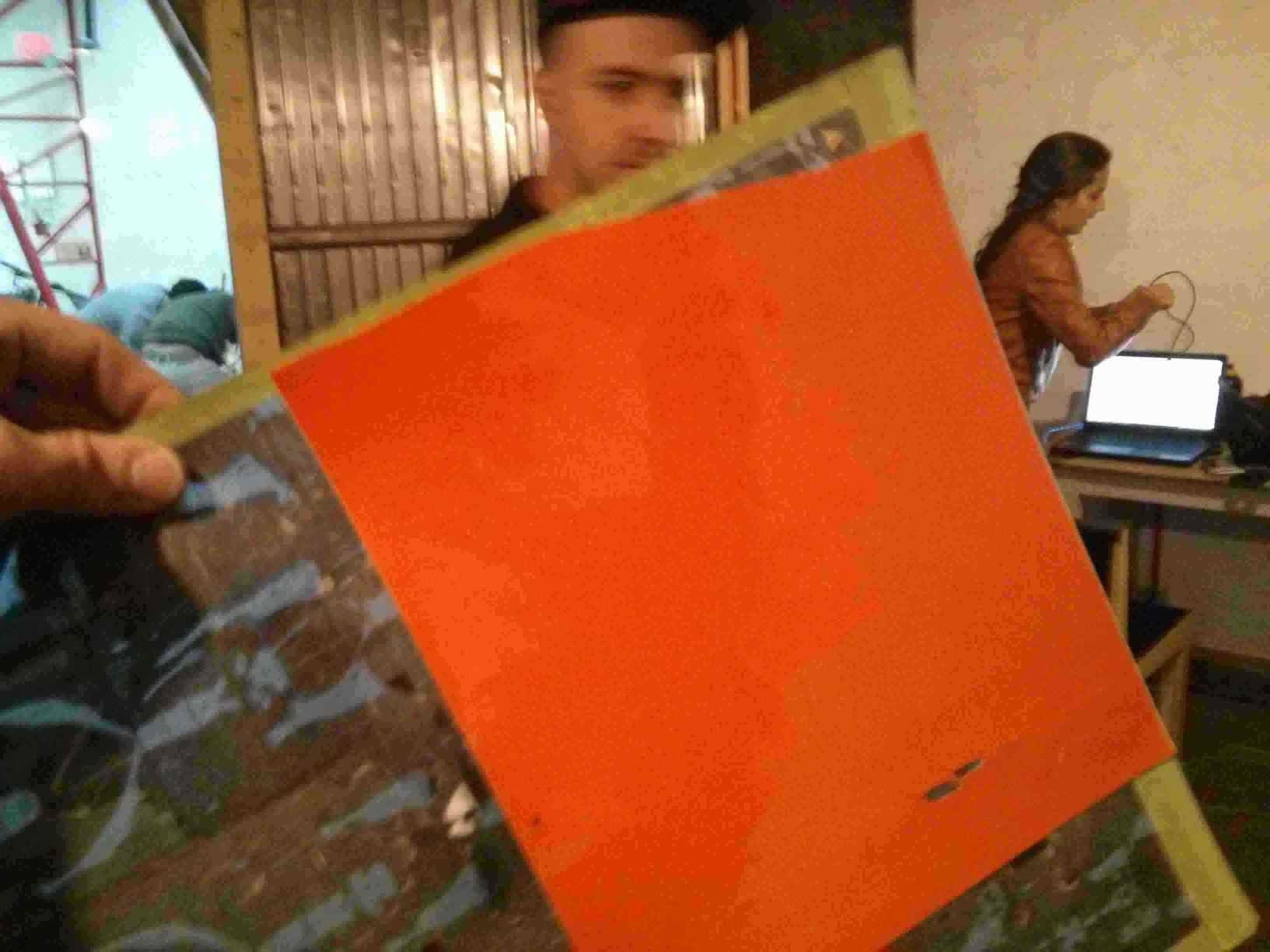
And the printer could cut the design.
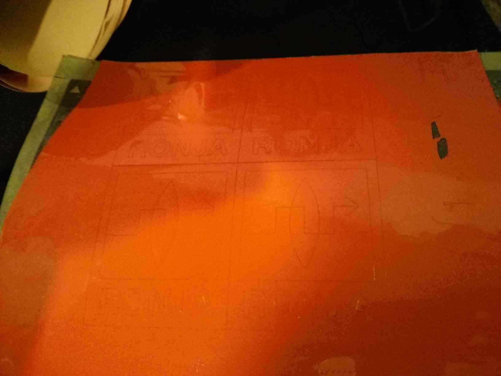
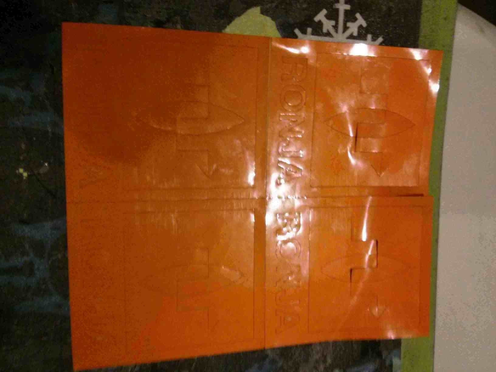
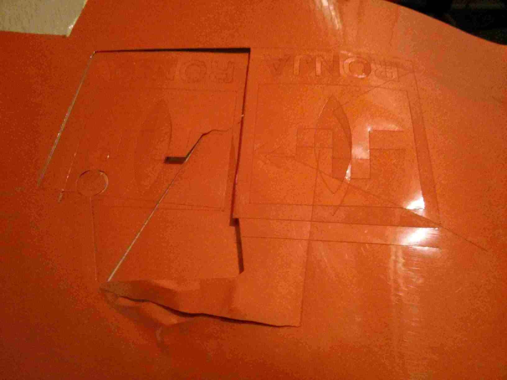
This is the sticker acomodated in order to show the sticker design.
I had to separate the parts in order to make the contrast visible. But that is a question of design, not of the cutting process. The important thing is that this process can be valuable to cut copper traces for PCBs and to make branding.
This link provides the design of the test square in LibreCAD.
This is the original design file of the press-fit piece in LibreCAD
And this is the parametric press-fit piece in FreeCAD.
The vynil cut piece image to cut.