NETWORKING AND COMMUNICATIONS
For the assignment this week we need to send a message between two projects, in the same way I have to design and build a wired or wireless network that connects at least two processors.
Learning outcomes:
Demonstrate workflows used in network design and construction
Implement and interpret networking protocols
Individual assignment
Design and build a wired &/or wireless network connecting at least two processors
For this week I want to communicate several cards for I²C and rs232 communication, I am presented with a challenge, I try to create a device that communicates the use of LUFA communication; at this moment it is complicated, but I will try it for another weeks , I had never heard it that way, I want to work on this type of communication. Look at the FAB ACADEMY projects from other years and I found a device that uses this communication and uses it to convert it into an FTDI communication. It is known as FABFTDI, although I found two designs on the network. I liked the one that the Attiny45 uses the most.
Making a USB device requires programming a microcontroller that can communicate with a computer with the USB protocol. So far in the classes, we have been writing a microcontroller code that communicates with several protocols, such as RS232, I²C or SPI but it is also possible to do it with USB.
I²C
According to Arduino on his page https://playground.arduino.cc/Code/USIi2c he mentions that
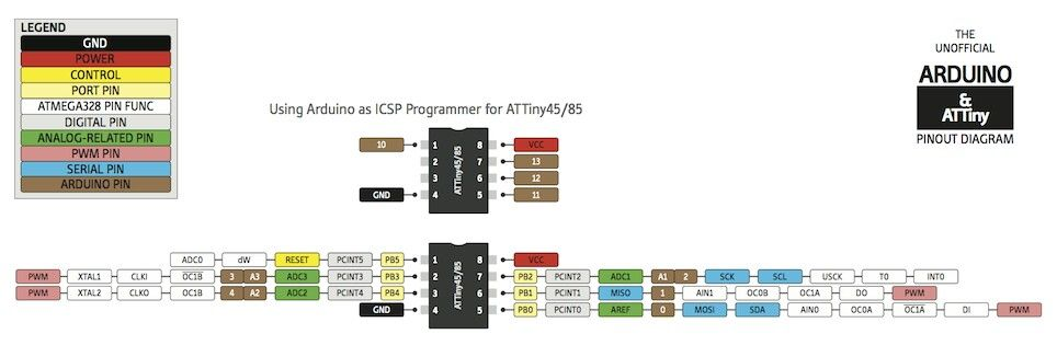
"The ATtiny85 microprocessor is an 8 pin chip with 6 (max!) I / O ports. Using an I²C bus greatly expands the possibilities of what you can do with this chip. The ATtiny85 (and it's cousins) does not have I²C (or SPI) "built in". Instead it has to Universal Serial Interface (USI) that can be used to facilitate I²C and SPI. "
Configuration
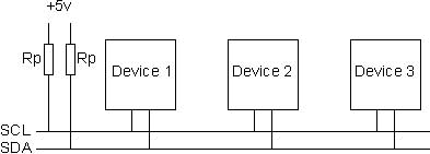
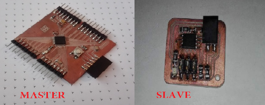
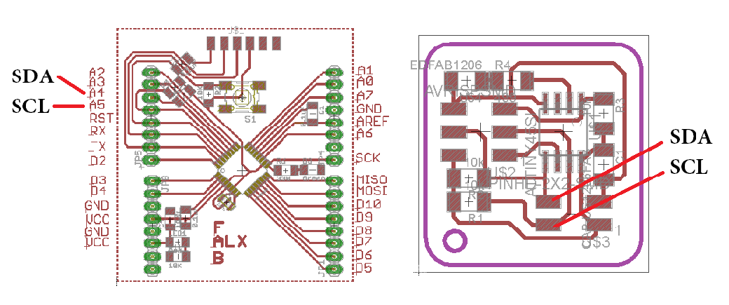
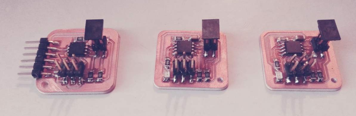
Each I²C bus consists of two work pins: SCL and SDA. SCL is the clock signal and SDA is the data signal. First I will communicate 2 devices. It is necessary to use 2 resistors of value 4.7K as the diagram that is shown in the datasheet. I create 3 boards1 cards that are configured as master and 2 as slave.
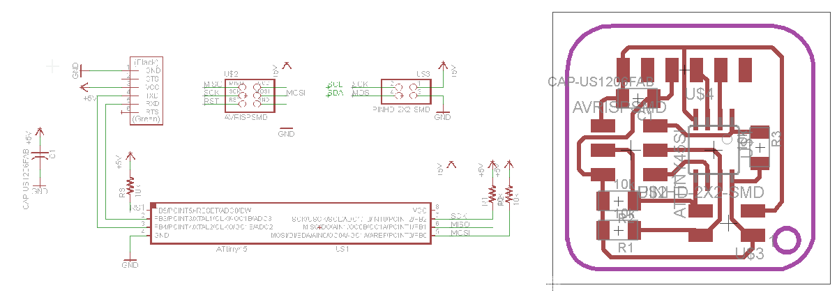
On my master plate I added the i2c communication pins and the serial communication pins for the ftdi. How to mill it I explained it in week 5 - Electronics production so I will leave the designs.
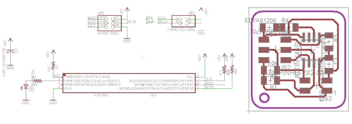
On my slave board I added the i2c communication pins and an LED that will allow me to interpret if the communication was fulfilled. In the same way I leave the original designs to be able to mill them.
To enter the programming we need some requirements: as a most important point the libraries
For my master board
According to information provided by microchip, he mentions that:
"The bus allows simple,robust, and cost-effective communication between integrated circuits in electronics. The strengths of the TWI bus are its capability to address up to 128 devices using the same bus and arbitration, and the possibility to have multiple masters on the bus. The Two-wire Serial Interface (TWI) is ideally suited for microcontroller applications. The TWI protocol allows the systems designer to interconnect up to 128 individually addressable devices using only two bidirectional bus lines; one for clock (SCL) and one for data (SDA). The only external hardware required to implement the bus is a single pull-up resistor for each of the TWI bus lines. All devices connected to the bus have individual addresses, and mechanisms for resolving bus contention are inherent in the TWI protocol."
(Atmega 328p) and ATtiny45 "Master and Slave"
First I communicate my FabALX board which consists of an atmega328p and I configure it as a master, I communicate it with my slave board that costs an attiny45. FabALX is a design created by me but with the appearance of an arduino, clear the order of the pins do not coindicen but esno has nothing to do with the operation. More information in the week of Input devices.
Something very important to take into account is that each slave must have an identifier or an address. In Arduino ide this address is configured with the following code #define I2C_SLAVE_ADDRESS 0x6 0x6 would be the address that I add. The number has to be in hexadecimal.
Master code
#include "Wire.h"

void setup()
{
  Wire.begin(); // Start i2c bus
  Serial.begin(9600); // start serial for output
}

void loop()
{
  Wire.requestFrom(6,1); // request 1 byte from slave device address 6
  while(Wire.available()) // slave may send less than requested
  {
    int x = Wire.read(); // receive a byte as character
    Serial.println(x); // print the character
  }
  delay(500);
}
Slave code
#include "TinyWireS.h"      //library for Attiny as slave
#define I2C_SLAVE_ADDRESS 0x6 // Address of the slave

int x=0;

void setup()
{
  TinyWireS.begin(I2C_SLAVE_ADDRESS); // start i2c network as slave
  TinyWireS.onRequest(requestEvent);
  pinMode(PB4, OUTPUT);           // Turn on LED when program starts
  digitalWrite(PB4, HIGH);
}

void loop()
{
  TinyWireS_stop_check();
}

// Gets called when the ATtiny receives an i2c request
void requestEvent()
{
  TinyWireS.send(x);        //send a byte over to master
  x++;
}
Test
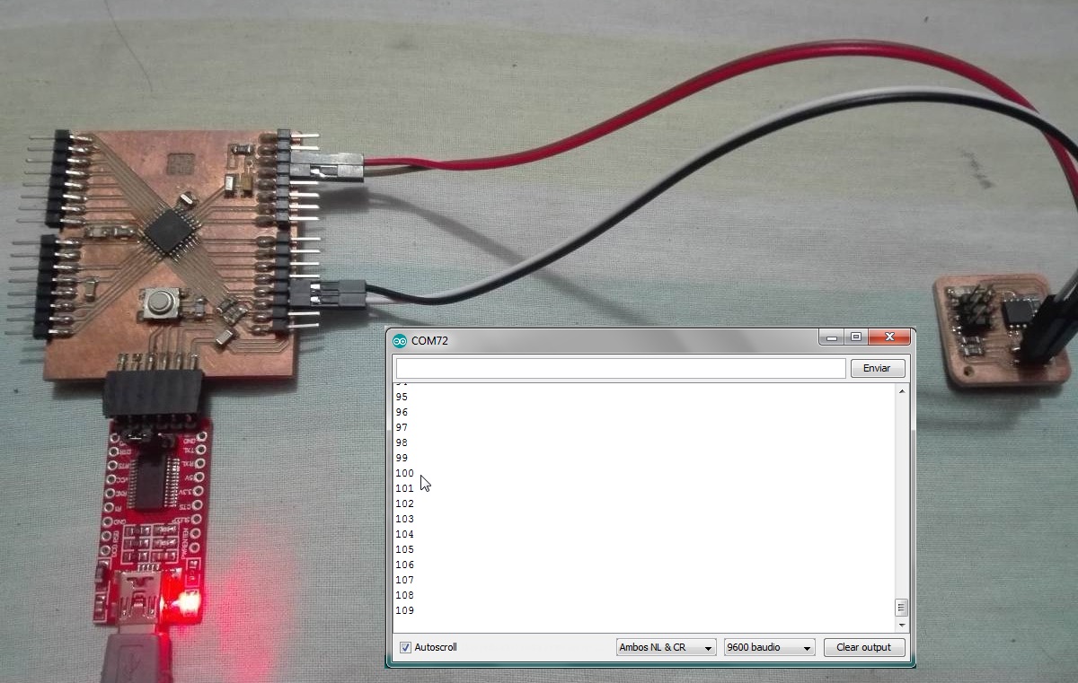
I²C between 1 Master and 2 slaves
The board master will communicate with the slave boards that join the network by sending "1" and "0" that allows turning on or off the led of the board, this board returns the message "ON" or "OFF" through FTDI and it is displayed on the serial monitor.
#include "TinyWireM.h"
#define device (1)
#define slave (2)
void setup()
{
    TinyWireM.begin();
}

 void loop()
{
    TinyWireM.beginTransmission(device);
    TinyWireM.send(1);
    TinyWireM.endTransmission();
    inputmsg1();

    TinyWireM.beginTransmission(device);
    TinyWireM.send(0);
    TinyWireM.endTransmission();
    inputmsg1();

    TinyWireM.beginTransmission(slave);
    TinyWireM.send(1);
    TinyWireM.endTransmission();
    inputmsg2();

    TinyWireM.beginTransmission(slave);
    TinyWireM.send(0);
    TinyWireM.endTransmission();
    inputmsg2();
}

void inputmsg1()
{
  volatile byte msg =0;
  TinyWireM.requestFrom(device,1);

  if (TinyWireM.available()){
    msg = TinyWireM.receive();}
  if (msg ==2){
    mySerial.println("Slave 1 LED On");}
  else if (msg ==3){
    mySerial.println("Slave 1 LED Off");}
  else
    {}
}

void inputmsg2()
{
  volatile byte msg =0;
  TinyWireM.requestFrom(slave,1);

   if (TinyWireM.available()){
    msg = TinyWireM.receive();}
   if (msg ==4){
    mySerial.println("Slave 2 LED On");}
   else if (msg ==5){
    mySerial.println("Slave 2 LED Off");}
   else
    {}
}
Serial communication
This data transmission does not generally use a clock signal, the data can be sent constantly. An important data for this type of communication is that the data is transmitted at regular intervals, this allows us several the number of bits to transmit, in addition that the transmitter does not have to be synchronized with the receiver.
The same boards used for i2c communication are configured to perform serial communication. The first is to configure the card that will communicate by ftdi and the second will be the node card, I have two cards of these.
The configuration of pin
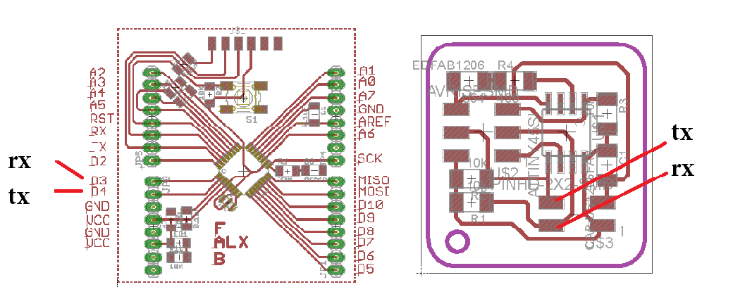
I make the test for the 1 board and verificate the resistor don´t have problem with the comunication. I making the code for my board FABALX and the code for 1 of my node boards.
Bridge code
#include "SoftwareSerial.h"
#define RX    3   // *** D3, Pin 2
#define TX    4   // *** D4, Pin 3
SoftwareSerial mySerial(RX, TX);


void setup()
{
  Serial.begin(9600);
  mySerial.begin(9600);
}


void loop()
{
  if (Serial.available()>0)
  {
    mySerial.write(Serial.read());
  }
  if (mySerial.available()>0)
  {
    Serial.write(mySerial.read());
  }
}
Node code
#include "SoftwareSerial.h"
SoftwareSerial mySerial(PB2, PB0);

char node = '1';

void setup()
{
  mySerial.begin(9600);
  pinMode(PB3, OUTPUT);
  digitalWrite(PB3,LOW);
}

void flash()
{
  digitalWrite(PB3,1);
  delay(500);
  digitalWrite(PB3,0);
}


void loop()
{
  if (mySerial.available())
  {
    char i = mySerial.read();
    if(i==node)
    {
      mySerial.print("Node 1");
      flash();
    }
  }
}
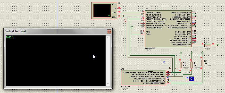
I maked the simulation of system with proteus this is util for verificate the correct work.
Simulation
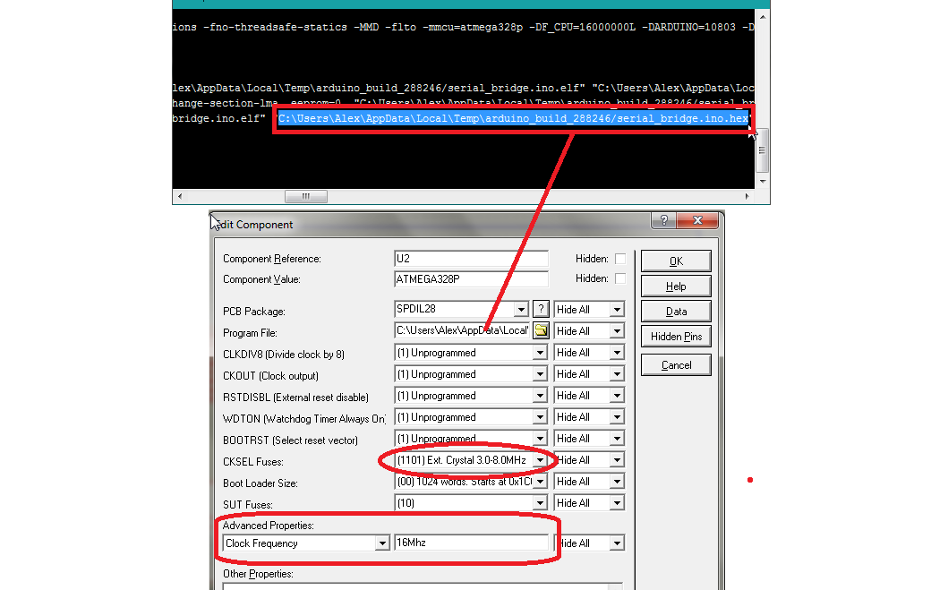
Configuration of bridge
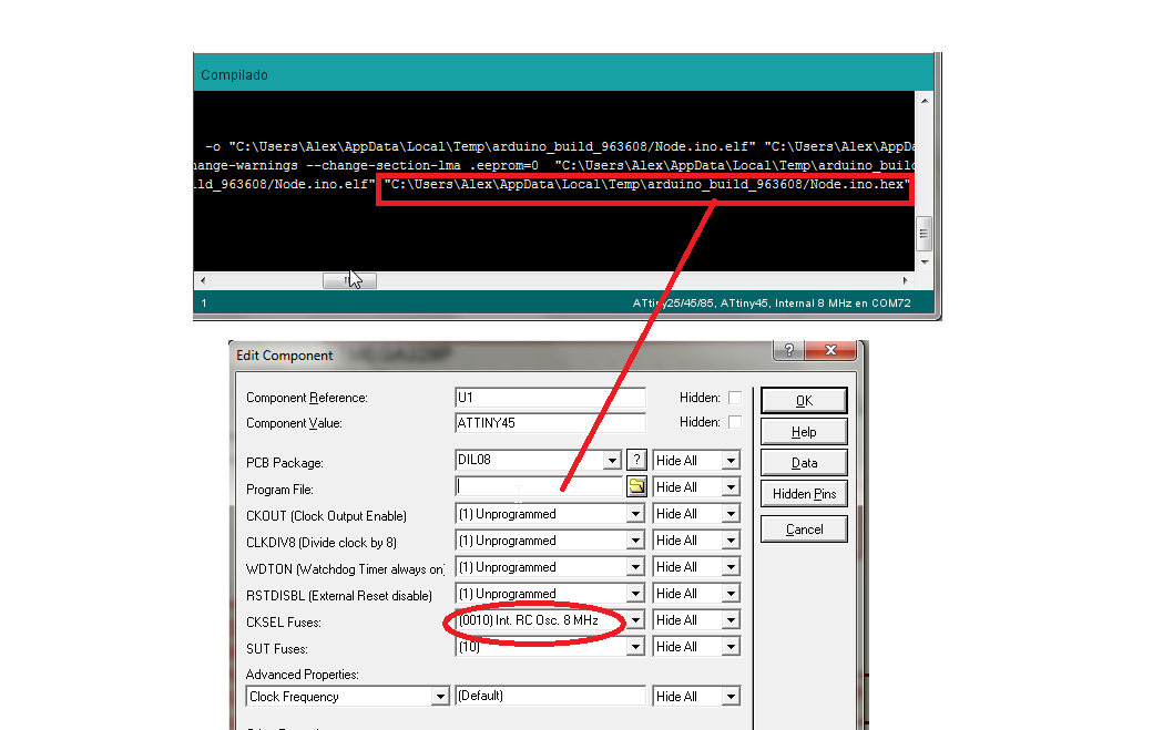
Configuration of node
Connection and test
Conclusions
A communication network will always consist of three essential components: transmitter, transmission channel and the receiver.
Making a communication system is not quite so simple I wanted to try several systems but I did not achieve it, with time I will learn more.
I was surprised that there are communication systems that I did not know, I would like to investigate correctly the devices with LUFA communication
The main difference between I2C and serial is that serial communication is a point-to-point or one-to-one connection while I2C is a bus that supports many devices, each with its own address.
I2C has a better speed, but the serial admits to transmit long distance cables, it depends on what your needs are.