JED PRO
Now I will describe the process of design and construction of each of the elements of the Didactic Electronic Toy for the teaching of programming to children all ages, in the process will be taken into account the choice of material according to the toy. different elements or electronic devices that best adapt to the proposal so that they allow to have a good functioning of the device.
Project general description
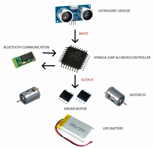
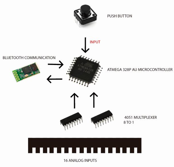
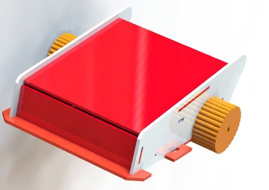
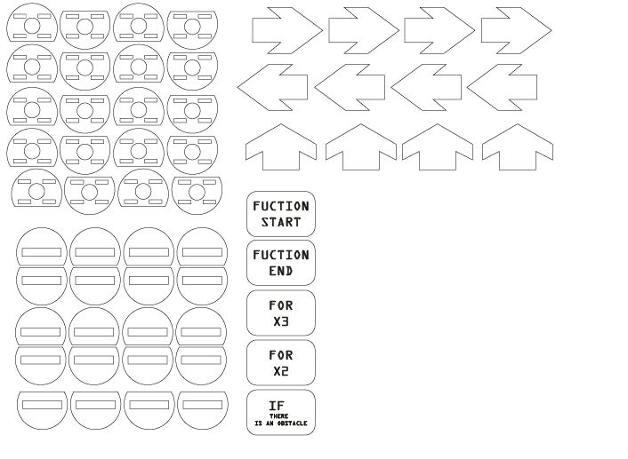
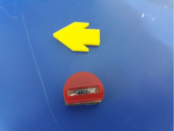
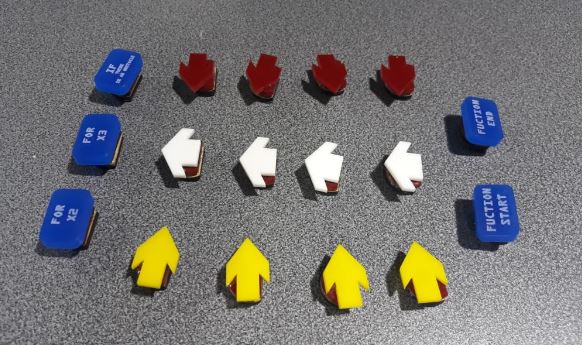
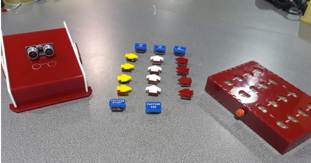
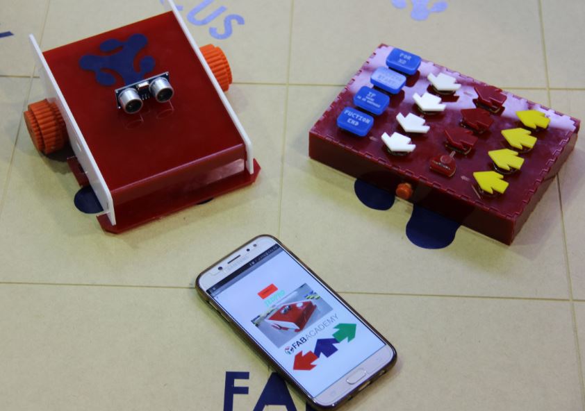
In the present prototype which will be called by its acronym in Spanish JED-Pro (Programmable Electronic Teaching Toy) has as its main characteristic the logic of tangible programming for children. This logic of programming is based on small pieces of instructions with different resistive value, which are inserted in an electronic board in the form of a sequence to be read through the analog pins of the microcontroller.
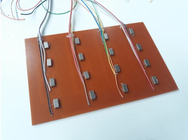
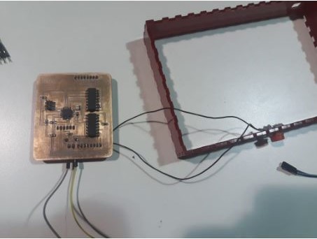
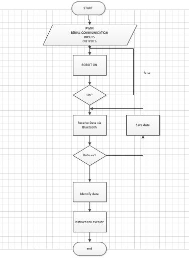
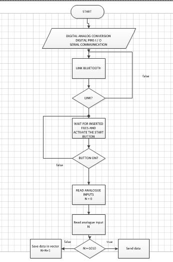
The instruction parts are inserted into the programming interface, which consists of 16 inputs and a control circuit based on the Atmega 328 microcontroller. This control circuit is responsible for reading the resistive value of each inserted instruction and relates the value read with the value of the previously assigned instructions. After identifying, the instructions are stored temporarily in a vector housed in the flash memory while you finish reading all the instructions. Once the instruction reading is complete, it proceeds to send the instructions one by one through the serial port connected to a wireless module to the robot represented by a cart that proceeds to execute the instructions one after the other until the sequence is completed. . All this process is done in milliseconds once the child press the start button also located on the board.
The robot receives all the instructions and stores them in a vector in the order in which they were received for later execution, among the instructions that the robot can execute are: Forward Advance, Turn Right and Turn Left; These are the basic instructions which can be accompanied by repetitive or conditional control structures such as IF and FOR
Selection of main components and materials
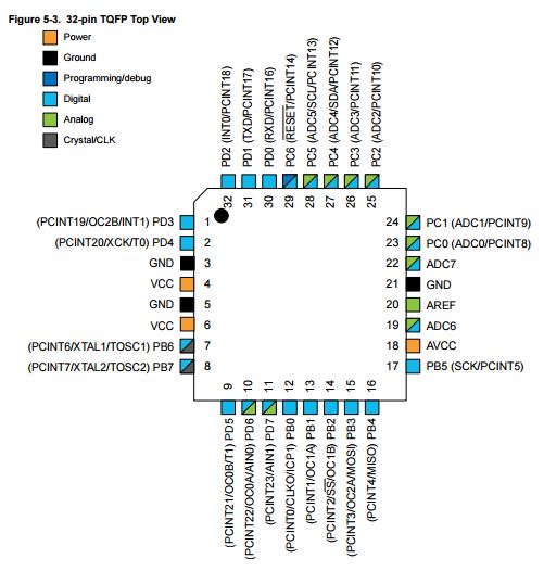
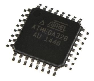
The microcontroller chosen for this project has been the Atmega328P AU, the specifications can be found in week 8
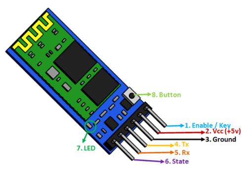
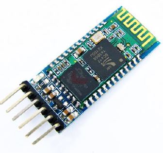
For the wireless communication I chose the bluetooth technology, by means of the module HC-05 used in the week 13
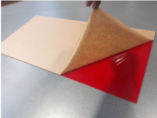
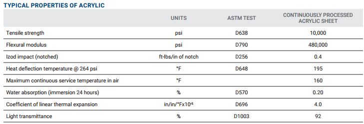
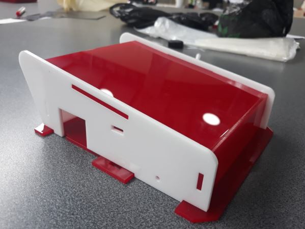
The choice of material to be used in the case of toys can be a bit ambiguous as it depends on the tastes and criteria of the people, currently there are toys made of plastic, metal or wood; Some of these materials are more welcome than others, everything depends on the purpose of the toy, functionalities and the reasons of the users. However, for the implementation of the prototype of the didactic toy proposed in this work, I chose 3 millimeter acrylic as the main material for both the robot housing and the communication board housing.
Design and production of electronic circuits
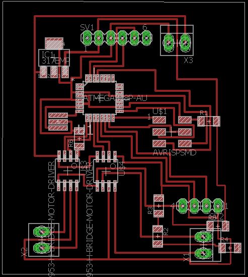
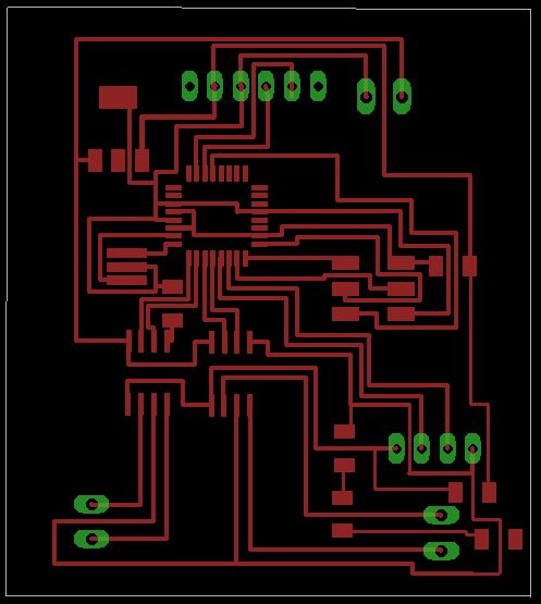
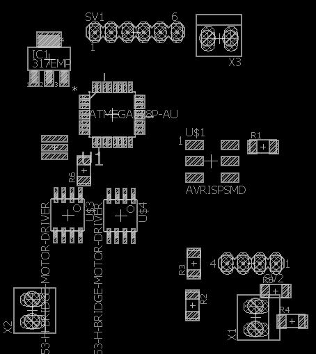
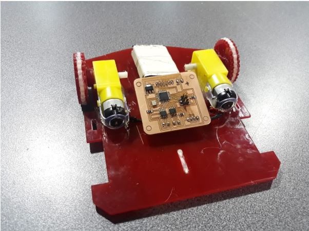
- Robot JEDPRO
Robot Diagram
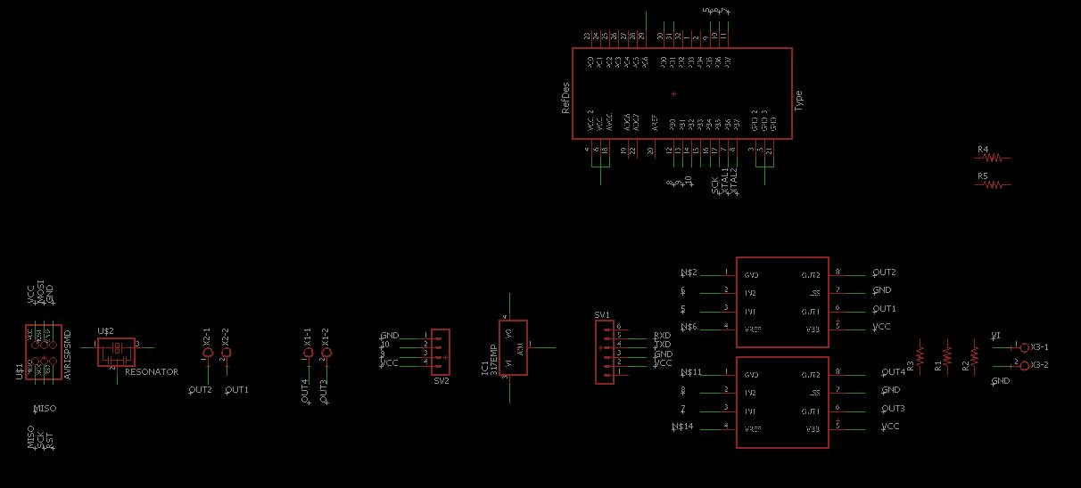
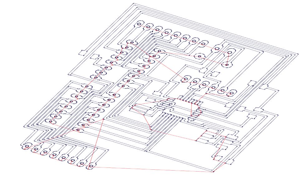
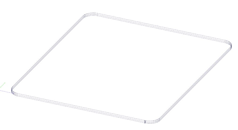
PCB board design
For the design of the electronic circuit board use the eagle software
Schematic
Board Design
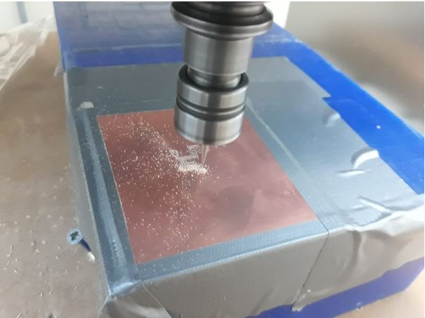
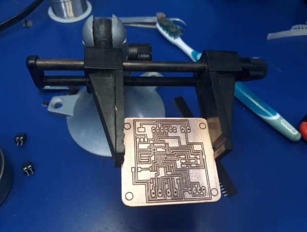
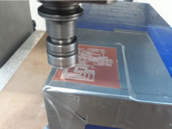
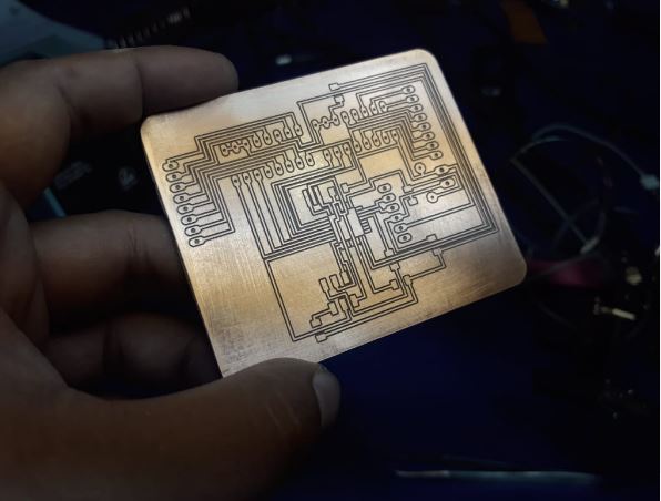
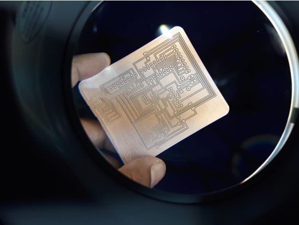
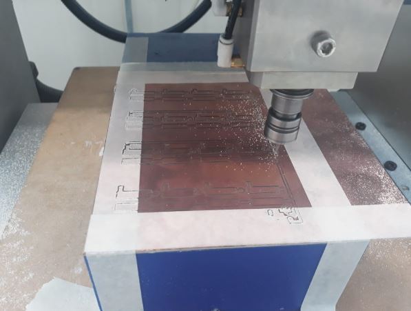
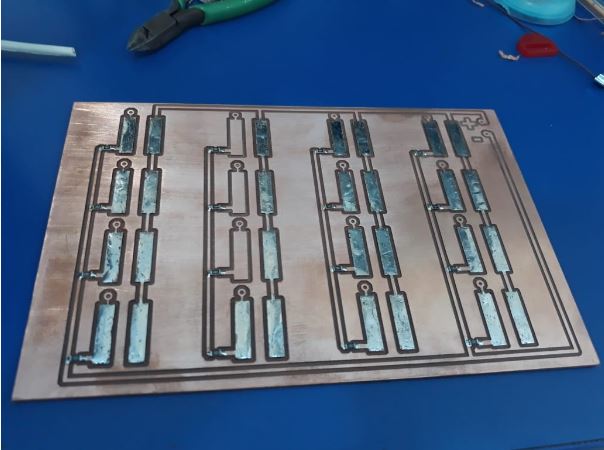
Fabrication and assembly
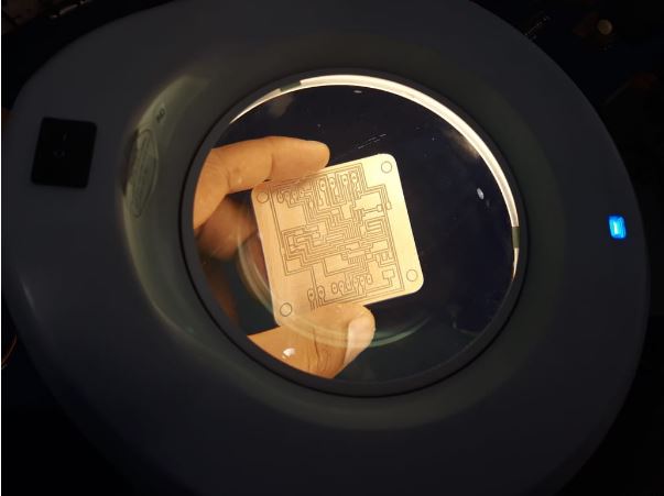
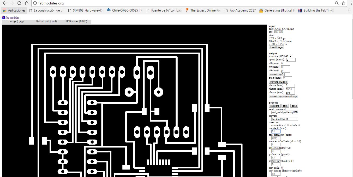
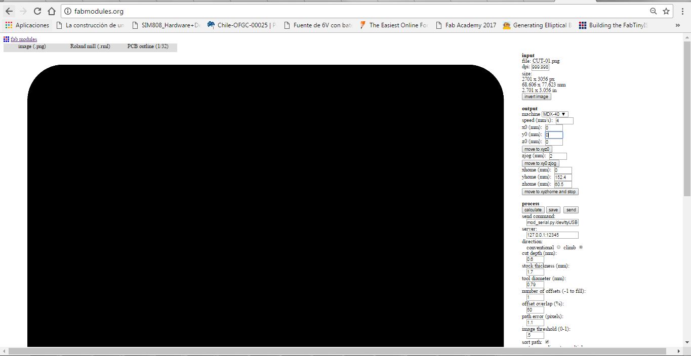
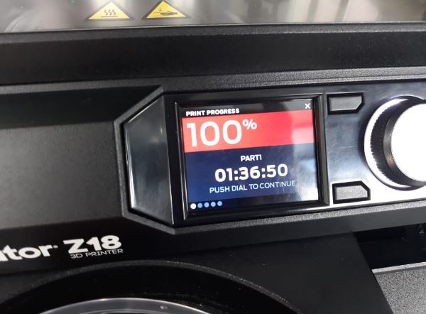
For the manufacture of the pcb board use the Roland MDX 540 CNC milling machine, the process can be seen in the assignment of week 4
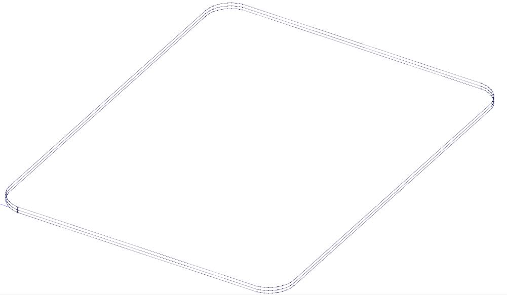
Cutting and machining file generation
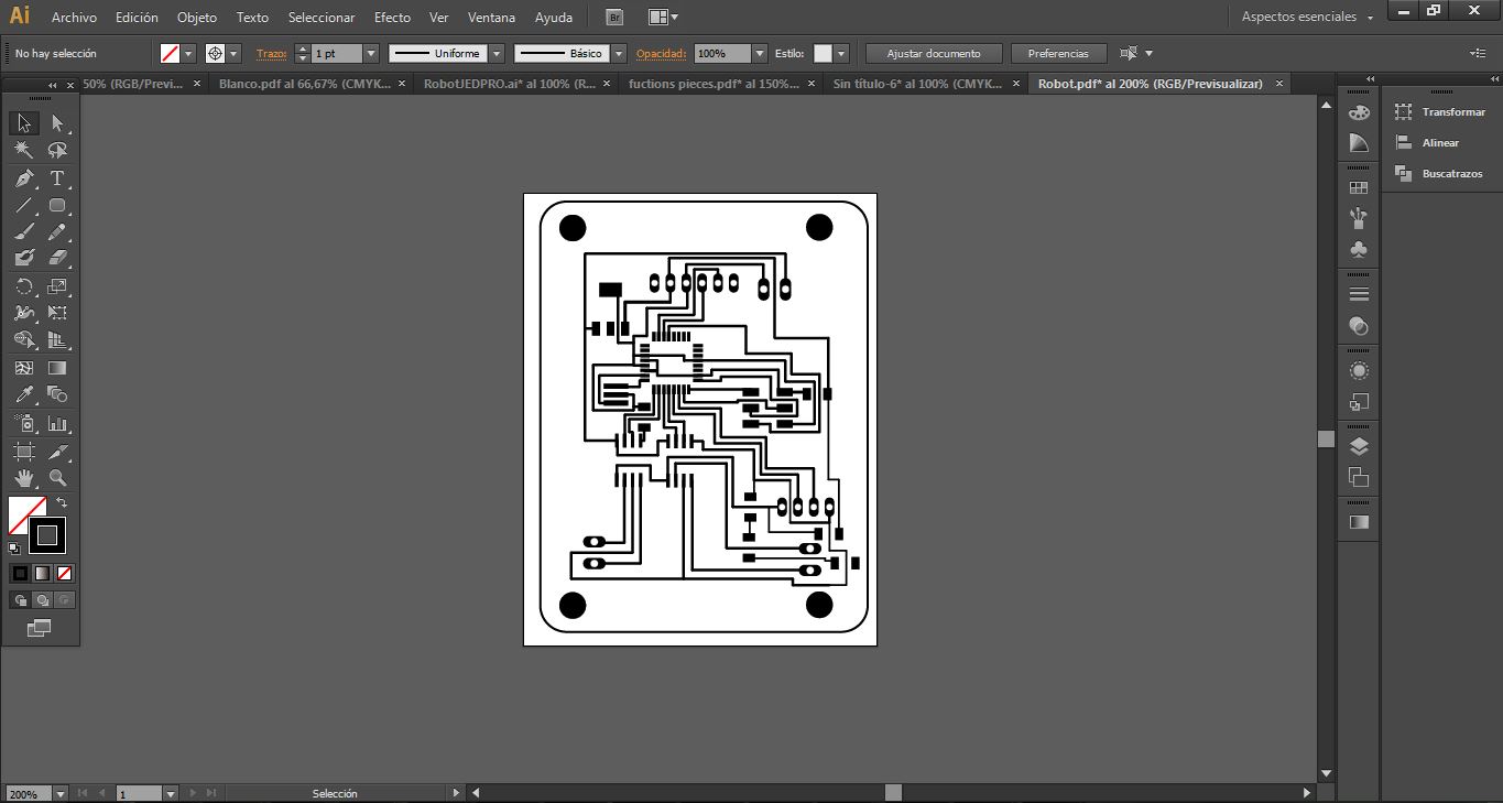
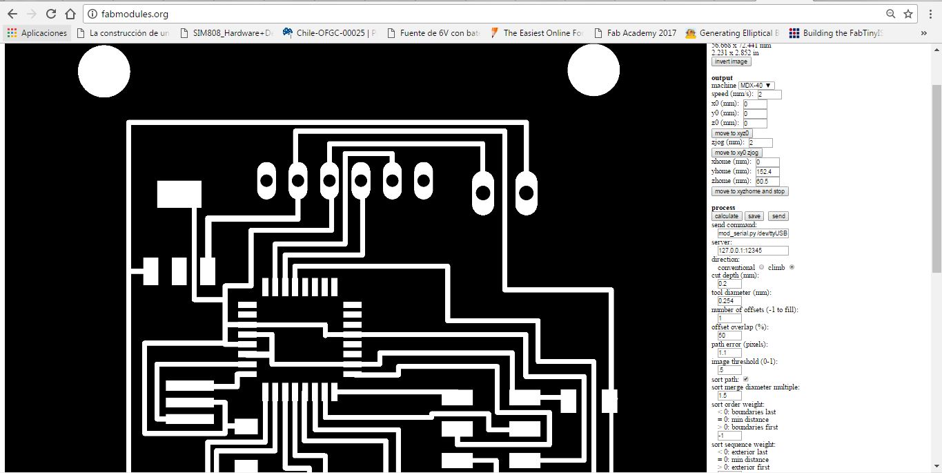
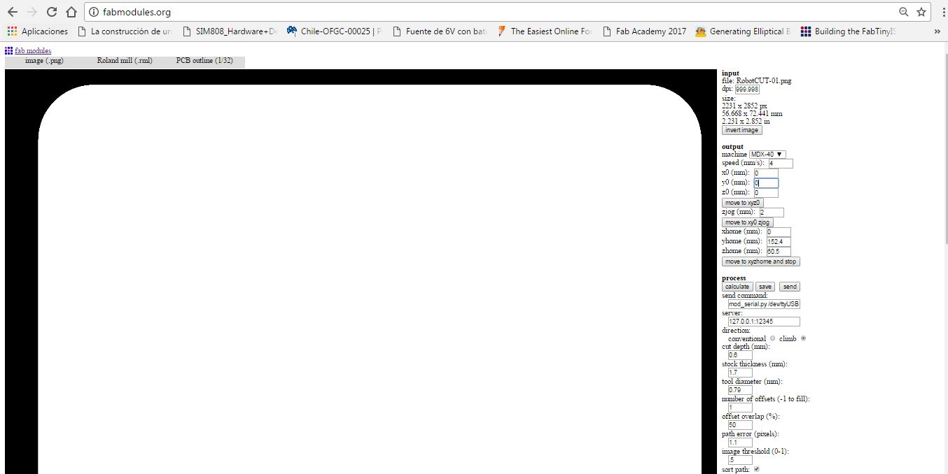
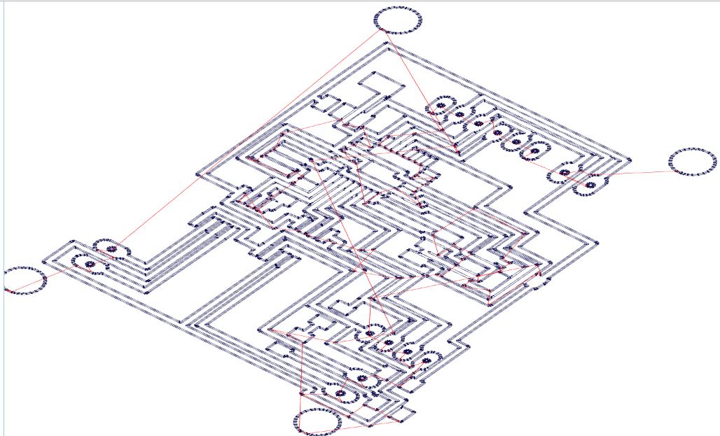
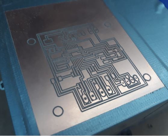
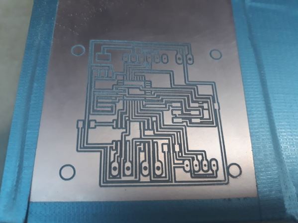
Fabrication
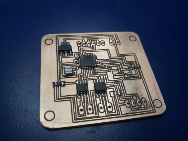
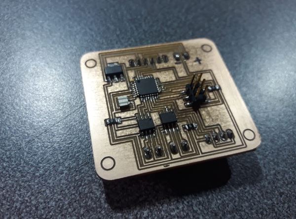
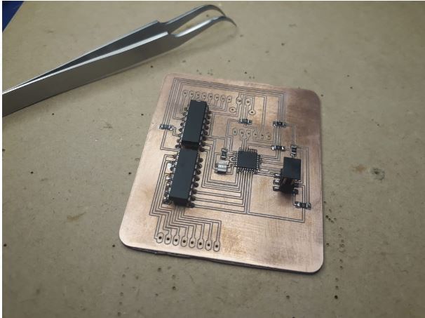
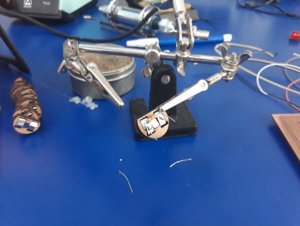
welding of electronic components
Components list
- 1 Atmega328 Microcontroller
- 2 Regulators 5V 2A
- 2 ISP pins 3 x 2
- 1 Resonator 20Mhz
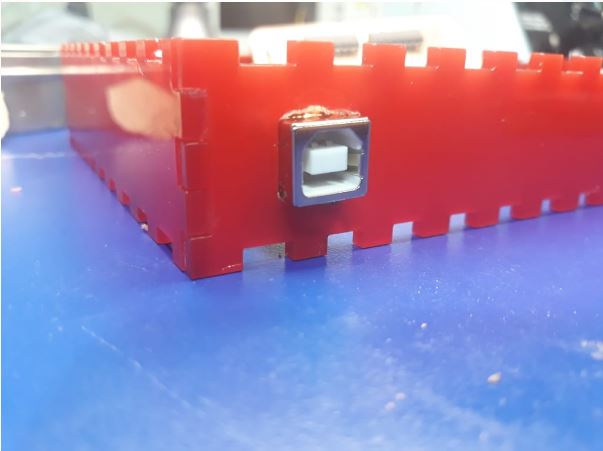
- 2 conector header
- 3 terminal pins
- 6 resistors 0 0hm
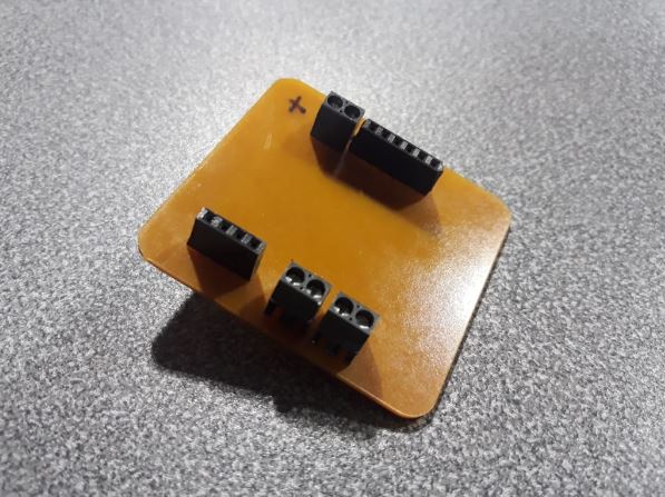
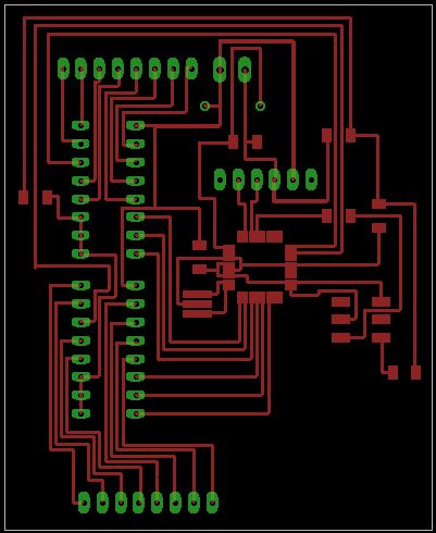
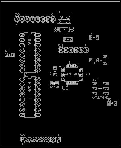
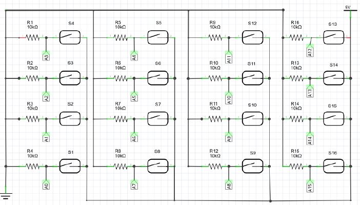
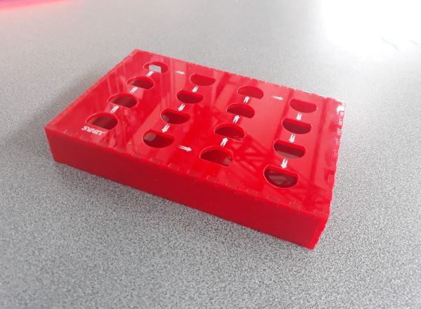
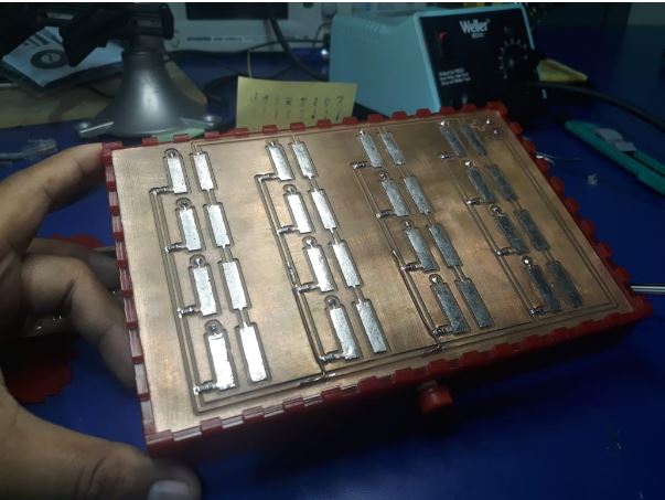
- Programming interface
Programming Interface diagram
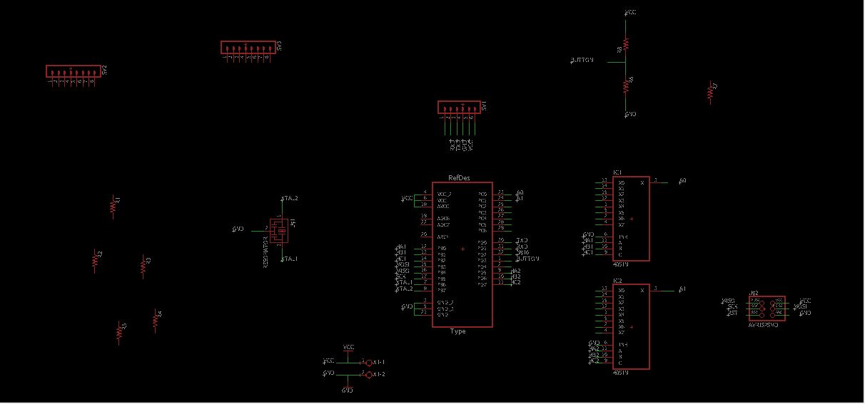
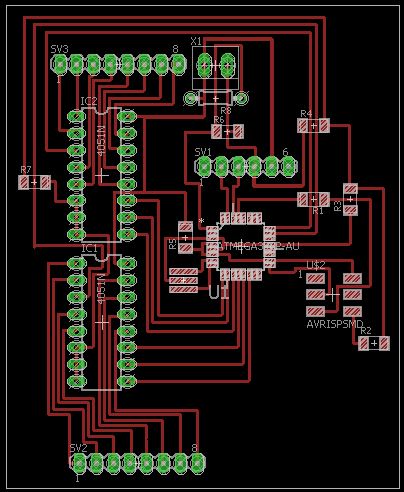
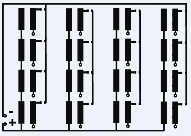
PCB board design
For the design of the electronic circuit board use the eagle software
Schematic
Board Design
Fabrication and assembly
For the manufacture of the pcb board use the Roland MDX 540 CNC milling machine, the process can be seen in the assignment of week 4
Cutting and machining file generation
Fabrication
welding of electronic components
Components list
- 1 Atmega328 Microcontroller
- 2 4051 Multiplexer
- 2 ISP pins 3 x 2
- 1 Resonator 20Mhz
- 2 conector header
- 3 terminal pins
- 5resistors 0 0hm
- Push Button
Circuit for reading analog inputs

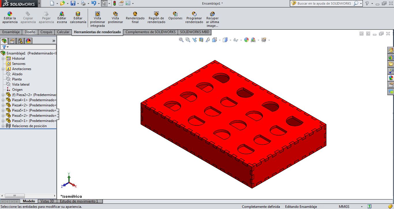
2D and 3D Design
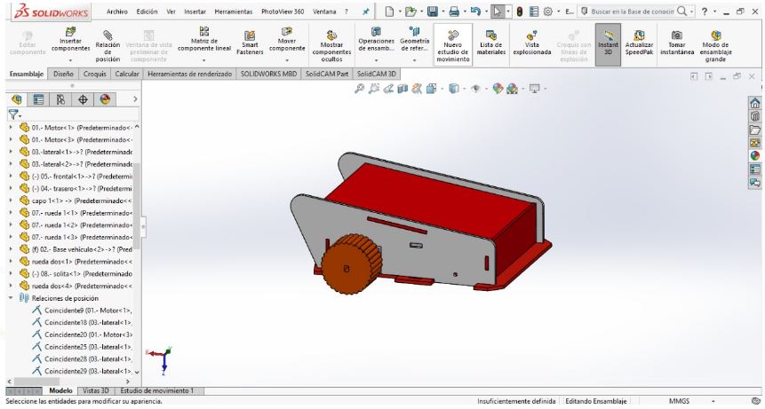
For the design and 3D modeling, solidworks software was used, the design was based on those learned in week 2
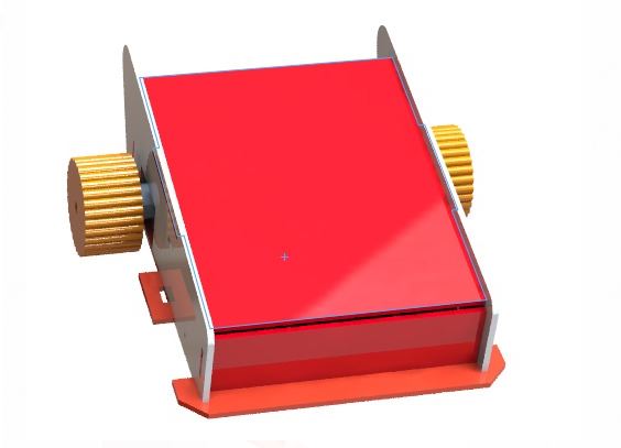
Robot JEDPRO
Programming interface
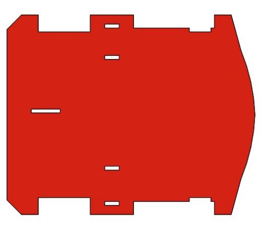
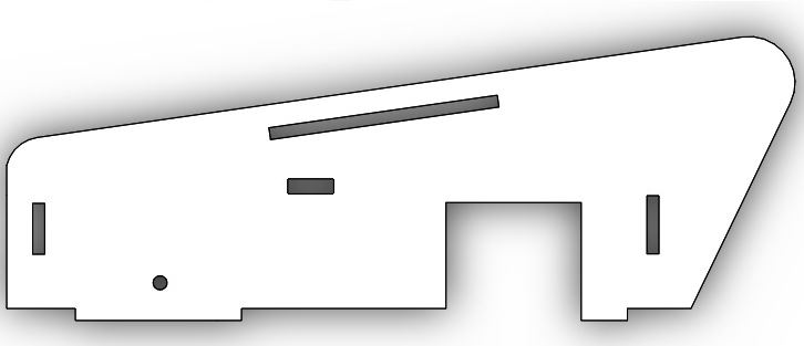
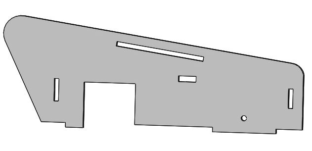
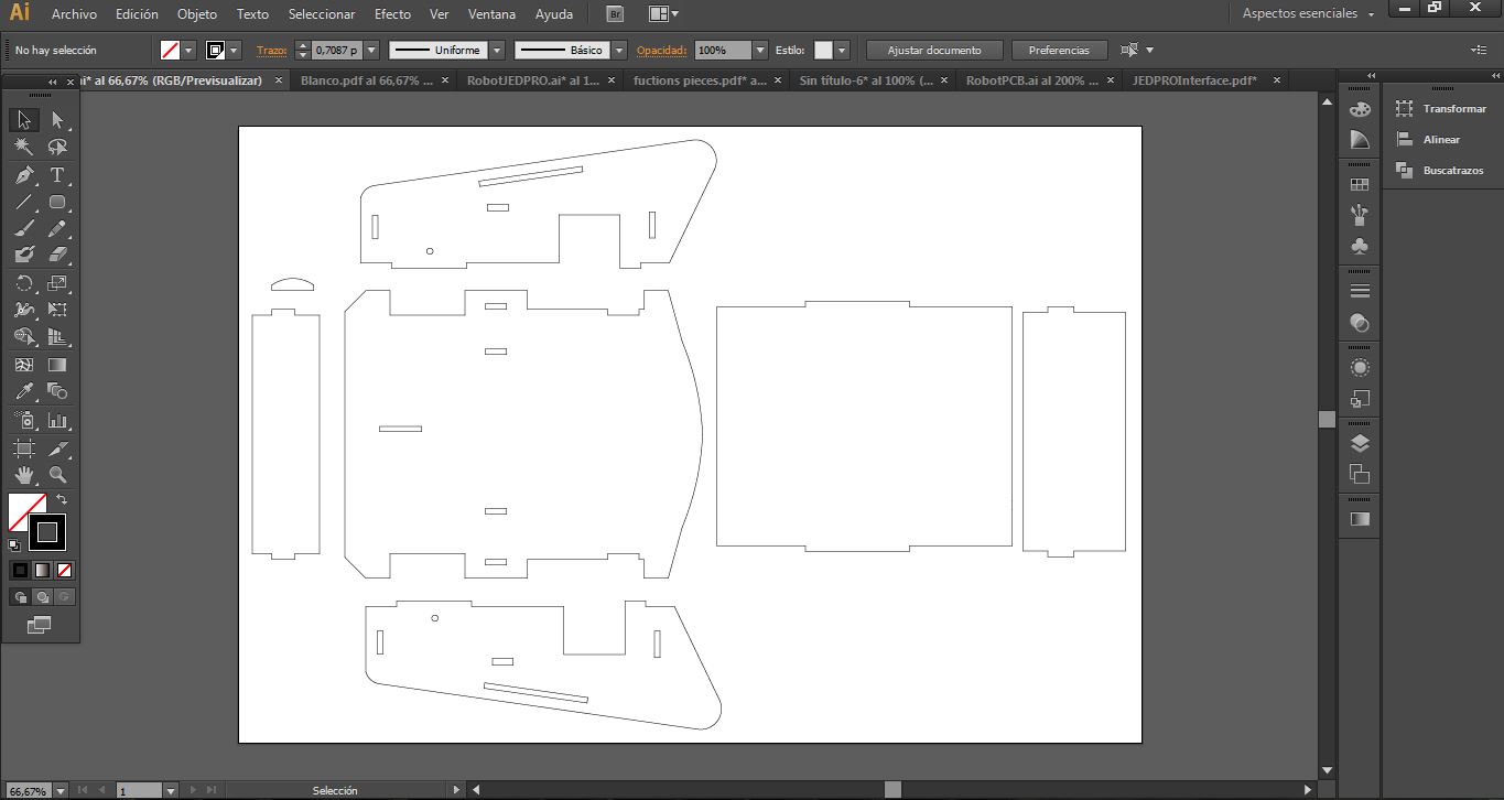
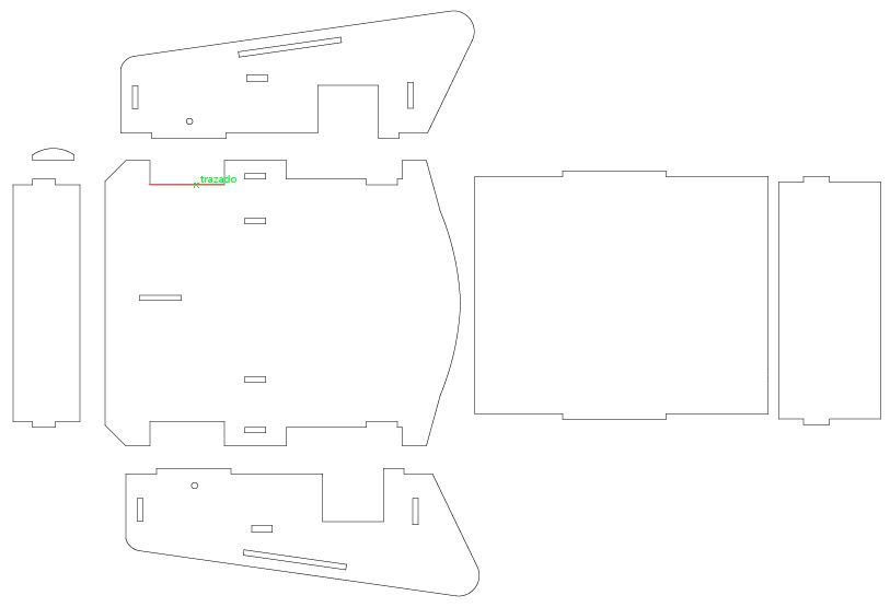
Laser cutting of parts
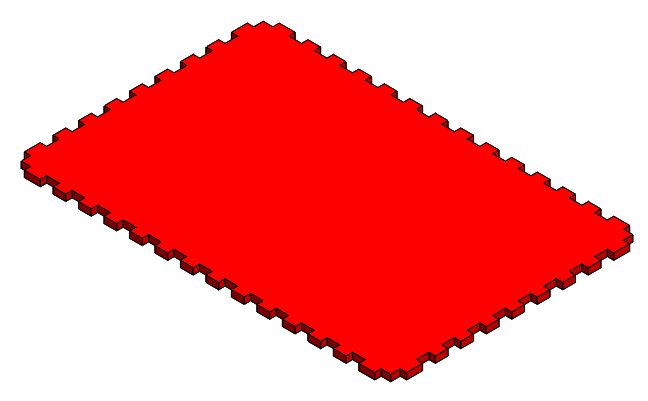
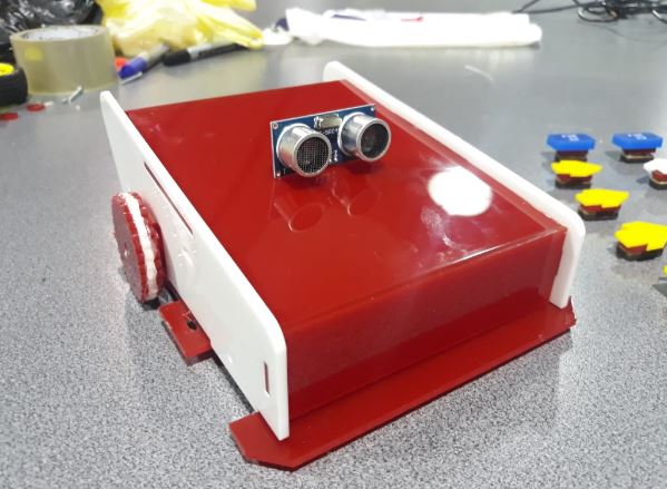
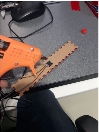
For the manufacture of the Robot case and the interface, laser cutting and engraving was used using the ZING LASER machine, more information about the laser cutting and engraving process can be found in week 3
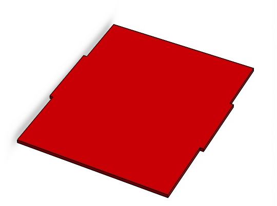
Case Robot
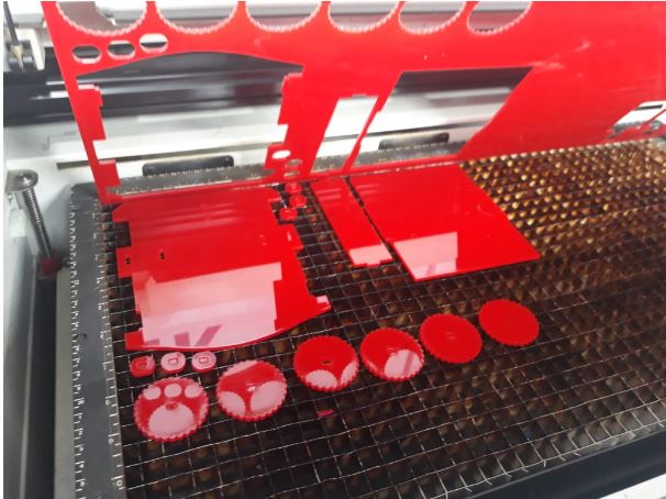
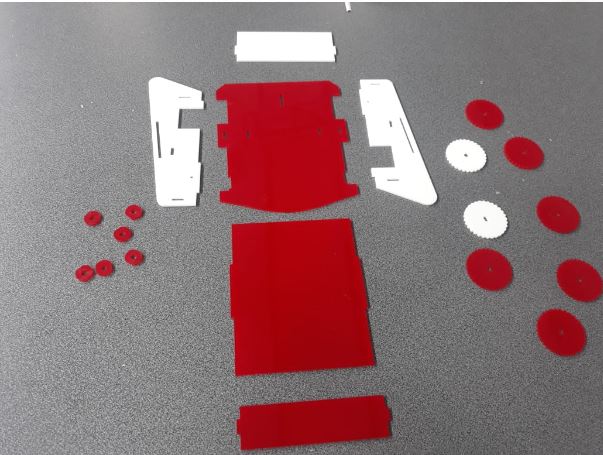
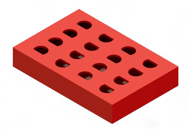
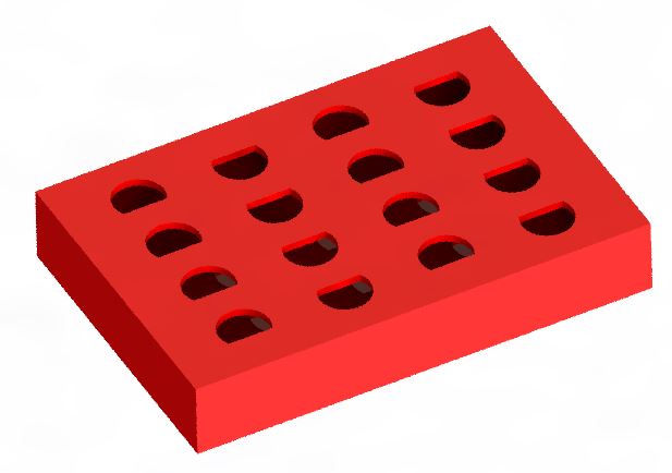
Programming interface
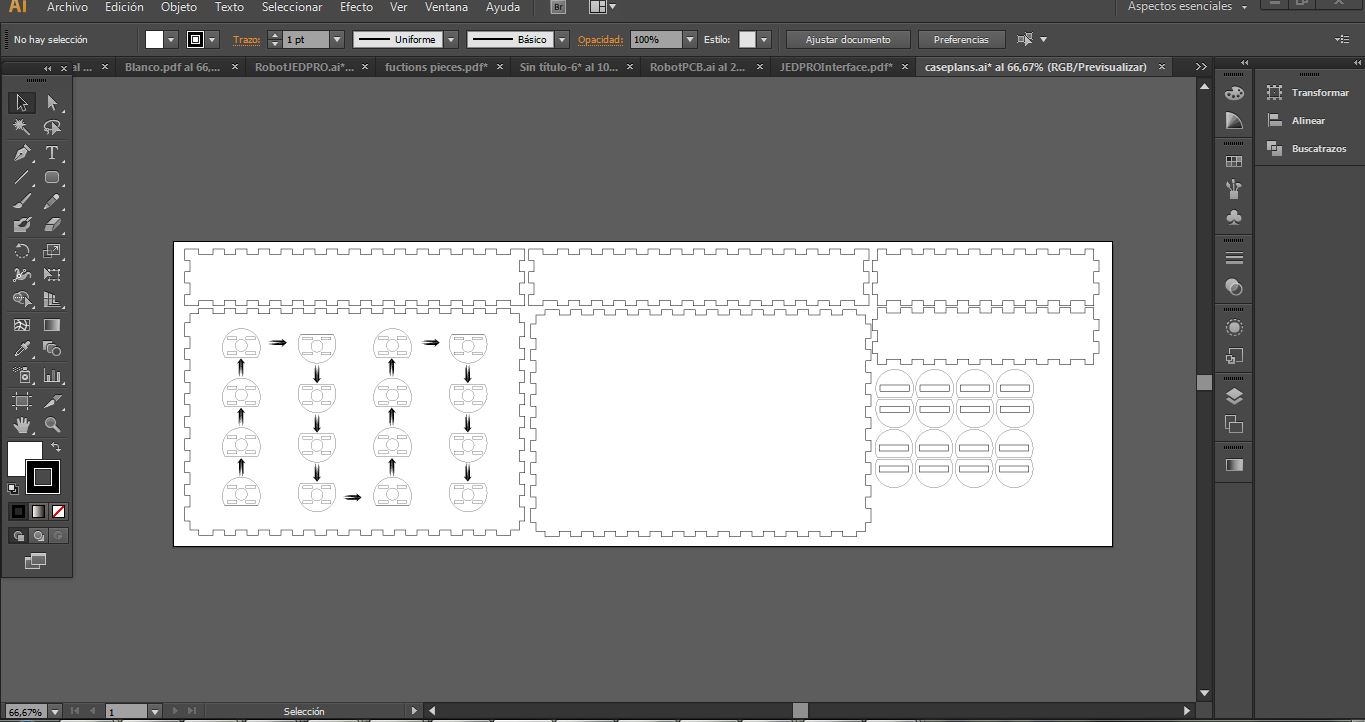
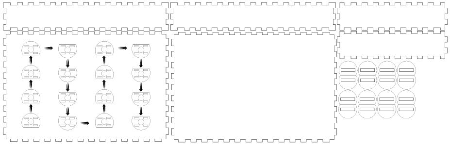
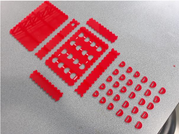
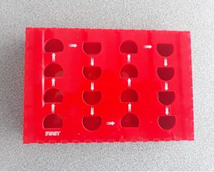
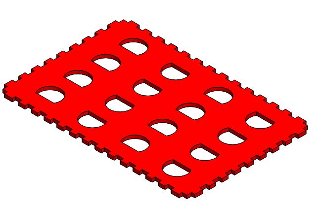
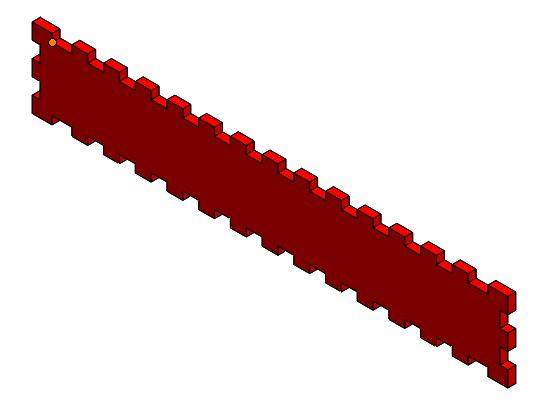
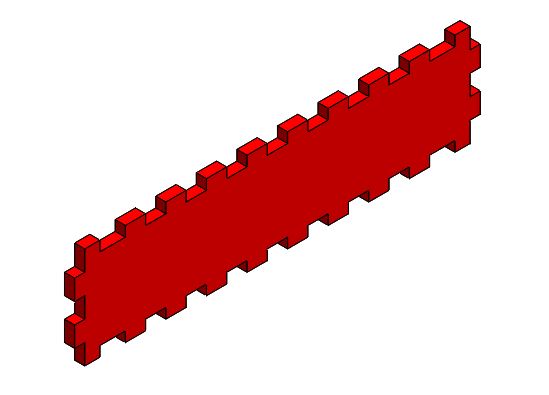
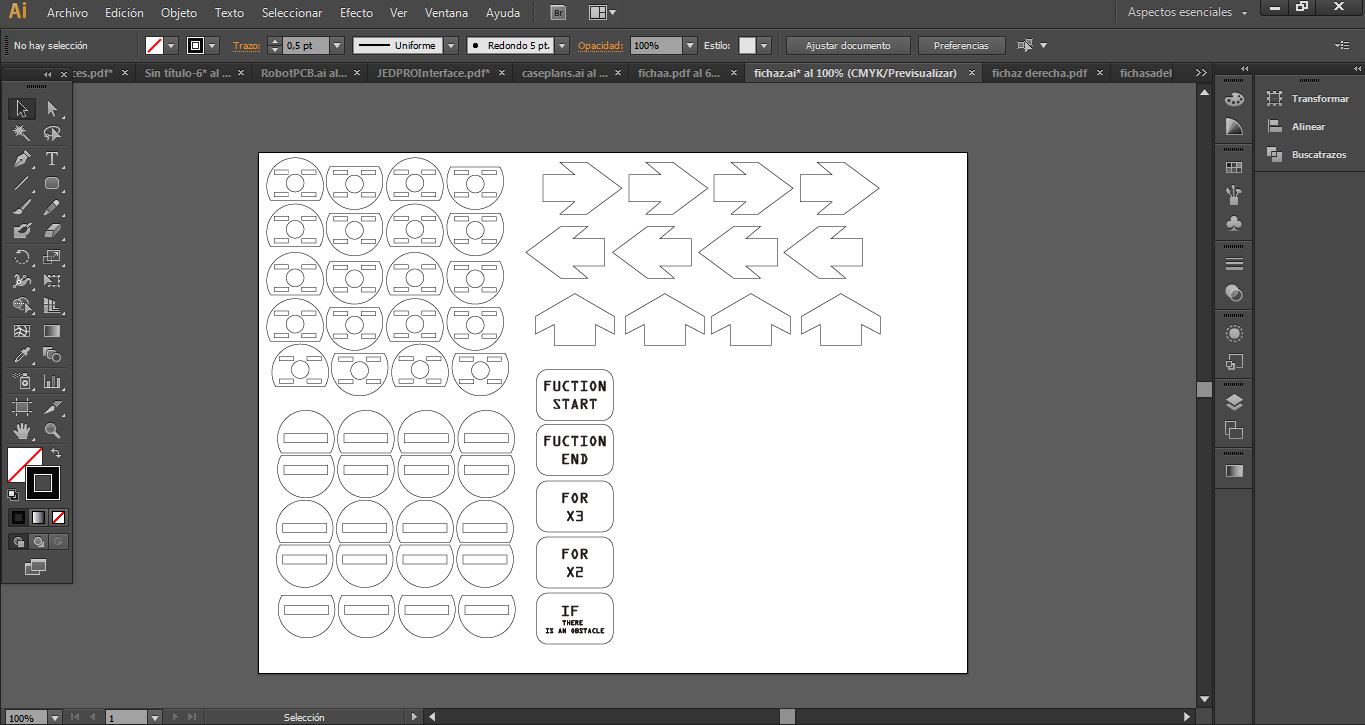
Block instructions
3D Printing
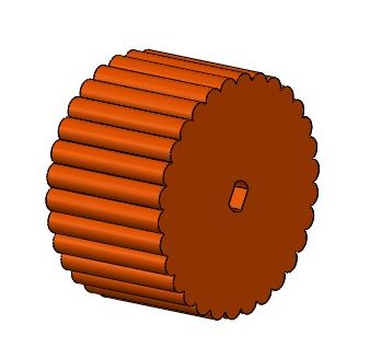
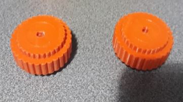
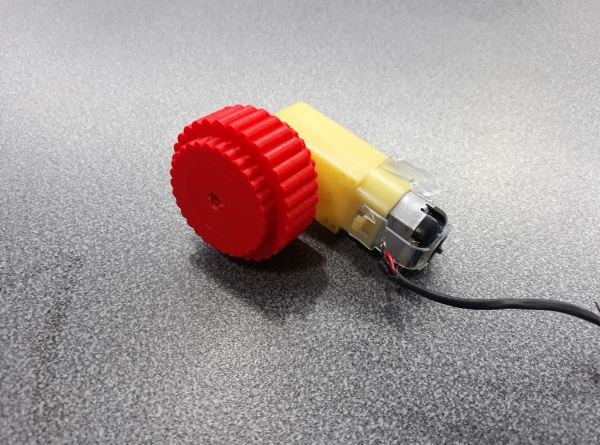
I have manufactured the robot wheels in 3D printing - week 5
Assembly
 />
/>
Programming
Robot JEDPRO
 Main.ino
const int trigger = 3;
const int echo = 4;
const int MOTOR1_ADELANTE = 5;
const int MOTOR1_ATRAS = 6;
const int MOTOR2_ADELANTE = 10;          MOTOR2
const int MOTOR2_ATRAS = 11;
//const int BATERIA=0;
float distance = 5;
const int EncoderIzquierdo = A0;
const int EncoderDerecho = A1;
//**********************************************************************************************
char vectorPrincipal[16];
char funcion[16];
char funcion2[16];
char funcion3[16];
int i, j, k, z, l, x, m, n;
char dato;
int var=0;
int var2=0;
int var3=0;
int pos;
int pos2;
int pos3;
char iniciar;
//////////////////////////////////////////////////////////////////////////////////////////////////
void setup() {
  Serial.begin(9600);
  pinMode(trigger, OUTPUT);
  pinMode(echo, INPUT);
  pinMode(MOTOR1_ADELANTE, OUTPUT);
  pinMode(MOTOR2_ADELANTE, OUTPUT);
  pinMode(MOTOR1_ATRAS, OUTPUT);
  pinMode(MOTOR2_ATRAS, OUTPUT);
  delay(2000);
}


void loop() {
while(true){

  if (Serial.available() > 0) {
    char letra = Serial.read();
    if (letra == 'A' || letra == 'B' || letra == 'C' || letra == 'D' || letra == 'E' || letra == 'F' || letra == '{' || letra == '}' ) {
      vectorPrincipal[i] = letra;
      delay(100);
      i++;
      //Serial.println(i);
    }
    else {
      if (letra == '0')
      {
        iniciar = '1';
      }

    }

  }
  //******************************************************************************************************************************************************
  if (iniciar == '1') {
    LeerCiclo3();
    LeerCiclo2();
    Obstaculo();
    for (z = 0; z < i; z++) {
      if (vectorPrincipal[z] != 'D' && vectorPrincipal[z] != 'E' && vectorPrincipal[z] != 'F' ) {
        dato = vectorPrincipal[z];
        delay(10);
        instrucciones();
            var=0; var2=0;var3=0;
      }

      else
      { //CASO CONTRARIO
        if (vectorPrincipal[z] == 'E') {
          for (l = 0; l < 3; l++) {
            for (x = 0; x < k; x++) {
              dato = funcion[x];
              instrucciones();
            var=0; var2=0;var3=0;
              delay(200);
            }
          }
        }

        else {
          if (vectorPrincipal[z] == 'D') {
            for (l = 0; l < 2; l++) {
              for (x = 0; x < m; x++) {
                dato = funcion2[x];
                instrucciones();
                var=0; var2=0;var3=0;
                delay(200);
              }
            }
          }
          else
          {
            if (vectorPrincipal[z] == 'F') {

              while (distance > 0.30) {
             //   dato = 'A';
               // instrucciones();
               delay(50);
               digitalWrite(MOTOR1_ADELANTE,HIGH);
               digitalWrite(MOTOR2_ATRAS,HIGH);
               digitalWrite(MOTOR1_ATRAS, LOW);
               digitalWrite(MOTOR2_ADELANTE, LOW);
               delay(100);
               digitalWrite(MOTOR1_ADELANTE, LOW);
               digitalWrite(MOTOR1_ATRAS, LOW);
               digitalWrite(MOTOR2_ADELANTE, LOW);
               digitalWrite(MOTOR2_ATRAS, LOW);
                digitalWrite(trigger, LOW);
                delayMicroseconds(5);
                digitalWrite(trigger, HIGH);
                delayMicroseconds(10);
                digitalWrite(trigger, LOW);
                distance = pulseIn(echo, HIGH);
                distance = distance * 0.0001657;
               // var=0; var2=0;var3=0;
            };
              for (x = 0; x < n; x++) {
                dato = funcion3[x];
                instrucciones();
                var=0; var2=0;var3=0;
                delay(200);

              };
            }

          }
        }

      }
    }

    i = 0;
    k = 0;
    m = 0;
    n = 0;
    distance = 5;
    iniciar = '0';


  }
}
}
 functions.ino


void LeerCiclo3 ()
{
  for (j = 0; j <= i; j++) {
    if (vectorPrincipal[j] == 'E' && vectorPrincipal[j + 1] == '{' )  {
    {
      pos = j + 1;
      while (vectorPrincipal[pos] != '}') {
        funcion[k] = vectorPrincipal[pos];
        delay(10);
        vectorPrincipal[pos] = ' ';
        delay(10);
        pos++;
        k++;
      }
    }
  }
}
//*****************************************************************************************************************************


void LeerCiclo2 ()
{
  for (j = 0; j <= i; j++) {
    if (vectorPrincipal[j] == 'D' && vectorPrincipal[j + 1] == '{' )
    {
      pos2 = j + 1;
      while (vectorPrincipal[pos2] != '}') {
        funcion2[m] = vectorPrincipal[pos2];
        delay(10);
        vectorPrincipal[pos2] = ' ';
        delay(10);
        pos2++;
        m++;
      }
    }
  }
}
//*****************************************************************************************************************************

void Obstaculo ()
{
  for (j = 0; j <= i; j++) {
    if (vectorPrincipal[j] == 'G' && vectorPrincipal[j + 1] == '{' )
    {
      pos3 = j + 1;
      while (vectorPrincipal[pos3] != '}') {
        funcion3[n] = vectorPrincipal[pos3];
        delay(10);
        vectorPrincipal[pos3] = ' ';
        delay(10);
        pos3++;
        n++;
      }
    }
  }
}
//********************************************************************************************************************************


//*****************************************************************************************************************************
void instrucciones() {

  switch (dato) {

    case 'A':
     delay(200);
    while(var<200){
  delayMicroseconds(1000);
  digitalWrite(MOTOR2_ATRAS,HIGH);
  digitalWrite(MOTOR1_ADELANTE,HIGH);
  digitalWrite(MOTOR1_ATRAS, LOW);
  digitalWrite(MOTOR2_ADELANTE, LOW);

  delayMicroseconds(3500);
  digitalWrite(MOTOR1_ADELANTE, LOW);
  digitalWrite(MOTOR1_ATRAS, LOW);
  digitalWrite(MOTOR2_ADELANTE, LOW);
  digitalWrite(MOTOR2_ATRAS, LOW);
  var++;
  Serial.println(var);
  delayMicroseconds(100);
    }
      break;

    case 'B':
    delay(200);
      while(var2<130){
delayMicroseconds(300);
digitalWrite(MOTOR2_ATRAS,HIGH);
  digitalWrite(MOTOR1_ATRAS, HIGH);
  digitalWrite(MOTOR1_ADELANTE,LOW);
  digitalWrite(MOTOR2_ADELANTE, LOW);

delayMicroseconds(2500);
  digitalWrite(MOTOR1_ADELANTE, LOW);
  digitalWrite(MOTOR1_ATRAS, LOW);
  digitalWrite(MOTOR2_ADELANTE, LOW);
  digitalWrite(MOTOR2_ATRAS, LOW);
  var2++;
  Serial.println(var2);
  delayMicroseconds(100);
    }
      break;

    case 'C':
    delay(100);
      while(var3<130){
  delayMicroseconds(300);
  digitalWrite(MOTOR1_ADELANTE,HIGH);
  digitalWrite(MOTOR2_ADELANTE, HIGH);
  digitalWrite(MOTOR1_ATRAS, LOW);
  digitalWrite(MOTOR2_ATRAS,LOW);
  delayMicroseconds(2500);
  digitalWrite(MOTOR1_ADELANTE, LOW);
  digitalWrite(MOTOR1_ATRAS, LOW);
  digitalWrite(MOTOR2_ADELANTE, LOW);
  digitalWrite(MOTOR2_ATRAS, LOW);
  var3++;
  Serial.println(var3);
  delayMicroseconds(100);
    }
      break;


    default:
      digitalWrite(MOTOR1_ADELANTE, LOW);
  digitalWrite(MOTOR1_ATRAS, LOW);
  digitalWrite(MOTOR2_ADELANTE, LOW);
  digitalWrite(MOTOR2_ATRAS, LOW);
      break;
  }
}
Programming interface
 interface.ino
int estadoBoton;
const int tiempoAntirebote = 20;
int estadoBotonAnterior;
int lecturas[16];
int rango = 15;
const int seleccion1 [] = {5, 6, 7};
const int seleccion2 [] = {8, 9, 10};
const int analogPin2 = A0;
const int analogPin = A1;
const int Boton = 3;

/
void setup ( ) {
  Serial.begin(9600);
  for (int bit = 0; bit < 3; bit++) {
    pinMode(seleccion1[ bit ], OUTPUT);
    pinMode(seleccion2[ bit ], OUTPUT);
  }
  pinMode(Boton, INPUT);

}
////////////////////////////////////////////////////////////////////////////////////////////////////


/////////////////////////////////////////////METODOS////////////////////////////////////////////////

int mux1( int channel) {
  for (int bit = 0; bit < 3; bit++) {
    int pin = seleccion1 [ bit ];
    int isBitSet = bitRead(channel, bit);
    digitalWrite(pin, isBitSet);
    delay(30);
  }
  return analogRead(analogPin);
}

int mux2( int channel2) {
  for (int bit = 0; bit < 3; bit++) {
    int pin2 = seleccion2 [ bit ];
    int isBitSet2 = bitRead(channel2, bit);
    digitalWrite(pin2, isBitSet2);
    delay(30);

  }
  return analogRead(analogPin2);
}


boolean antirrebote(int pin)
{
  int contador = 0;
  boolean estado;
  boolean estadoAnterior;
  do {
    estado = digitalRead(pin);
    if (estado != estadoAnterior) {
      contador = 0;
      estadoAnterior = estado;
    }
    else {
      contador++;
    }
    delay(1);
  } while (contador < tiempoAntirebote);
  return estado;
}

void LeerEntradas() {
  for (int i = 0; i < 8; i++) {
    int value = mux1(i);
    lecturas[i] = value;
   //Serial.println(lecturas[i]);
  }
  for (int j = 8; j < 16; j++) {
    int value2 = mux2(j);
    lecturas[j] = value2;
  // Serial.println(lecturas[j]);
  }
}

void Instrucciones(int i) {

  if (lecturas[i] > (980 - rango) && lecturas[i] < (1000 + rango)) {
    Serial.println('A');
    delay(100);
  }

  if (lecturas[i] > (639 - rango) && lecturas[i] < (710 + rango)) {
    Serial.println('B');
    delay(100);
  }

  if (lecturas[i] > (416 - rango) && lecturas[i] < ( 520 + rango )) {
    Serial.println('C');
    delay(100);
  }

//  if (lecturas[i] > (89 - rango) && lecturas[i] < (89 + rango)) {
//
//    Serial.println('E');
//    delay(100);
//  }
//
//  if (lecturas[i] > (510 - rango) && lecturas[i] < (510 + rango)) {
//    Serial.println('D');
//    delay(100);
//  }
//
//  if (lecturas[i] > (837-rango) && lecturas[i] < (837 + rango)) {
//    Serial.println('F');
//    delay(100);
//  }
//
//  if (lecturas[i] > (175 - rango) && lecturas[i] < ( 175 + rango)) {
//    Serial.println('{');
//    delay(100);
//  }
//
//  if (lecturas[i] > (764 - rango) && lecturas[i] < (764 + rango)) {
//    Serial.println('}');
//    delay(100);
//  }
  }
//////////////////////////////////////////////////////////////////////////////////////////////

void loop ( ) {
  estadoBoton = digitalRead(Boton);

  if (estadoBoton != estadoBotonAnterior) {

    if (antirrebote(Boton)) {
      LeerEntradas();


      for ( int i = 0; i < 17; i++) {
        if (lecturas[i] > 10) {
          //Serial.println(lecturas[i]);
           Instrucciones(i);

        }
        else {        // caso contrario
          Serial.println('0');
          delay(100);

          break;
        }

      }


    }

  }
  estadoBotonAnterior = estadoBoton;
  delay(30);
}
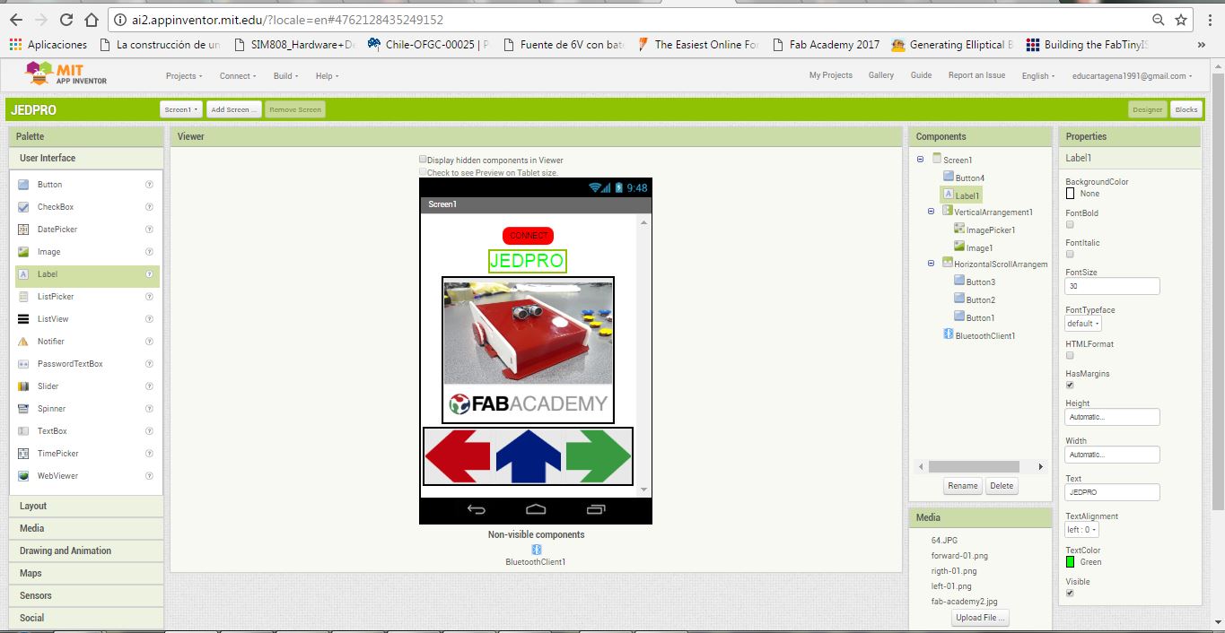
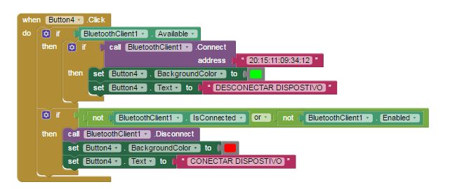
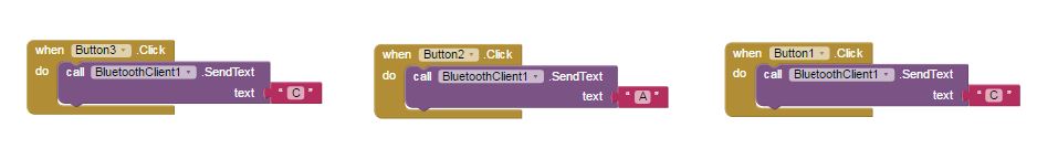
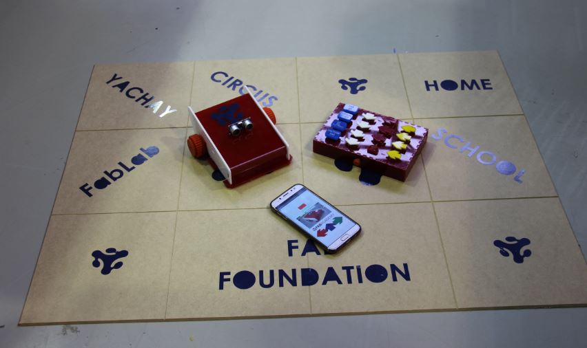
Mobile application design
The application was designed on the APP INVENTOR platform, see week 12
JEDPRO Scenary
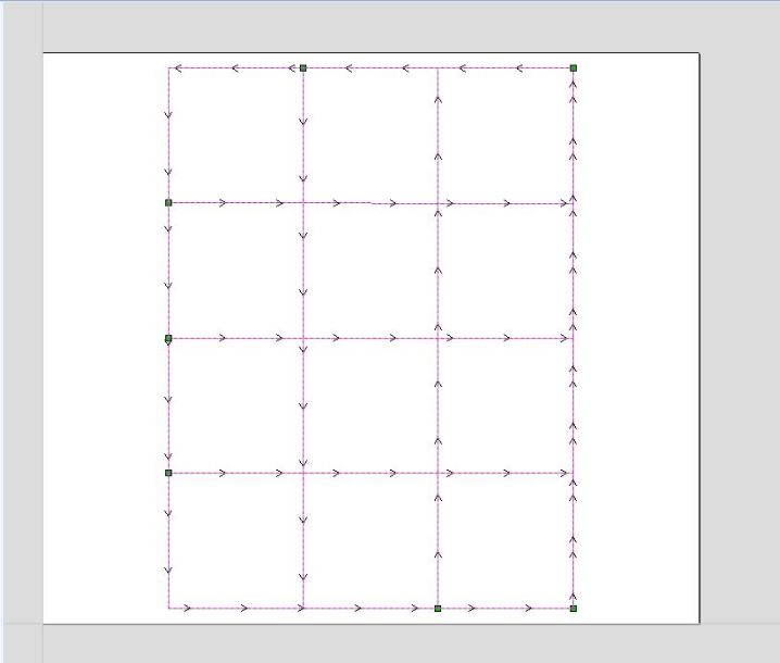
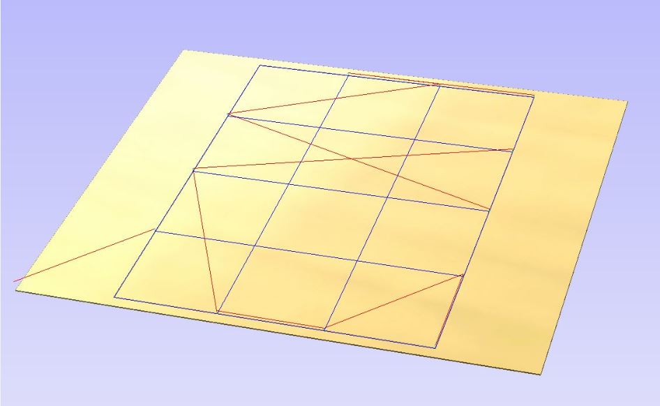
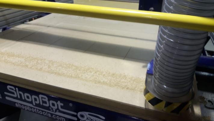
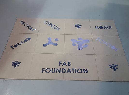
The stage or training track of JEDPRO I have manufactured in the CNC Shopbot milling machine, information about this machine you can find it in the week 7
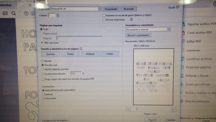
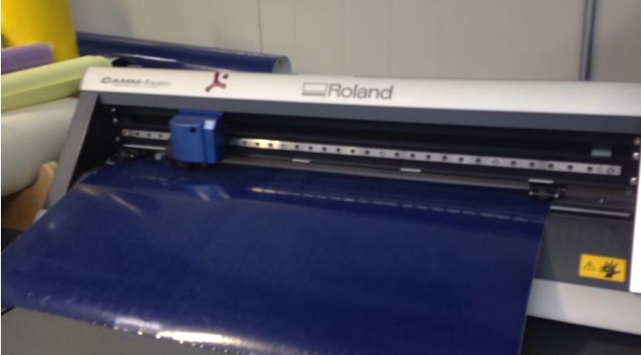
, also use vinyl cutting for decoration, see week 3.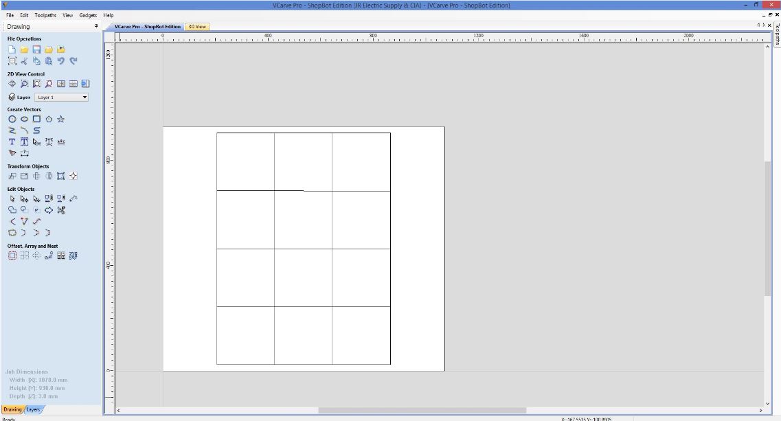
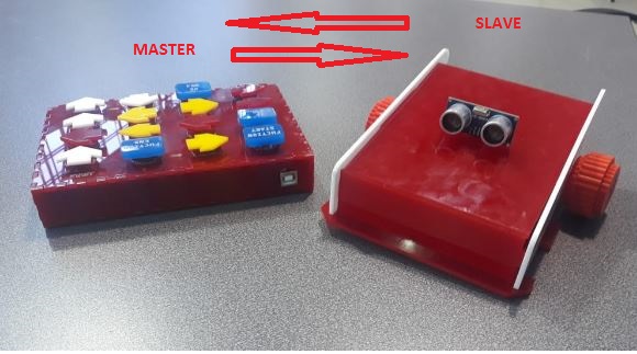
Comminication
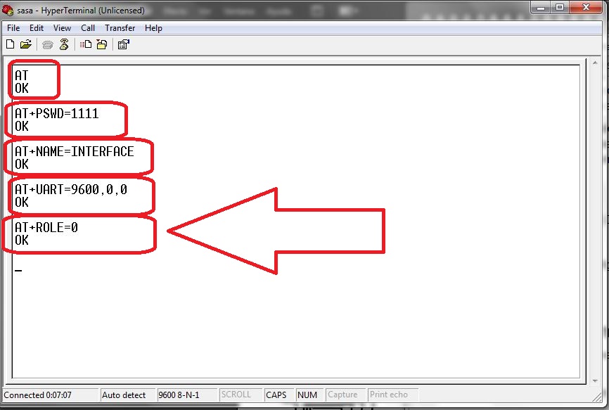
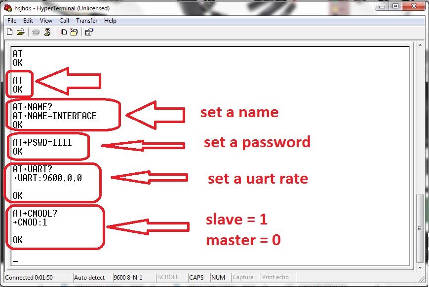
For the communication between the programming interface and the robot the bluetooth technology was used, using the modules hc-05, for this a module was configured as a slave and the other as a master, the configuration of the bluetooth modules you can see it in the week 13
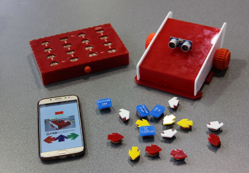
Final prototype
How will I complete the remaining tasks in time?
In the last weeks we have intensified the work with the team supporting each other according to the strength of each one to accelerate the work and be able to complete all the tasks on time
What have you worked?
Until this week I have an 85 percent of the project working correctly, among which we can highlight the electronic circuits, 2d and 3d designs, programming and configuration of wireless communication.
What has not happened?
I still need to strengthen the mobile application, for the connection and control of the robot as an additional function
What questions need to be resolved?
- How complicated will it be for children to program the robot?
- What are the appropriate ages to teach how to program children?
What have you learned?
During the program I have obtained many knowledge and experiences on the different topics of digital manufacturing and prototyping, however I think the most important thing was the team work and friendship that was formed during the course of the program.
Intellectual property issues also seemed very important to me.

DOWNLOADS
- File 1: Case Files
- File 2: Programming
- File 3: Robot Files
- File 4: Wheels Files
- File 5: 3D Files Robot
- File 6: 3D Files Interface
- File 7: Eagle files Robot
- File 8: Eagle files Interface
- File 9: App Inventor - JEDPRO