Computer Aided Design
Wednesday January 31, 2018
Preamble

AS part of this week's pre-lecture activities we interviewed another "fabber" to get to know their background and a bit about their journey through the Fab life. Fabber is short for 'fabricationist' which, (not a word), is long for fabricator. My fabber interviewee was Instructor and Fab Foundation member Francisco Sanchez from Barcelona (pictured right).
*** The following interview is paraphrased as a result of my terrible transcription techniques. After all, I'm an engineer not a journalist! ***
Francisco attended FabAcademy in 2013 with little knowledge in digital fabrication. You can check out his rather entertaining journey on the archive! He was a Civil Engineer working in environmental certification. He gained his passion for the Fab Lab movement in a rather interesting way.
Francisco: So I was working on a highrise project where they needed 100 points [of environmental certification]... in enclosed spaces where there's more than eight people we had to install a sensor for CO2. We needed 10 units, for one [environmental] point. The idea is that at a certain concentration of CO2 a warning would activate to remind patrons to open a window or take ventilation measures.
Existing solutions to this costed around 500 euros each, and they required 10 units. That was an expensive way to gain one 'environmental point' of which they needed 100 total. After poking around on the interwebs he found an open-source solution someone had posted made using an Arduino for around 35 euros each. Francisco:"I didn't even know what an Arduino WAS at that point."
He got together with his work partner and they decided to try it out. "So we bought the kit and soldered it all together and.. It worked!" They took it to the certification agency to ask if they would be allowed to use it in the building design.
"Surprisingly, they approved it! They looked at the data sheets for the sensors and said it was accepted."
That was just the start of Francisco's adventure as a fabber. "After that I looked all around the internet for more solutions just like this... We had just created an entire solution for the cost of one single unit. I wanted to see what else was out there."
"I came across Professor Neil's 'How to build almost anything' course but it was in the US and I had a family, two kids, you know. Shortly after that I heard that they were doing a FabAcademy course in Barcelona itself. So I did it, while still working at the same time... All the spare time I could get I was working on or thinking about FabAcademy - but it definitely did take it's toll on my family."
Francisco says that the standards at that time in Barcelona for graduation were very strict. He was one of three students who made it through the course, where a total of 15 participated.

Shortly after finishing the course in 2013 he quit his job and decided to start his own FabLab in the small town of Sitges where his home was. "I asked my wife. She said to me I was crazy. Everybody I spoke to told me I was crazy. My father, my friends. Everybody. Crazy."
"The problem wasn't so much that I wasn't to be making any money for a while, it was more that all the money I DID have was going to be spent on the new lab!"
"I opened up Beach City [Francisco's beachfront Fab Lab] in September 2013, and wanted to catch the upcoming FabAcademy course. I spoke to my previous instructor Tomas [Diez] about wanting to host the first FabAcademy course for my new lab. I had to convince 4 of my friends and my brother to do the course. So we had a total of 5 students in 2014. I was buying the required machines two-or-three weeks before that part of the course. We bought everything except the Shopbot. We made it a field-trip assignment where we made arrangements to use that machine at someone else's lab."
 After teaching FabAcademy 2014, he spent his time teaching around the world. Visiting nouveau labs and helping them establish. "It was hard trying to run a lab and being away. The following year I had two students. I ended up packing up Beach City and turned my car [a G-class offroader] into a mobile FabLab. The machines fold away in an ambulance stretcher styled package. Me and my friend spent a lot of time to do this so I could still use the car for my kids."
"I plan to wrap the car in vinyl and tour the mobile lab around Europe for a few months, visiting small places that may have never seen a 3D printer before." You can read about the new mobile lab, now The Beach Lab, at beachlab.org.
For those doing the course this year here's Francisco's advice:
"Many people do the course to succeed, not necessarily to learn. People who want to succeed will succeed. People who want to learn will learn. They are different because those who step out of their comfort zone will learn the most. It's no use coming here and staying in your comfort zone simply to pass the course. What you learn here goes beyond the scheduled content.
This week is CAD software week. I asked him what his favourites were:
"You should be trying everything. Personally I like FreeCAD and OpenSCAD. They are open source and very powerful - you can even program in OpenSCAD with just a text editor. It really forces you to think, and imagine before you see it. That's a very powerful skill. Because it's all equations, you can even program your structure to optimise itself depending on it's load."
This week's task
For this week Professor Gershenfeld took us through a bunch of 2D and 3D modelling, as well as time-series 2D (which mortals might call video) editing software. Our job was to explore as many software options as we could, and then attempt to model some part of our final project. We could submit some kind of mesh, an animation, simulation or otherwise.


I've had a lot of experience with engineering CAD software, and a little graphic design experience during my time as an Entrepreneur in Residence. I've also had exposure to video and sound editing through being a recording artist and through friends in the videography scene. I also had a short stint in feature film production as the creator of a major setpiece prop in the Australian sci-fi film OtherLife, released on Netflix in 2017 (pictured left).
Because of this, and taking into account Francisco and Wendy's advice, I decided I'm going to throw myself into two streams: One where I master some software I'm already pretty good at, and one where I do some basic models in software I've always wanted to be familiar with but never had the time.
I grew up on the nipple of SolidWorks while building racecars at university, and I learned Autodesk Fusion 360 from modelling trophies out of corporate logos at SOLDER. I also used to teach both of these as well as Autodesk Inventor as a lecturer so I feel I have a Solid (hehe) grasp of engineering modelling software.
So in the first half of the week I plan to properly dedicate time towards simulation, animation and sheet-metal working in SolidWorks, and I hear that Fusion 360 has great CAM utilities so I'd love to get good at that before hitting the assignments where machining is involved.
I also love that Fusion 360 runs on lower powered machines (like MacBooks) and has awesome trackpad integration on the latter.
Three softwares I'm going to try are xDesign by Dassault Systèmes, Blender and the venerable Unreal Engine. I'm interested in xDesign because I like the execution of Fusion 360 which is also cloud-based, and being a long-time SolidWorks kid I'm really just curious to see how Dassault manages to execute. However it's still in closed-beta so we shall see if I am able to get my hands on it.
Blender has always been talked about in animation and graphics circles and I'd love to have some skills in more organic modelling as opposed to my current suite (all engineering modelling). As for Unreal, since I was a kid I'd always loved the Unreal Tournament games and so there's a bit of nostalgia there. I also understand Unity to be a bit easier but not significantly different so I reason that in knowing about one I'd be able to interpret the other relatively quickly. Just like shifting between SolidWorks and Inventor.
What I did
Solidworks SimulationHaving part mechanical engineering in my breed I think it would be most useful for others for me to explain the wondermagical effects of filleting. In my travels I see many students (particularly those from outside the mechanical stream, which is ok to expect) design parts for 3D printing, laser cutting or CNC machining that break in the corners and not understand how to efficiently redesign their part to handle high loads.
I might take this opportunity to provide a crash course in mechanical engineering - solid mechanics. Now don't get me wrong, I failed this unit totally but here's to hoping my redemption is valid by taking you through it.

To demonstrate this I went for a four minute walk around the lab and took pictures of things where troublesome design has occurred.
You might not notice it now but look back on the image on the right after this lesson and you'll notice some very obvious weak points in the mechanical layout.
So first of all I've got to teach you a few definitions:
- Solid Mechanics - Loosely put, the study of how particles within a solid act on eachother. Most solids are observably incompressible, but in engineering one of our goals is to squish the material only just highly enough that the loads through it are acceptable and this always means deformation will occur. If you're not stressing out your material enough you're most likely being inefficient in your design.
So if we're going to be using material in this way we need to know a bit about how it squishes - that's the study of Solid Mechanics. - Force - Think 'load'. We're almost always pushing, pulling or twisting something. Forces are how we describe which direction and how large the load is.
- Stress - When we apply a force to an object, not all areas of the object notice the force the same way. Too much stress in a region of the material and it will fail. It's also important to note that all stresses are internal, meaning that they can't exist outside of the object.
You might already have an intuitive grasp of this in the way that making a part thicker makes it stronger. Well, this isn't actually generally correct - what's really happening is that by adding material to the part the load is distributed among the additional material. This doesn't make any of the material itself technicaly stronger, but it means that the stresses in the part are on average, lower. - Strain - We're not going to talk about this today, but it's just important to know that strain isn't the same thing (in case you hear them in the same sentence). Strain is actually the change in length of a material for a given force applied. But put that behind you we won't be learning about that today.
I know that might sound strange but hopefully the simulation results below will help to visualise what is going on here. (Also, it's worth noting that I'm not that great at SolidWorks Simulations nor did I do well at analytical solid mechanics, so this is also my chance for me to get good by also having to explain it).
 First I've designed a T-bracket to hold up some load from a 6mm thickness beam that extends 100mm from the T join. I've selected an alloy steel that has 620MPa yield strength, and an ultimate tensile strength of 720MPa (an extremely tough steel, but the material at this point is irrelevant.) I added an external load of 90kg which comes out to 882.54 Newtons to the end of the beam. This type of loading is referred to as cantilever.
In the image left (you can open the image in a new tab to see it clearer) the red areas are where higher stresses are experienced and blue areas are places of low stress. Some interesting things to note are that the centre of the cantilever beam experiences very little stress and it is all observed on the outside of the beam. The second thing to note is the concentration of stressed region in the sharp corner where the beam meets the T join. If you look closely at the properties of the part displayed in the image this part weighs 7.02 grams but the beam would fail to hold up the designated load.
 Now, let's look at what happens if we modify the sharp corner to transition smoothly from the upright member to the horizontal beam. The part to the right has been modified with what is called a fillet with a radius of 6mm. You can see that the concentration of stress has now shifted to further up the beam and also if you look closely the scale of the colour spectrum has changed as well! (SolidWorks does this automagically, which is sometimes useful but more often than not misleading.) You can see that the maximum stress experienced by the part is now significantly below the yield stress, meaning that even though there is red in the picture the stress at the reddest points is not enough to cause the part to fail. Also, by looking closely you'll notice the part now weighs 7.17 grams so we've only added 0.15 grams to the part but now it is significantly more capable of handling our required load.
Now this was of course an exaggerated example designed to show you how this works whilst also demonstrating CAD skills as required by the assignment, so the 90kg load and the type of material used is not entirely relevant. Also, it's worth noting that SolidWorks is not 100% accurate in many analyses so you can't rely on it's simulation results for any critical applications. BUT, it is a great way to understand mechanical part design better.
So hopefully that gives you an idea of how you can make your material use a lot more efficient. But that's not all. Filleting is also used in many other ways - sharp corners are ripe places for cracks to form, especially when a part (say a bracket for a wheel) is undergoing cyclic load. This is cyclic type of failure called fatigue, and once a small crack starts it propagates into a catastrophic failure at an unprecedentedly sudden rate (looking at you, laser cut acrylic!).
It may not seem too important in the advent of digital fabrication but filleting is also beneficial in injection molding, composites and CNC machining. This is because the majority of machining bits don't produce sharp edges (end-mills excepted) and when separating a part from a mold sharp corners can cause too much adhesion and end up damaging the part or the mold.
 Another great reason, as Wendy pointed out, is that filleted features soften edges so you can get away with relatively imprecise machining methods without noticable deviation where imperfections on the edge of a sharp corner would be quite noticable. And with respect to product design, if a human ever needs to touch your part it is always nice to round the corners for them - take a look at your phone, computer mouse, light switches, etc.
I hope I manage to convince at least one new person to design more deliberately around fillets. Incidentally after all this talk about fillets I realised the budget-restaurant closest to the FabLabUAE is actually called Fillet King! They have a pretty great menu if I'm honest but I'd also expect them to have a highly efficient load capacity to weight ratio and great performance under fatigue cycling conditions.
A little about how Solidworks Simulation works:
Basically when you run a simulation, you have to specify a material, fixtures, forces and mesh size.The material determines (among many other things) the stress that is acceptable within the part. Other things can include the plasticity and deflection of the material. A lot of the time you will be mainly looking at stress, though the other things are also important later on.
Fixtures are elements on your part you want to be fixed. They will be constrained from any kind of motion, and allow the computer to have a reference for its analyses. You can add many of these, but generally it isn't realistic to have more than one reference fixture.
Forces are the applied forces you are simulating. They can be point forces, distributed loads and torques applied. You also specify the magnitude and direction of these forces, and you can add many (though that makes it difficult to understand what's going on with the material).
Mesh size is the size of the mesh (duh) that is used to calculate your material's stresses. This is usually automagically calculated but if you really want to know what's going on in a tight corner for example, you might increase the mesh resolution in that area for a detailed analysis.
After this you just hit run, go grab a cup of caffeine and wait for your simulation to finish its calculations. SolidWorks Sheet-metal and Animation
- Making a folded part
Next I'm going to be learning a bit about sheet-metal working with SolidWorks. This could be useful for acrylic bending as well.
I'd been shown this in class a few years ago but we do so little sheet-work that it didn't really stick. Just now I've been having an honest play around with it for about an hour before SolidWorks Design Library decided to crash on me killing all my progress. So for now I'm going to make a simple fold-up part and then animate the process of it folding and unfolding just for the purposes of demonstration. If I need this skill later on I'm sure I'll be able to build upon what I learn today.

Here's a part I made up quickly, experimenting with some complex miter-edge features and some hemming. - Animating a fold-up part
You can see I was able to animate the rotation of the part so I got half of the job done, but I found out that SolidWorks couldn't do unfolding of the part in animation because I hadn't modelled the folds as individual features. There are ways to do it but I don't have a specific thing I wanted to do other than explore the tools so I'm going to give it a rest for now. I used some information by Cali McMillian to learn how to record into *.avi from a SolidWorks animation and then I used an online converter to turn it into *.gif since it was a short frame sequence.
I'll have to admit I'm kinda already pretty good with Fusion, but what I really wanted to spend time mastering was the CAM Tool Paths utilities.
The majority of things I've needed to do involved CNC machining and so being able to design parts with tool paths in mind as well as setting up the machines myself is something I would find very beneficial.
The basics of sketching - Part Zero
In basic 3D modelling you have a cartesian workspace, (X, Y, Z). The easiest way to start, is to create a profile of your part in what's called a "sketch". This sketch is a 2D drawing on a plane within the workspace, and you can "extrude" the shapes that you draw.So when you start a sketch, there are basic geometry tools like line, circle, rectangle and some others. These are pretty self explanatory, you just create your shapes that you need in a sketch. Don't worry a lot about getting it perfect, or even rounding the corners at this stage. If you've got a profile that's closed you should be happy.
My mantra when designing a part is that you'll never get it right the first time. So don't even bother. How many times in your life has the first decision you've made been the best decision? Studies? Career? Romance? Pretty much never.
Designing is just like that. No matter how good you are at it, I bet you the first time you draw it you generate a million ideas of how you could have started it even better!
The trick is to get through this stage quickly, the more iterations of a part you can make in an hour the better your design is going to be. Personally, it takes me 3 tries to get something looking the way I like it. For a finished design I may have somewhere in the realm of 30 designs. That may sound like a lot, but they are FAST >>>>>> !
So after you've made a bunch of shapes, you can get into some more advanced sketching tools. They are construction lines, relationships, mirror, offset, linear pattern and circular pattern.
Construction lines - These can be found in the right pane. They don't form part of any closed profiles, but can be used to set up many entities in a line, create mirror lines, rotational axes or set up centre-points of shapes.
Relationships - In general, I'm pretty useless at these. Jokes aside, these are some of the most powerful tools you can master in modelling. I'm going to take you (quickly) on through the geometric words and what they mean. Read this, even if you don't care:
Coincident - This translates to "in the same place". If you want the two ends of a line to be joined and form a corner, you can use the coincident relation.
Parallel - Sometimes, especially if you're drawing fast, your lines don't come out perfectly parallel (at the same angle). This is ok, just use the parallel relationship and click both lines you want to be parallel.
Midpoint - If you want something to be halfway along a line you can set them to be midpoint (middle point).
Concentric - This is a fancy word for two circles sharing the same centre. This is good if you want one circle to be centred on another circle.
Colinear - This is a fancy word for "sharing the same line". You can use it to make two lines (that don't necessarily join) to be in line with eachother, and also if you have a point that you want to line up with a line that you've drawn.
Tangent - Another fancy word, it translates to touching a circle at one point. So if you want a line to touch the edge of a circle you would use tangent.
Fixed - Don't use this one often. It basically will hold the entity in that position so you can't drag it around. I generally use this only temporarily, and always remember to un-fix the entity after I'm done.
Mirror - You can mirror your drawing to make sure everything is symmetrical. Sometimes it is easiest to use a construction line to define the axis of symmetry.
Offset - This is useful if you've made a complex shape, and want to reproduce it a few millimetres one side or the other. Nice for making thin walls.
Linear pattern - This takes a shape and copies it a certain distance away. However, it can work in both X- and Y-axes meaning you can create a rectangle of sketch objects! Really nice for an array of say, holes, if you did a 3x4 linear pattern it would create 12 holes at the spacing you ask.
Circular pattern - This is just like the linear pattern, but copies sketch objects around a point or a circle. Say you are making a wheel hub and need 6 holes, you would draw one and then circular pattern the other five about the centre-point of the hub. Suuuper neat!
Back to the story
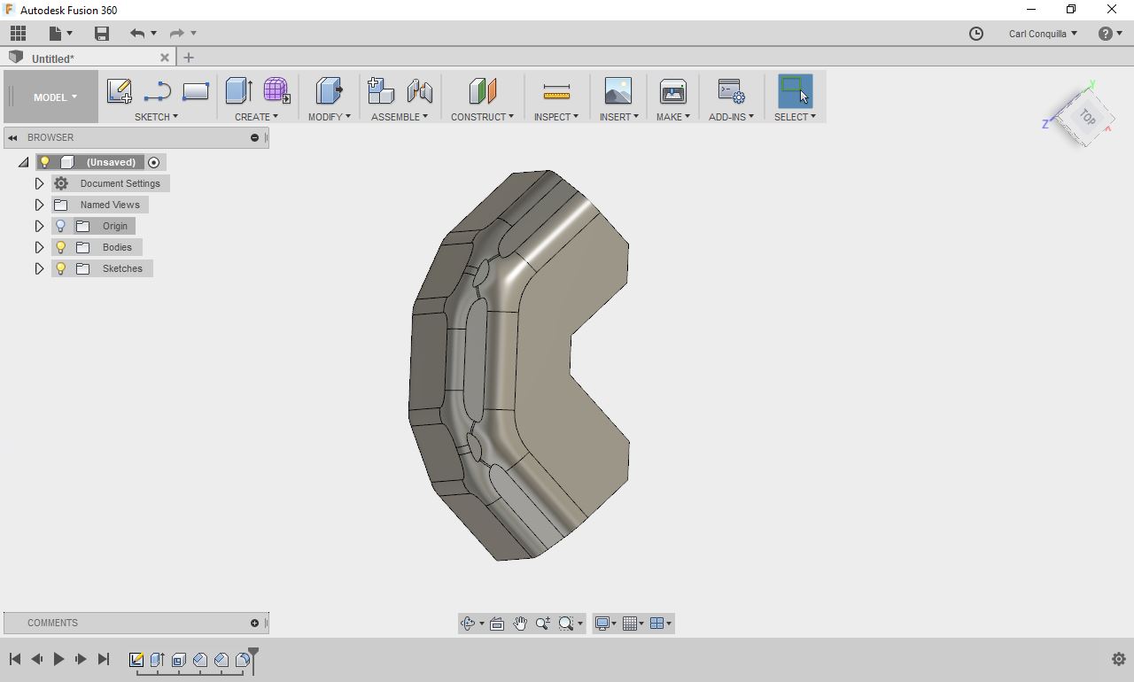
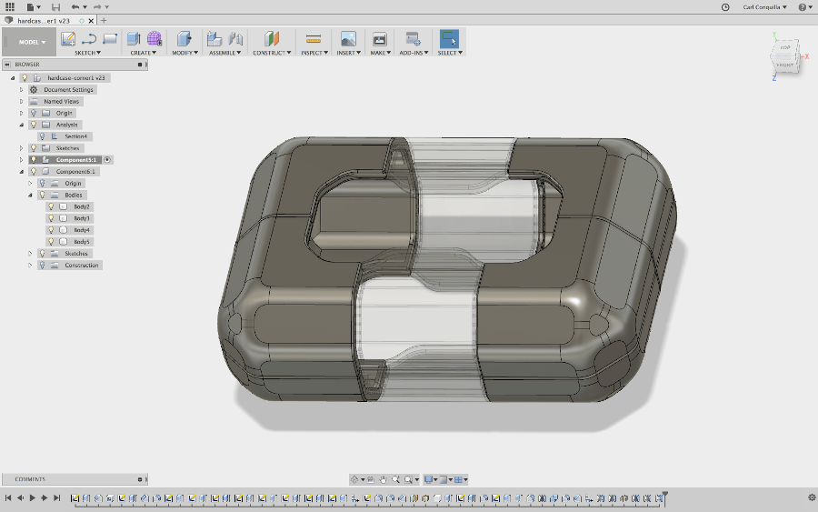
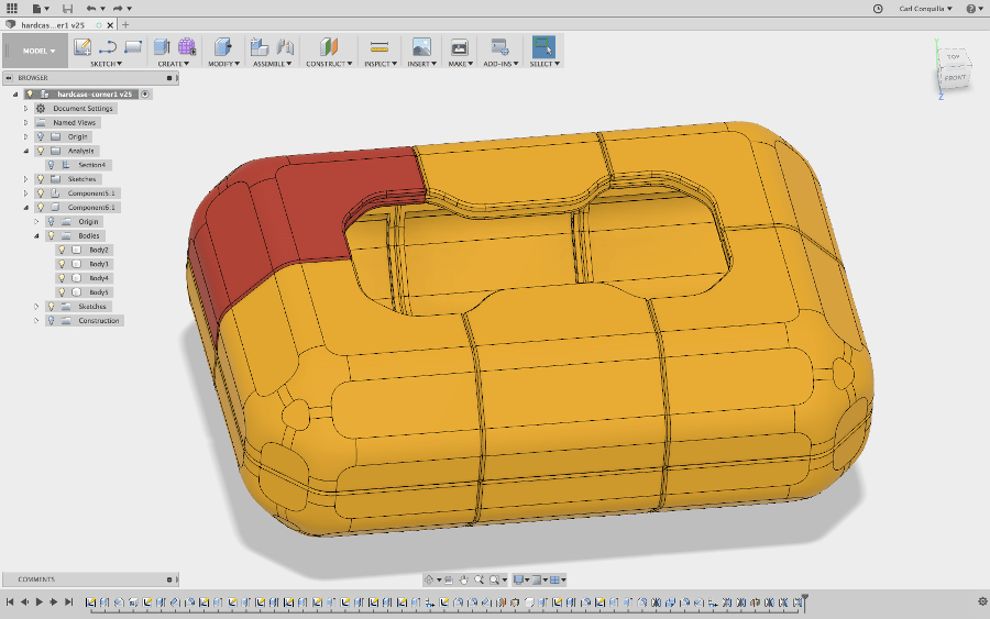
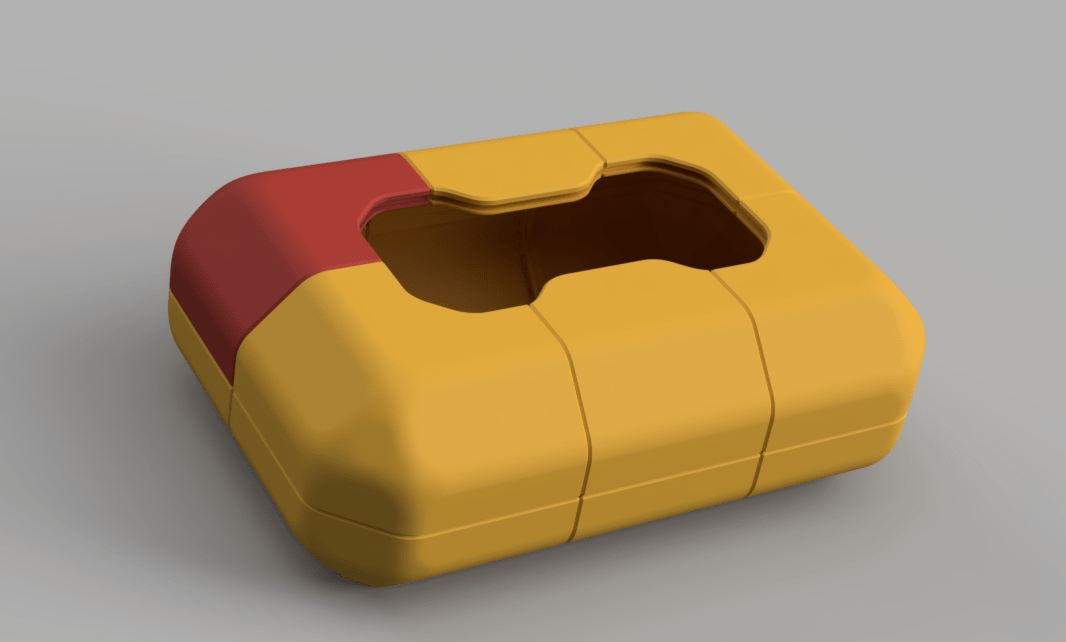
I'd been meaning to buy a hard case for all the stuff I bought from the electronics markets in China but Wendy and I went to the shops and after seeing the price of a genuine Nanuk case Wendy inspired me to print a case instead. Given the huge amounts of machine resources at FabLabUAE and the abundance of orange ABS I decided I would try it out as a sub-project!This also means I'd be able to store my final project in something protective while I travel.
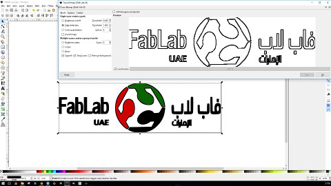
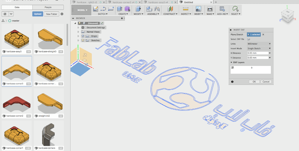
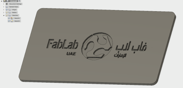
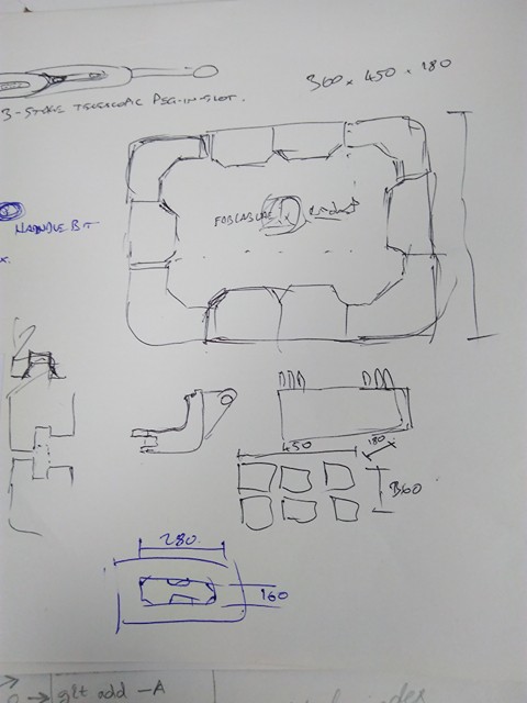 The idea is that each segment needs to be able to fit in the print bed (180x180x300mm roughly for each segment). Also I'll use some kind of plywood or other as the flat panels. I'll also machine or etch the panel with the FabLabUAE logo for bonus levels of awesome. I'll need to use Inkscape to vectorise the logo and send it to Fusion 360.
How to design things fast and learn to do other stuff fast too
There are many ways to start designing a part, one thing that I've found that helps (at least initially) is to pretend I was a CNC machine and trying to model the part that way.To do this I start with a big block roughly the size of the part I'm modelling. Then I draw sketches on the front, side and top views of the part, and use an extruded cut to remove material and make the outline shape of what I have in my head.
This is a fast way to get a quick shape, and understand the geometries involved in 3D space. After this I might do some fine tuning of any angles and lengths in my sketches, then I'll finish up by using the fillet and shell tools to round out the model.
My next favourite tool (after fillet of course), is the shell tool. Basically you select a face and it hollows out the remaining faces of your part to the thickness you specify. This is a particularly efficient operation for creating, say a box with filleted edges, because you don't have to worry about creating walls. You simply model the outside of the box, and click on the lid to remove, and tell Fusion how thick you want the walls to be.
It really takes practice to understand when and where to use these tools, and sometimes (ok, a lot of the time..) what you thought a tool would do simply doesn't work.
It's ok though, you can get by on a healthy breakfast of extrudes, extruded cuts, fillets and shelling for a long time before you feel the need to move to any of the other features.
Single sided machining - roughing
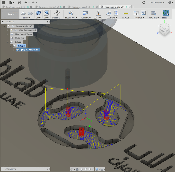
To use the CAM tools in Fusion you go through the menu on the top left (that usually says "Model") . From there you basically work left-to-right on the top menu, starting with "Setup".
The Setup defines things like which way your part will be facing in the machine, how much material around your part there is to remove.
Next you start with an operation - there's 2D and 3D types of operations, as well as turning and cutting. I'm not fully on top of the different operations, so I stick with adaptive clearing for majority of what I would need.
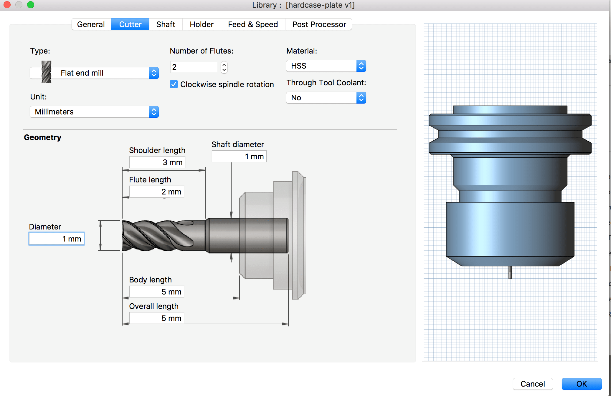
When you pick an operation it's going to ask you for a profile to cut, and then things like the tool you will use and how fine you want to cut.
This is useful because usually you want to do a roughing pass and you don't want to rough too close to where the final part will be. Depending on your material and tools, you can leave 0.5mm to 1mm of material on the workpiece during the roughing pass, and Fusion CAM will know to remove it later when you configure your finishing pass.
The really awesome thing I like about Fusion's CAM is how easily you can update the parameters for your operations and it recalculates your toolpaths. THEN, you can go through and view the simulation of material being removed so you can make yourself familiar with how the machine will move. An amazing feature, especially if you've never done that sort of thing before!
Cheatsheet for Fusion, and other commands I like to have on speed dial
Shortcuts:Sketch:
+ Line (L)
+ Dimension (D) - Smart dimensioning tool. Use it to define lengths, diameters, distances and angles. You can click two objects to define a distance or angle between them. However, for distances of zero I prefer to use the coincident or tangent relationship instead.
+ Rectangle (R)
+ Circle (C)
+ Trim (T)
+ Offset (O)
Features:
+ Extrude (E)
+ Fillet (F)
And other commands I like to have on speed dial:
Sketch:
+ Point - For those pesky points you want to refer to but don't automatically form references. Some intersections for example, won't automatically let you select them. Centres of complex shapes also
You can apply dimensions to points too, say you want to refer to a point 2/3 the dimension of a line. just make sure you set up the relationships for your point object.
Features:
+ Shell
+ Mirror
+ Pattern (Circular and Linear)
+ Sweep
+ Chamfer
+ Split body - Splits a body by a shape that you've defined, even if they are touching.
+ Combine - Combines two or more bodies so long as they are touching.
Other top tips:
+ Use the timeline at the bottom of the window. The little grey line at the end you can drag left and right to see where changes have been made.
This is super useful if you are trying to debug something that went wrong, or if you came back to your design the next morning and couldn't remember what you did! (Also namely if you're working on someone else's design, you can reverse engineer what they did.)
+ Use the lightbulbs in the design tree - you can hide and show things you do/don't want to see at the time.
Say if you want to use an older sketch you can set it to "Show" or 'lightbulb on' and you will be able to use an existing sketch you had drawn.
Single sided machining - finishing tool

Single sided machining with clamps
The next part I want to machine is going to be a bicycle sprocket. I'm writing this with the intention my mate Chester will find it and be able to follow similar steps in our workshop back home. I think it also helps a lot to model your part as if you were machining it away - that is, to start with a block and extruded-cut away to make your final shape as opposed to building a model out of extrudes.
I also purposely made the shapes non-square and put the sprocket not in the middle because it's easy to forget that the real world is usually not square at all unless you machine it to be so!

Double sided machining with clamps
I haven't quite made it up to this point yet. I intend to finish this off at a later time. I was in the process of watching some explanations of different ways you can do it. My research came up with three effective methods:- Over-extrude and over-cut then flip the part and mill the face down - Only works if the part has a flat end face
- Machine a fixture for the part - Works best if the part fits snugly (like, verrrry snug) and won't rotate in the fixture
- Model the clamps into the 'CAM setup' in the software - Can work if you know where the clamps are going to be, but not always do-able
xDesign
We didn't hear anything about gaining access to this in the end. I'm still pretty excited to check out how Dassault executes a Fusion-esque cloud-served package but unfortunately it will have to wait.
Blender
- The user interface (crazy!)
- Space - Brings up a function search so you can quickly find things instead of clicking through all the menus. Useful if you remember what a function is called or if there are a bunch that do similar things and you want to compare them to see which one you want.
- Right click - Select. A bit weird at first. Honestly, who selects things with right click..?
- x - Delete
- r - Rotate. You can also confine to X, Y or Z axis by pressing x, y or z.
- g - Grab (move). Like the rotate function you can also confine to X, Y or Z axis by pressing x, y or z.
- s - Scale. You can also scale in only the X, Y or Z axes by pressing x, y or z.
- Tab - Swaps between Object mode and Edit mode. Object mode is for inserting or moving objects around within a scene, Edit mode is for editing the shape of objects. In my opinion they could have picked better words but I'd imagine you don't think about it too much after you've used it long enough.
- Edit mode works a bit differently, instead of selecting objects there are three different tyypes of things you can select: Points, Edges (vertices) and Faces. You still right click to select (which I'd argue is the wrong click but anyway..)
- b - Lets you select a bounding box of points, edges or faces. Useful for selecting all of that type within a region.
- e - Extrude. You can extrude faces from the model, select the face and press e.
- Ctrl+r - This is a function called subdivide. You can add a division within a shape. Also, by using the scroll wheel you can add more equally spaced subdivisions. This is actually a very useful way of adding resolution to the shape of your model (You'll see what I mean by this when you try it!).
- Lastly there are some functions that work for joining two objects together. You would do this to join say a cube and a cylinder to make a compound shape.
- Ctrl+j - Join selected objects so they can be available in Edit mode at the same time.
- f - Create a face between two or more edges. This is awesome for when you have joined two objects that aren't quite in contact or their meshes don't merge smoothly with eachother. You can create faces to merge two shapes into one mesh.
- Making shapes This Youtuber has an awesome anvil modelling exercise.
Blender's got some crazy stuff going on in it's user interface. No doubt very powerful, but quite difficult to do casual or precise modelling in. Also, unlike SolidWorks or Fusion you would most definitely need a mouse to be able to work the interface. I bet there's plenty of cheat sheets for the keyboard shortcuts but here's a couple I found most useful for starting off:


All in all Blender seems to be up high there on the starting difficulty, and feels quite time consuming but I've done enough software to know that it just takes time and application to learn the common patterns and shortcuts to make an efficient work flow.

He also makes a great point that you could get three people to model the same object and each one would do it differently. There's no right way to start a model but there are some tricks you can use through experience and practise that will help you use your time efficiently and also allow for less headaches when applying changes later on.
Funnily enough I actually managed to overheat my computer while trying to run Blender at one point. For anyone curious here's what it looks like a few minutes after taking the case off the computer and cooling it down enough for it to restart.
 Unreal Engine
So the interface for this is a bit hectic. Unreal Engine as far as I understand is optimised for high-level graphics and for displaying large amounts of objects on a terrain, all rendered in near-realtime on an as-needed basis (for example, the engine would decide not to render objects out of view or that are sufficiently far from a camera view).
As such it took me a while to figure out how to actually draw models. I spent a bit of time playing around with placing assets though, as you can see I imported a cube and a sphere, then I added a rock to a chair.. etc. The perspective view (left) allows you to walk around as if you were in the environent, and the real-time rendering will do as good a job as it can.

It seems pretty clever - the UI asked me if I wanted to dial the graphics settings back since it had detected 30 seconds continuous of output below 10 frames per second. You can also see the top wireframe view (also left).
After looking through a bunch of tutorials it appears that everybody prefers to generate their assets elsewhere in say Maya or Blender. I'd imagine it to be a lot more efficient that way and then importing assets to be used in the engine would be significantly simpler. Unreal is much better suited to laying out landscapes and terrain or perhaps buildings.
Antimony
I'd never even heard of this one before but it's an interesting visual representation of the relationships between shapes. As far as I remember it uses a similar style to OpenSCAD in that you create geometries that react to each other by way of functions. Antimony functions are written in Python and the rendering of the model appears to happen in realtime (which is pretty cool, but a lot of the time not so useful!).
Making shapes
Here I made a couple of quick shapes and tried out some interactions. This is the user interface when you open up and you can see I've created a cube with rounded edges, and a sphere. Then I used a subtraction function to remove the sphere volume from the cube.
You can see the code for the rounded cube written in Python. There are a couple variables for width, height, depth and radius.
Next I tried a function called "cylinder wrap". You can see it has attempted to warp the shape I made into a cylinder. I'm not exactly sure how this works because smaller values for the coefficient resulted in a thin circular ring and values above 2 were thich circular rings. This value is 1.5, and it makes the cube look like some kind of groovy card holder.
The main thing I was interested in though was the blend function. The last three images are blends between the shape I made originally and a cube with sharp corners of 2x2x2 dimensions. What happens is that the corners of the inner cube are drawn to the faces of the spherical hole in the parent cube.
The inner corners of the parent cube are also drawn inwards to the corners of the sharp cube, and I captured a couple of different orientations of this because it looked so cool.
Unfortunately I encountered a bug where I couldn't save the STL for printing but perhaps one day I can look through the nodes I've used and rebuild it quickly when STL export is working again!
[edit: I disagree with myself it wasn't a bug the export feature is inserted as a node and I didn't see it! However, the STL generation must be pretty poorly optimised as the file itself at a reasonable resolution is around 90MB, while the low-res version is about 9MB (pictured below). You can catch the design files in design files list, which doesn't include any STLs because of their size.]


Video editing
I had the best intentions to try this out but I didn't get around to it. I'd been meaning to put together a few short videos of my trips to Uluru and Shenzhen, but I only got to the point of loading all the videos and realising how many there were.
Maybe next week I'll get to go through the videos. Spent too much time on 3D this week instead. The software that was recommended to me was Kden but I didn't actually find it too appealing to work with (the importing media screen is some crappy file browser window that didn't even support CTRL+A).

Parting words
Sorry for writing so much! I hope you learned at least one useful thing in all of this! Next week I'll try to move over to a markdown architecture for my pages so I can actually see how much I have written and edit more easily - I've been writing all this in HTML so far! I had planned to do it this week but I couldn't get Strapdown to work. If anyone knows how to do it please PLEASE let me know!
Also, I had planned to use a lot more of the newer software than ones I've already used. Unfortunately Unreal turned out to not be quite what I thought it would be and couldn't get my hands on xDesign. I wish I had spent a lot more time with KdenLive and Blender before getting frustrated, I think if I had more inspiration or models I could apply some learning exercises to I would be able to dedicate the time.
I am pretty pleased however that I got through significantly more in SolidWorks and Fusion 360 than I had anticipated and thoroughly learned a lot even if it meant my software mastery becoming more specific than general in the end.
Note to Carl: Check out Typora or otherwise.
Design files for this week can be found at Design Files.