What our assignment is that to Design and build a wired &/or wireless network connecting at least two processors
The Inter-integrated Circuit (I2C) Protocol is a protocol intended to allow multiple “slave” digital integrated circuits (“chips”) to communicate with one or more “master” chips. It only requires two signal wires to exchange information.
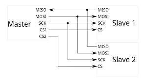
Each I2C bus consists of two signals: SCL and SDA. SCL is the clock signal, and SDA is the data signal. I²C uses only two bidirectional open-drain lines, Serial Data Line (SDA) and Serial Clock Line (SCL), pulled up with resistors. Typical voltages used are +5 V or +3.3 V, although systems with other voltages are permitted.(wiki)This document gives much more details about i2c.
So I'm planing to work with I2C Protocol to do communication between 2 boards with Atmega328p as the master and a Attiny44 as slave.
Board Schematics, Designs and PCB assembly
I already have an Atmega328p board that was fabricated on week 11 assignment and driver board which was fabbed in week 12 to be used as slave. But I decided to mill it again as a backup because there was couple of mistakes with that board.
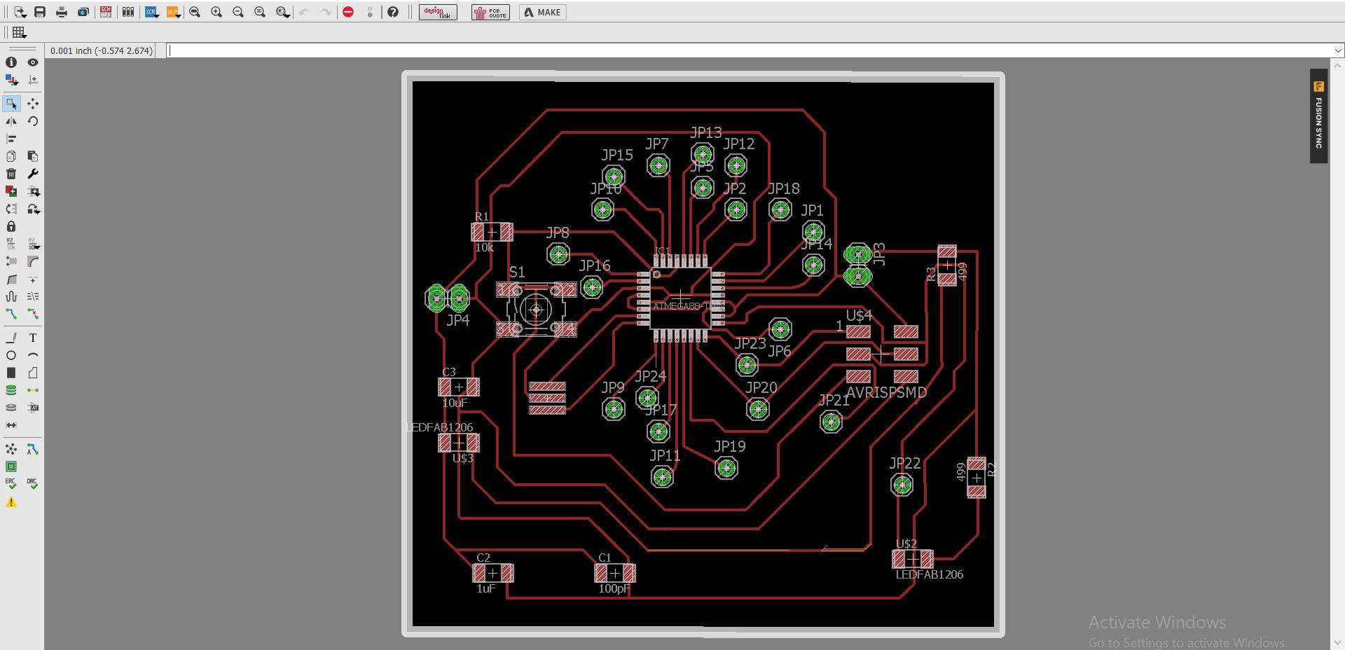
The schematic and board designs after rectifing the issues that occured in week 12,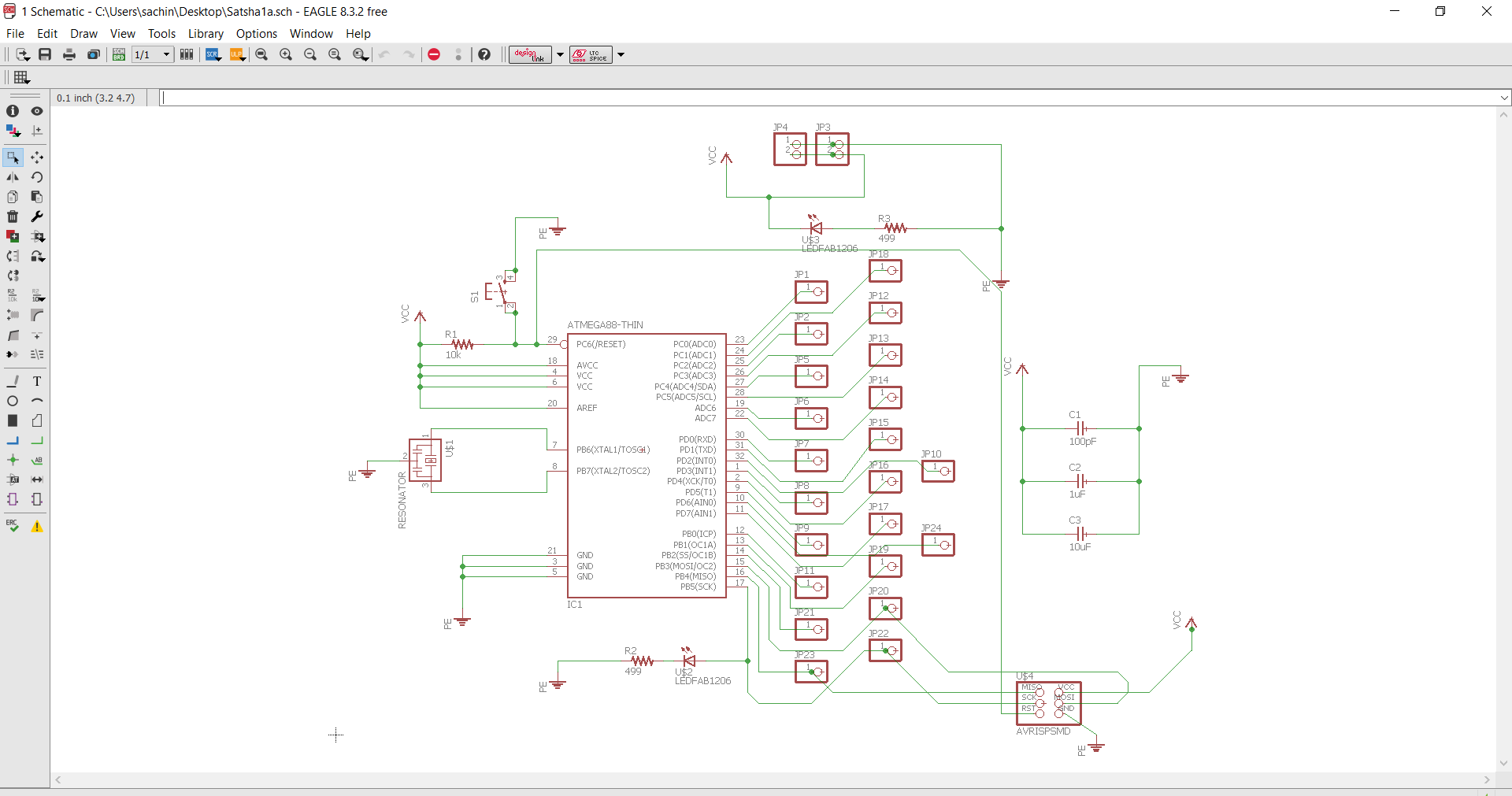
After converting into .png I began to mill. Milling went very well. Then next is the cut portion. In cut, what modella do is that it make the holes in the portion wherever it is needed. But here the bit has displaced a bit and it reflected in my board.
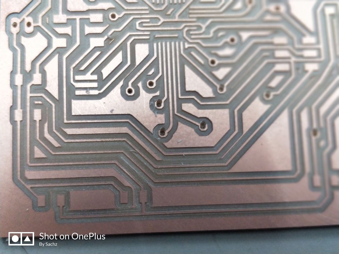
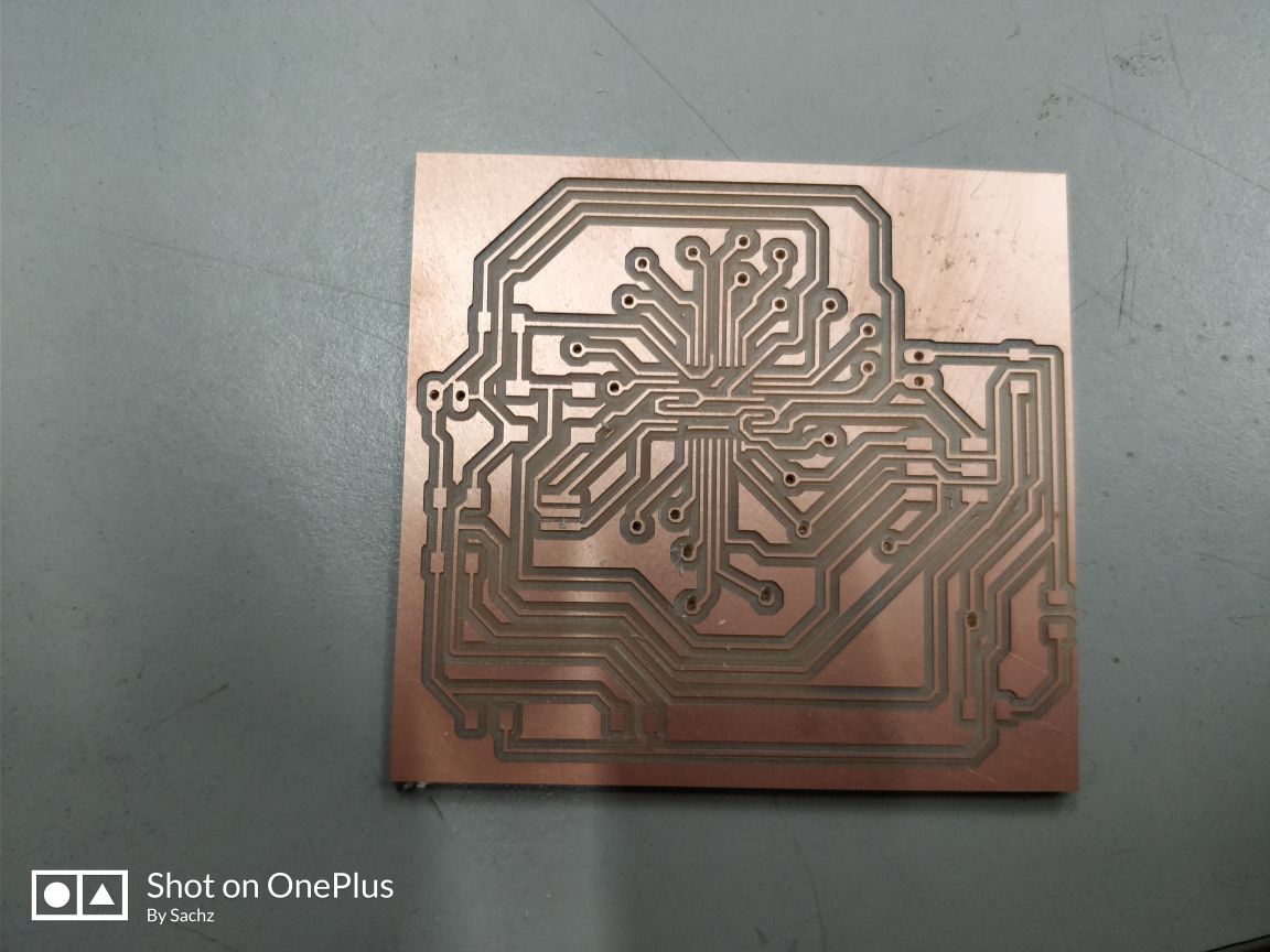
Bit displaced and normal is clearly visible ib the picture.
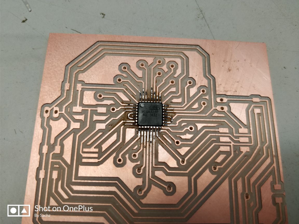
Next is to solder my components and it was little difficult to solder the IC as it is so small and the legs are so closely packed.
I burned the following codes to the respective boards using FabISP.
I2C master code
  // Wire Master Writer
// by Nicholas Zambetti

// Demonstrates use of the Wire library
// Writes data to an I2C/TWI slave device
// Refer to the "Wire Slave Receiver" example for use with this

// Created 29 March 2006

// This example code is in the public domain.


#include < Wire.h>

int sense = 0;
int value = 0;
void setup() {
  Wire.begin(); // join i2c bus (address optional for master)
  pinMode(13, OUTPUT);
}

//byte x = 0;

void loop() {
  value = analogRead(sense);
  value = value/10;
  Wire.beginTransmission(8);
  if (value < 50)
  {
    digitalWrite(13, HIGH);
    Wire.write("s");
  }
  else
  {
    digitalWrite(13, LOW);
    Wire.write("n");
  }
//  digitalWrite(13, HIGH);
//  Wire.beginTransmission(8); // transmit to device #8
//  Wire.write("x is ");        // sends five bytes
//  Wire.write(x);              // sends one byte
//  Wire.write(x);
  Wire.endTransmission();    // stop transmitting

//  x++;
  delay(500);
//  digitalWrite(13, LOW);
//  delay(500);
}
I2C Slave code
// Wire Slave Receiver
// by Nicholas Zambetti < http://www.zambetti.com>

// Demonstrates use of the Wire library
// Receives data as an I2C/TWI slave device
// Refer to the "Wire Master Writer" example for use with this

// Created 29 March 2006

// This example code is in the public domain.


#include

void setup() {
  Wire.begin(8);                // join i2c bus with address #8
  Wire.onReceive(receiveEvent); // register event
  pinMode(13, OUTPUT);
//  Serial.begin(9600);           // start serial for output
}

void loop() {
  delay(500);
}

// function that executes whenever data is received from master
// this function is registered as an event, see setup()
void receiveEvent(int howMany) {
//  while (1 < Wire.available()) { // loop through all but the last
//    char c = Wire.read(); // receive byte as a character
//    Serial.print(c);         // print the character
//  }
//  int x = Wire.read();    // receive byte as an integer
char c = Wire.read();
//  Serial.println(x);         // print the integer
//  Serial.println(x%5);
//  if (x%5 == 0)
if (c == 's')
  {
    digitalWrite(13, HIGH);
  }
  if (c == 'n')
  {
    digitalWrite(13, LOW);
  }

}
The video showcasing the working. It lights up when the moisture value is above the threshold set which is 50.
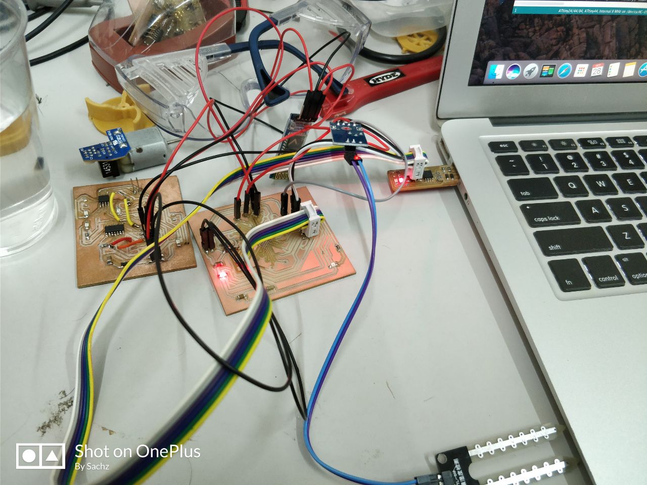
Attiny44 now would act as the Slave and Atmega328p as the master. Connected SDA of ATTiny44 PIN7 with Pin27 of Atmega328p and SCL of ATtiny44 PIN9 with Atmega328p's PIN 28.
I refered Ganadev's week15 week for burning Arduino bootloader into Atmega board. The slave with address number (8) will only receive the transmission from the master. When it receives the data, output LED blinks.
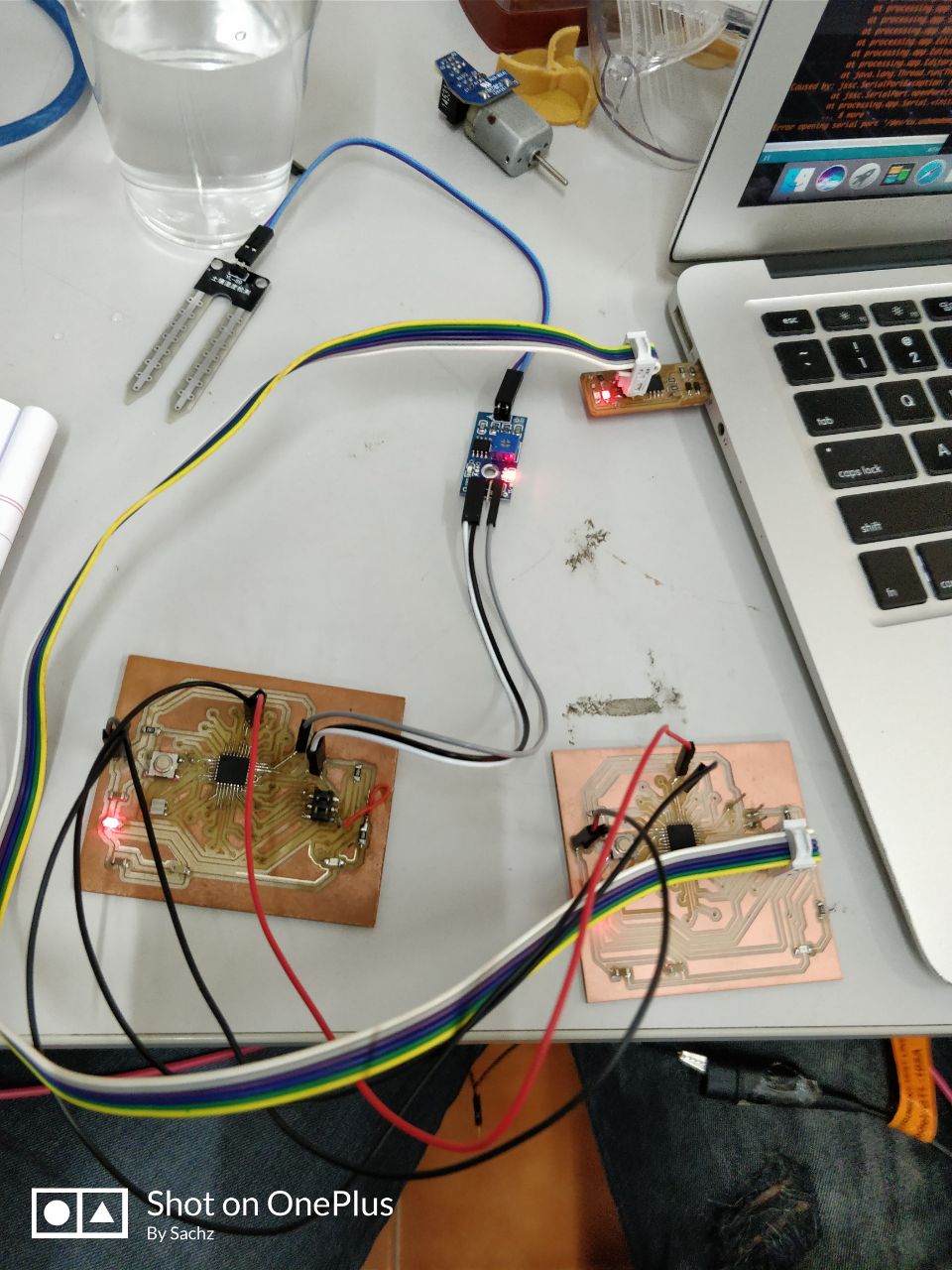
The following is the setup I used to work on networking, I connected the SDA & SCL of the master IC to SDA & SCL of the slave IC respectively
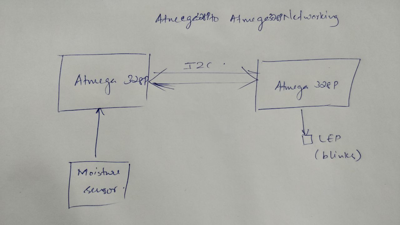
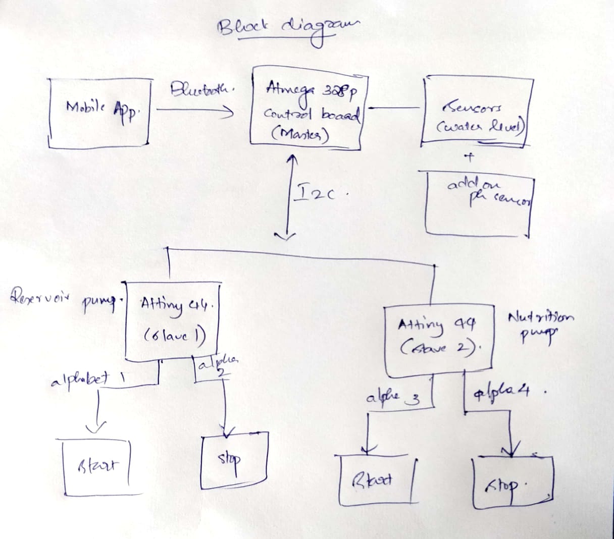
The following is the final project block diagram. So I also wanted to test serial communication via bluetooth as well.
The following are the codes for I2C communication between Atmega328p as master and Attiny44 as slave.
Atmega328p Master
//Master - Atmega 328p

#include

//int sense = 0;
//int value = 0;
char BluetoothData;
void setup() {
  Wire.begin(); // join i2c bus (address optional for master)
  pinMode(13, OUTPUT);
  Serial.begin(9600);
}

void loop() {
//  value = analogRead(sense);
//  value = value/10;
  Wire.beginTransmission(8);

  if (Serial.available()) {
    BluetoothData = Serial.read();
    Serial.print(BluetoothData);
    if(BluetoothData)
    {
      digitalWrite(13, HIGH);
      Wire.write("s");
    }
    else
    {
      digitalWrite(13, LOW);
      Wire.write("n");
    }
//    switch(BluetoothData)
//    {
//      case 's': digitalWrite(13, HIGH);
//                Wire.write("s");
//                break;
//      case 'n': digitalWrite(13, LOW);
//                Wire.write("n");
//                break;
//      default: digitalWrite(13, HIGH);
//               Wire.write("s");
//               delay(100);
//               break;
//    }

  }
//  else
//  {
//    if (value < 50)
//    {
//      digitalWrite(13, HIGH);
//      Wire.write("s");
//    }
//    else
//    {
//      digitalWrite(13, LOW);
//      Wire.write("n");
//    }
//  }

  Wire.endTransmission();    // stop transmitting
  delay(500);

}
Attiny44 as slave
//Slave - Attiny44

#include


void setup() {
  pinMode(2, OUTPUT);
  pinMode(3, OUTPUT);
  TinyWireS.begin(2);                // join i2c bus with address #8

}

// function that executes whenever data is received from master
// this function is registered as an event, see setup()

void loop() {

  char c = TinyWireS.receive();

  //  Serial.println(x);         // print the integer
  //  Serial.println(x%5);
  //  if (x%5 == 0)

  if (c == 'l')
  {
    digitalWrite(2, HIGH);
  }
  if (c == 'n')
  {
    digitalWrite(2, LOW);
    digitalWrite(3, LOW);
  }         // print the integer
  if (c == 'r')
  {
    digitalWrite(3, HIGH);
  }
}
Mositure sensing programme
I2C with Atmega328p as master and Atmega328p as slaveMaster Slave I2C with Atmega328p as master and Attiny44 as slave
Master Slave Go back HOME