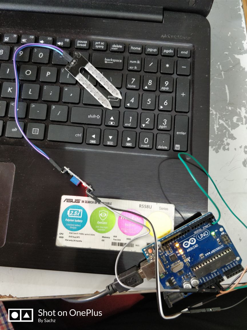
So here what we are assigned do is that to measure something:add a sensor to a microcontroller board that we have designed and read it
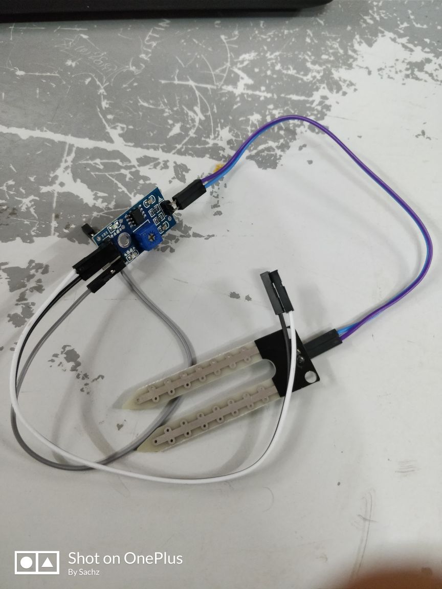
I wanted to test out the moisture sensor which I plan to use it on my final project. So along with that I wanted to do a board which would also have enough pinouts that would satisfy my requirement for that final project. Thus went for the atmega328p microcontroller we have at our lab. I also refered Daniele Ingrassa's Satsha kit for the schematic. His work is an improvement on FabKit. Also using Satsha kit, I could use Arduino IDE for writing code and programming.
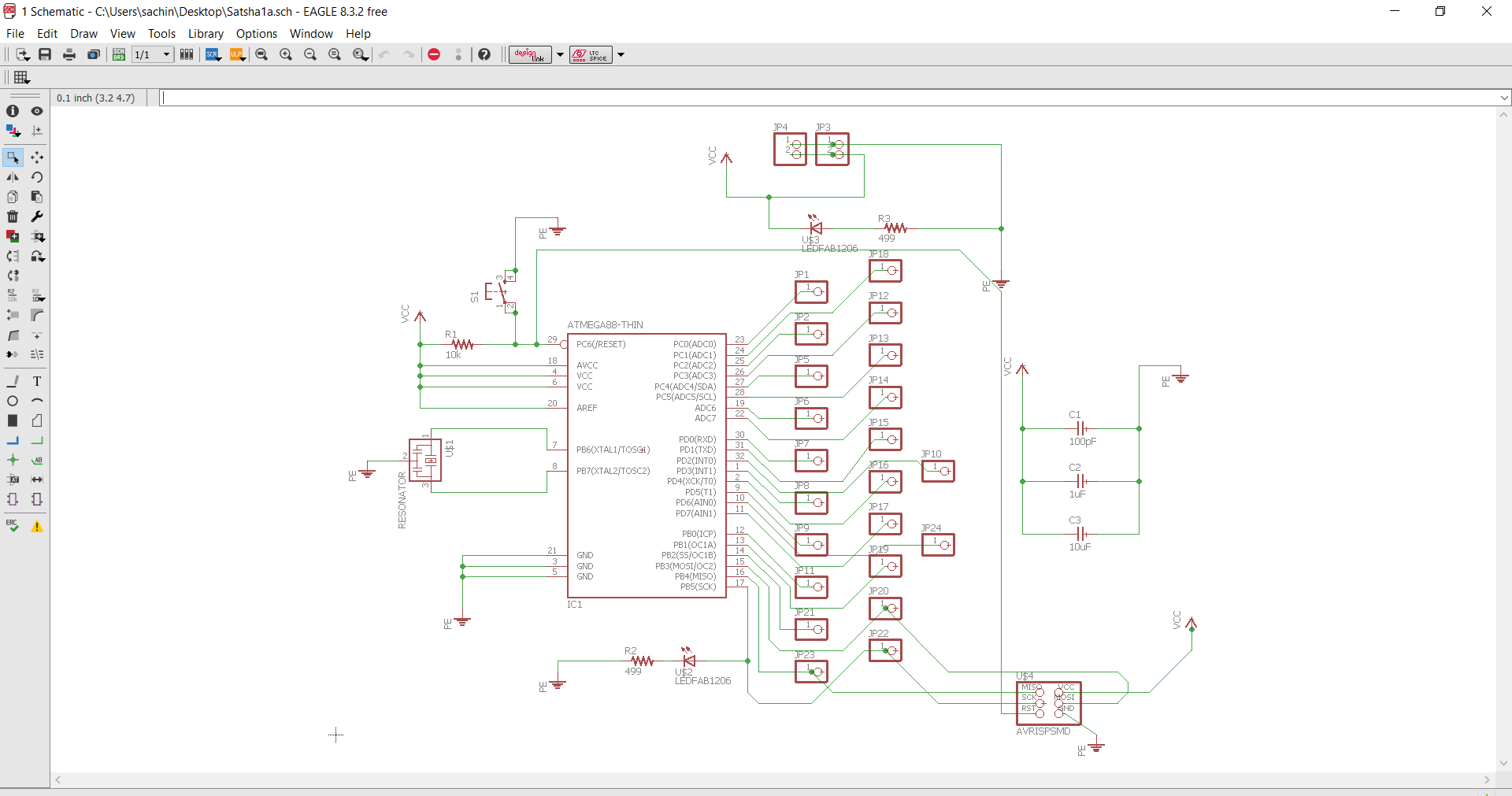
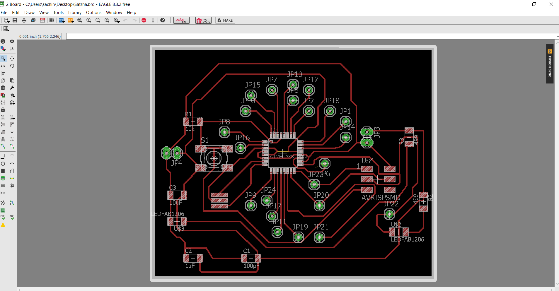
The documentation of using Eagle to build the schematic and board design as explained on Electronic Design week.
About Atmega328
Some of the Features of ATMEGA 328 are
- 1.8-5.5V operating range
- Up to 20MHz
- 32kB Flash program memory
- 1kB EEPROM
- 2kB Internal SRAM
- Two 8-bit Timer/Counters
- One 16-bit Timer/Counter
- RTC with separate oscillator
- 6 PWM Channels
- 8 Channel 10-bit ADC
- Serial USART
- Master/Slave SPI interface
- 2-wire (I2C) interface
- Watchdog timer
- Analog comparator
- Data retention: 20 years at 85C/ 100 years at 25C
- 23 IO lines
void setup() {
  // initialize serial communication at 9600 bits per second:
  Serial.begin(9600);
}

// the loop routine runs over and over again forever:
void loop() {
  // read the input on analog pin 0:
  int sensorValue = analogRead(A0);
  // print out the value you read:
  Serial.println(sensorValue);
  delay(1);        // delay in between reads for stability
}
Here in Arduino board, set a value of 50 and when the sensor is dipped in the water, the value should get increased and the LED should have to glow.
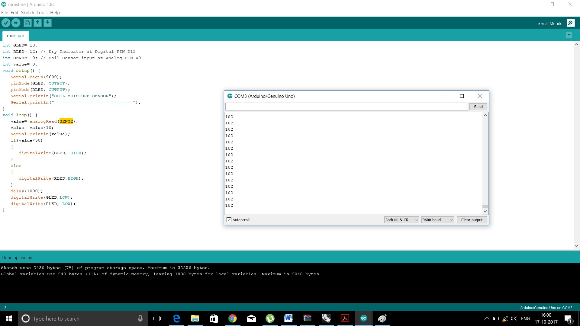
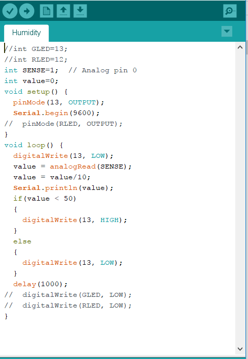
The LED is connected to the 13th pin on the Satsha board. The LED lights up when it goes past the threshold value of 50.
Programe file here
design files here
design files here
Go back HOME