So this week, we are intented to add an output device to the microcontroller in the board which we have designed and to programme it to do something. For this week’s assignment I thought of adding DC motor as my output since it is needed for the final project in which the pump is needed to rotate.
So what here first needed is that a motor driver board. It takes a low current control signal and then turn it into a high current signal that can drive a motor. For that I used ATTiny44.Designing the board
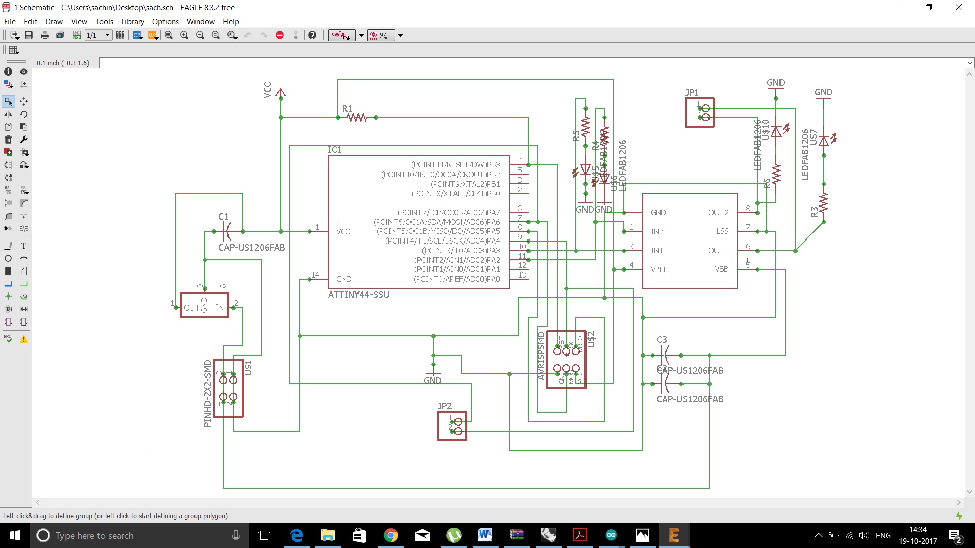
Details of designing the board is given in the Electronics Production week. Here I thought of recreating hello.H-bridge board to run the DC motor which is avalable in our lab. An H bridge is an electronic circuit that enables a voltage to be applied across a load in opposite direction. These circuits are often used in robotics and other applications to allow DC motors to run forwards or backwards. By using this H-Bridge, we can acyually control the current in the motor and hence the direction of rotation. Here input voltage that used is 5V.
Since we are using Attiny44, we have to go through the datasheet of Attiny44 in detail.ATtiny44 Datasheet Review
8-Bit Microcontroller with RISC Architecture with Most Single Clock Cycle Execution
– 32 x 8 General Purpose Working Registers
– 4K Bytes of In-System Programmable Program Memory Flash
–56 Bytes of In-System Programmable EEPROM
–256 Bytes of Internal SRAM
Peripheral Features
– One 8-Bit and One 16-Bit Timer/Counter with Two PWM Channels, Each
– 10-bit ADC
– Programmable Watchdog Timer with Separate On-chip Oscillator
– On-chip Analog Comparator
– Universal Serial Interface
Special Microcontroller Features
– debugWIRE On-chip Debug System
– In-System Programmable via SPI Port
– Internal and External Interrupt Sources
– Enhanced Power-on Reset Circuit
– Programmable Brown-out Detection Circuit
– Internal Calibrated Oscillator
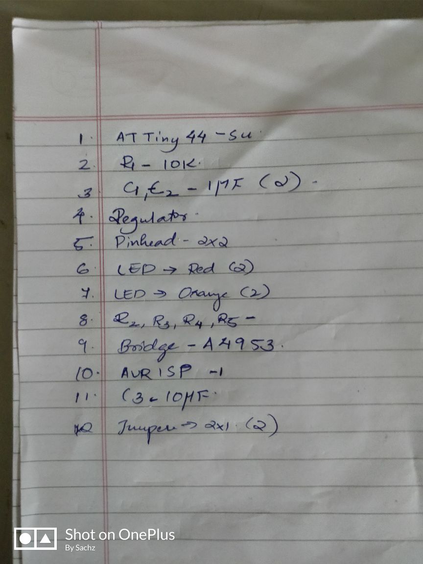
Components needed
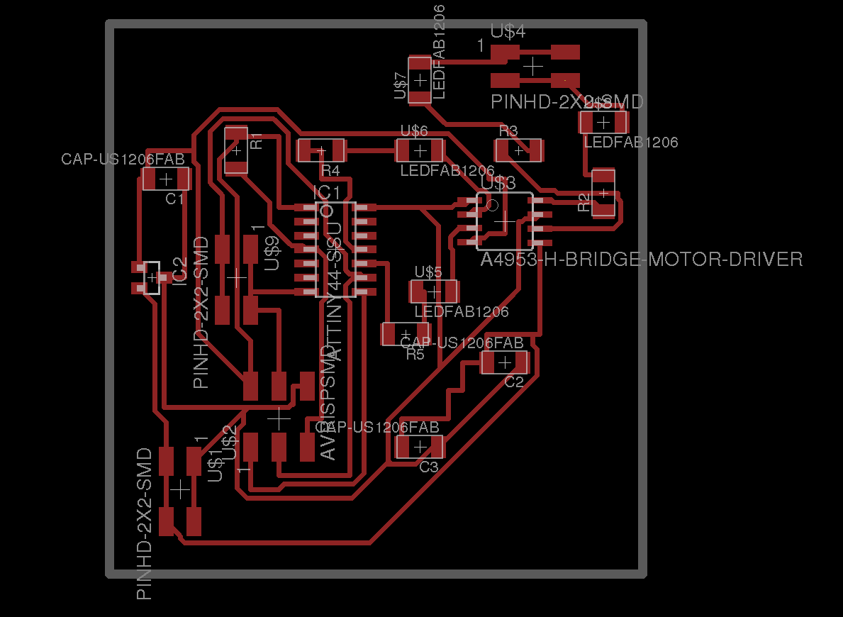
Making the Board
Details of milling the board is given in the Electronics Design week.Since there was some issues with the modella, speed of the machine was not as expected and it resulted making the board to get completed much slower than expected.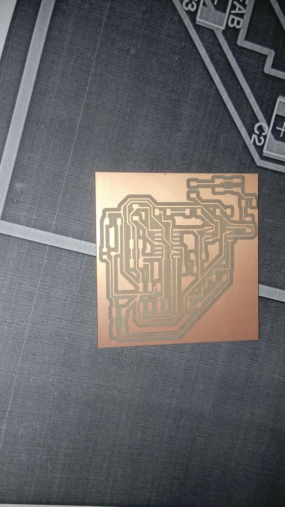
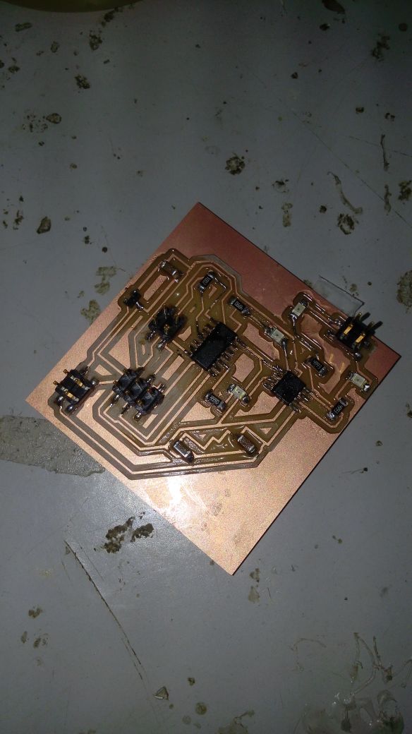
Finally my assembled board with PCB is ok.
Programming
Now I think to use the example of code "delay". Here the output are connected to the data of the microprocessor and so that programe has to made accordingly. Used FabISP for programming the board.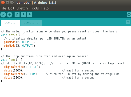
Download the Program file
design files here
design files here
Go back HOME