Week 4
-
COMPUTER-CONTROLLED CUTTING
Group Assignment
Characterize your lasercutter, making test part(s) that vary cutting settings and dimensions
Individual Assignment
Cut something on the vinylcutter design, lasercut, and document a parametric press-fit construction kit, accounting for the lasercutter kerf, which can be assembled in multiple ways
LASER CUTTER CHARACTERIZATION (Group Assignment)
Team members:
- Andrea Lazo
- Carlos Nina
- Renzo Chirinos
This group assignment has two parts. The first part is the characterization of the machine EPILOG Legend 36EXT. The second part is tha characterization of the machine TROTEC Speedy 400. The reason of this, is that TROTEC machine has a problem after our first characterization and we was unable to cut our pieces.
In both cases, the material for the test is 4mm thickness MDF.
EPILOG Legend 36EXT
The first objective is find the parameters to get a clean cut. The second step is measure the kerf of the machine. The last test is about tolerances. We need to find the tolerances to get a good press fit.
An important information is the Machine engraving area 36" x 24" (914 x 610 mm), more specs can be found here .
Important considerations before cutting:
- Focus the lens.
Basically it is ensure the right distance between the piece and the lens. This procedure require put a special tool over the lens and up the table, until touch the tool.

- Turn on the air extractor.
The laser cutting process produces contaminant gases. Is important turn on the extractor before start the cutting, in order to extract this contaminants efficiently.

- Set the machines parameters.
Read the machine documentation and prepare the parameters before cutting.

- Use eyes protection glasses.
The laser is a light beam of high energy. If the beam reach the retina can cause long term injuries.

For the first test, we create small squares, each one of them was cutted with different parameters of power and speed. The figures was drawn on Autocad, exported to .dxf format and later opened on CorelDraw (the machines in our Fab Lab are configured to be used with this software).
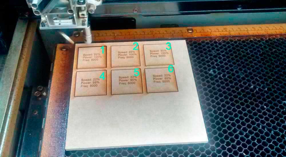
This test allow us to find the right parameters of the machine, that makes a good cut. Additionally, We can measure the kerf of the machine. The result of both is it:
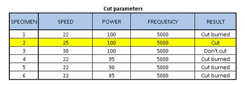
To calculate the kerf of this machine, we need to measure the outer borders and the inner borders of the cut, then divide this rest by 2.
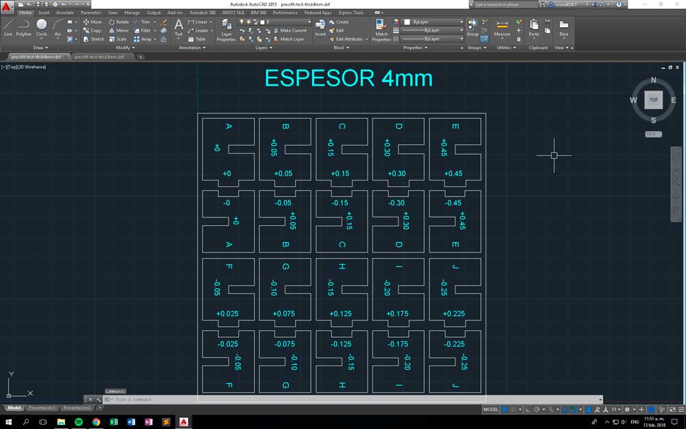
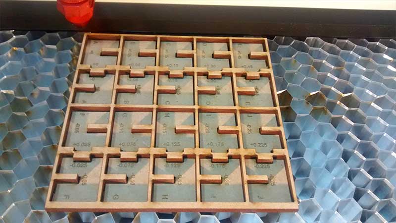
Finally we make a test to find the interference fit for our material. At this point, we make the test for two type of joints. One joint in form of "C" and a joint in form of "U". (well, we are not sure about this names).
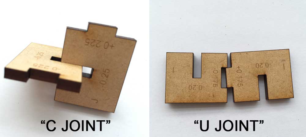
We did this shapes:
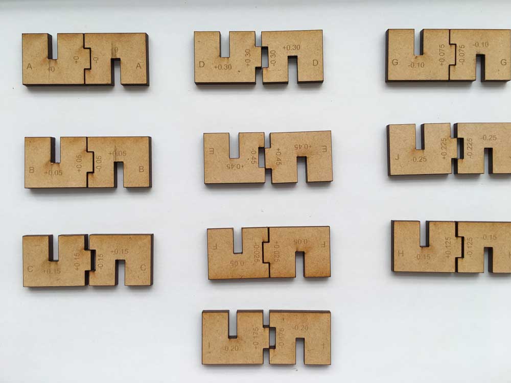
Interference fit on C joint is:
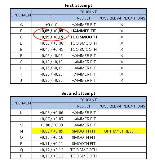
After first attempt, we note that fit was no optimal. So, we decide to make a second attempt, covering the values between +0.05 and +0.15. This time, we find an optimal value of +0.09 mm.
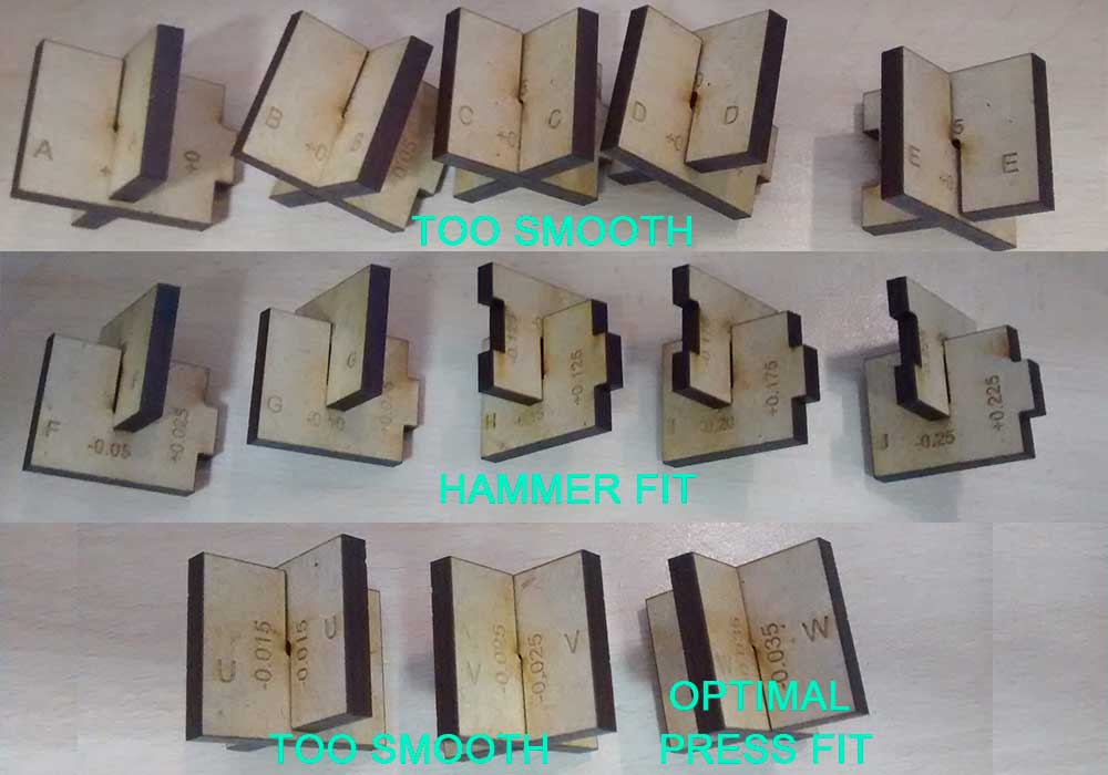
Interference fit on U joint is:
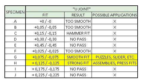
To the U joints, we found two useful values. A smooth fit, ideal to sliders or puzzles of +0.075/-0.075 and a strong fit ideal for press fits, of +0.125/-0.125.
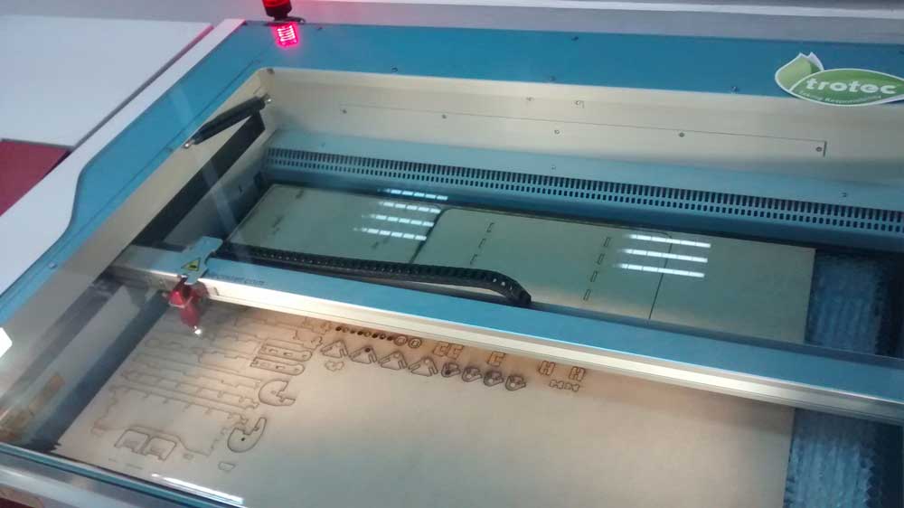
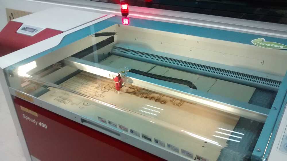
TROTEC Speedy 400
For this machine, the process is the same than previous.
An important information is the Machine engraving area 1000 x 610 mm (39 x 24 in), more specs can be found here .
Important considerations before cutting:
- Focus the lens.
Basically it is ensure the right distance between the piece and the lens. This procedure require put a special tool over the lens and up the table, until the tool fall, due to the contact with the material surface.
This procedure must be done before each cut job. The irregular height of the material surface, can affect the cut and leave zones uncut. - Turn on the air extractor.
In this machine, the air assistance can be configured from the software to each cut job. - Clean lens.
We notice, the lens on this machine can get dirty much faster than the epilog. So, keep the lens clean is an important consideration.

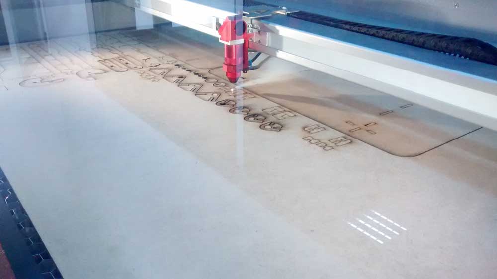
For the first test on this machine, we create small squares too. (The first 10 squares was made before clean the lens of machine, so we did it again)
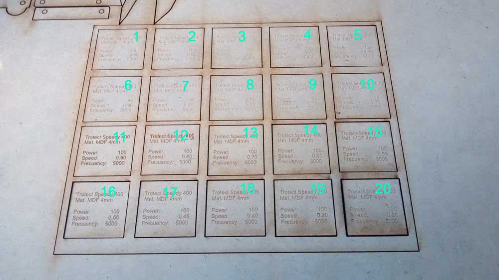
The result of the test is:
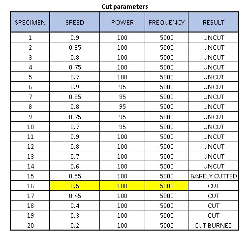
The best paratemeters to make a good quality cut are speed: 0.5, power:100 and frequency:5000, to 4mm MDF.
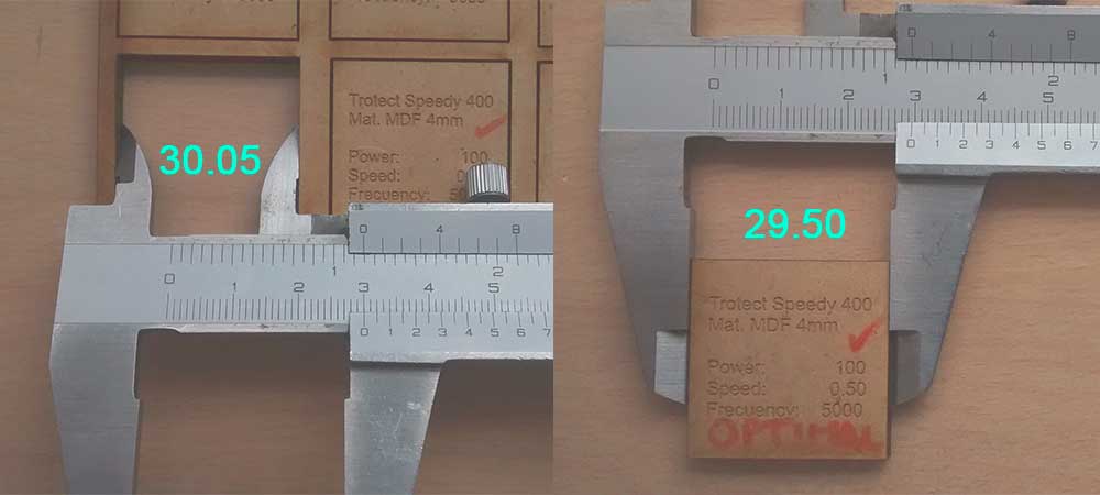
To calculate the kerf of machine, we need to measure the outer borders and the inner borders of the cut, then divide this rest by 2.
kerf = (30.05 - 29.50)/2
kerf = 0.275 mm
In this machine, we test the fit too. So, these are the results:
Interference fit on C joint is:
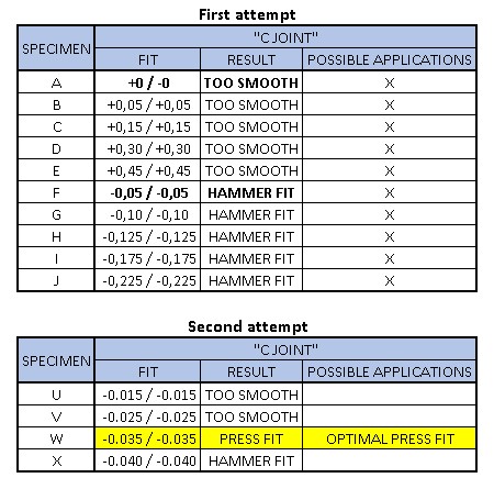
So, the optimal press fit is -0.035mm to a "C Joint"
Interference fit on U joint is:
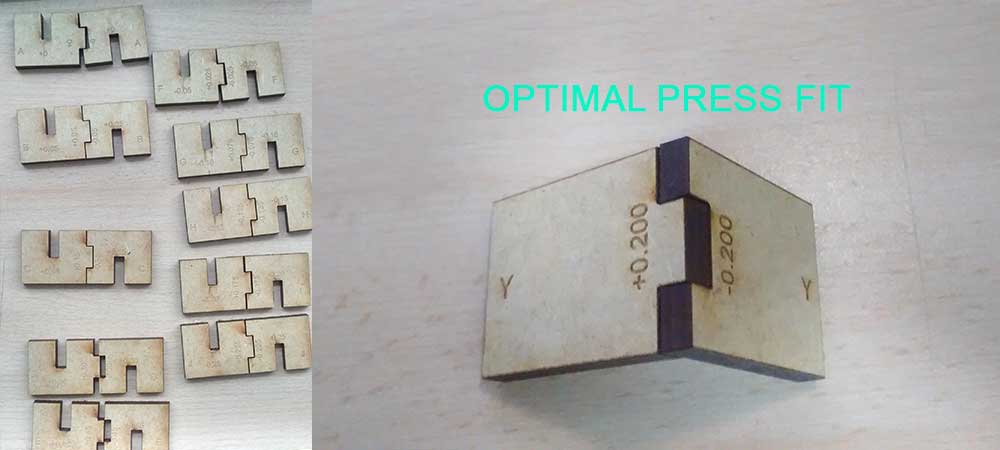
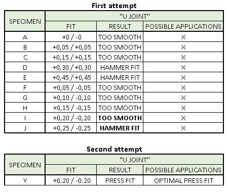
So, the optimal press fit is +/-0.2mm to a "U Joint"
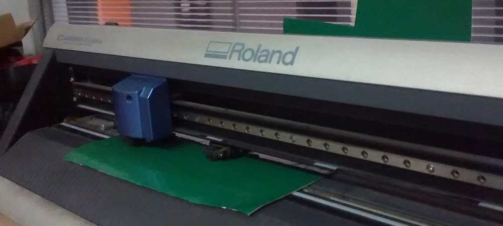
VINYLCUTTER DESIGN (Individual Assignment)
To this assignment, I decide to cut the Fab Academy Logo. On the first try, I use a color logo on PNG format.
After cut the vinyl, I was noticed that some letters didn't cutted.
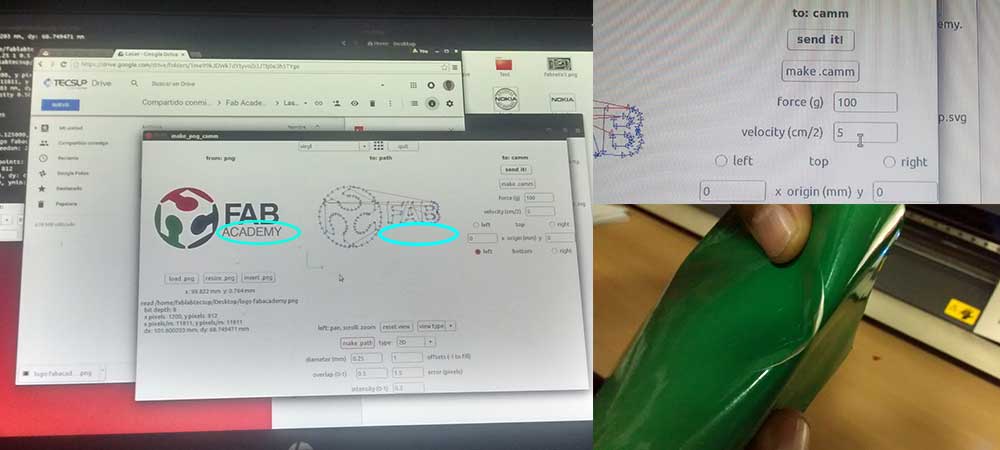
This problem occurs apparently due to the letters are gray. That color does not generate contrast enough. So, in the second try I use a black and white image.
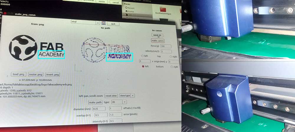
This time the small letters are cut, but the knife removes some parts of them. Apparently due to its small size.
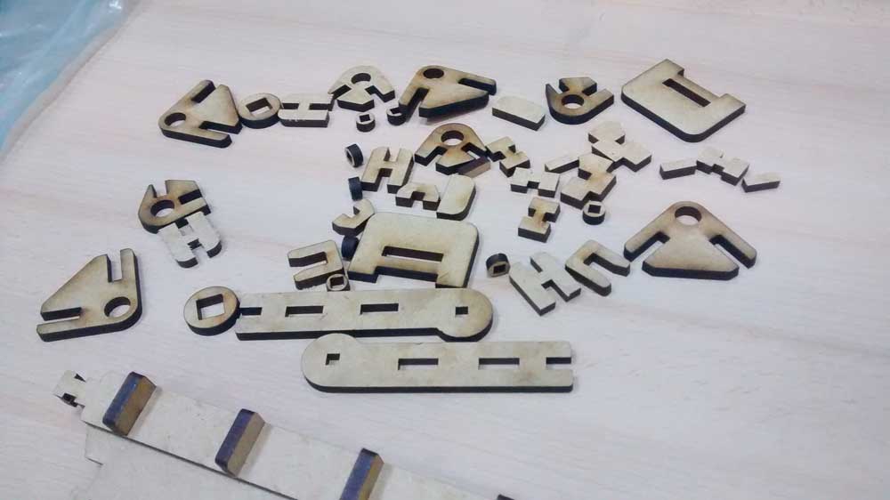
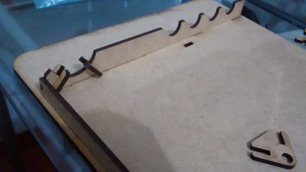
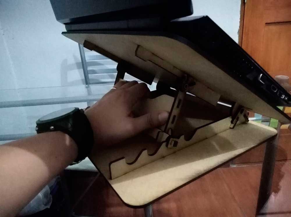
PRESS FIT CUT DESIGN (Individual Assignment)
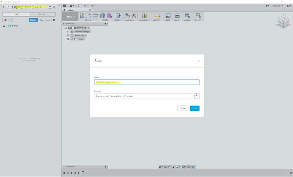
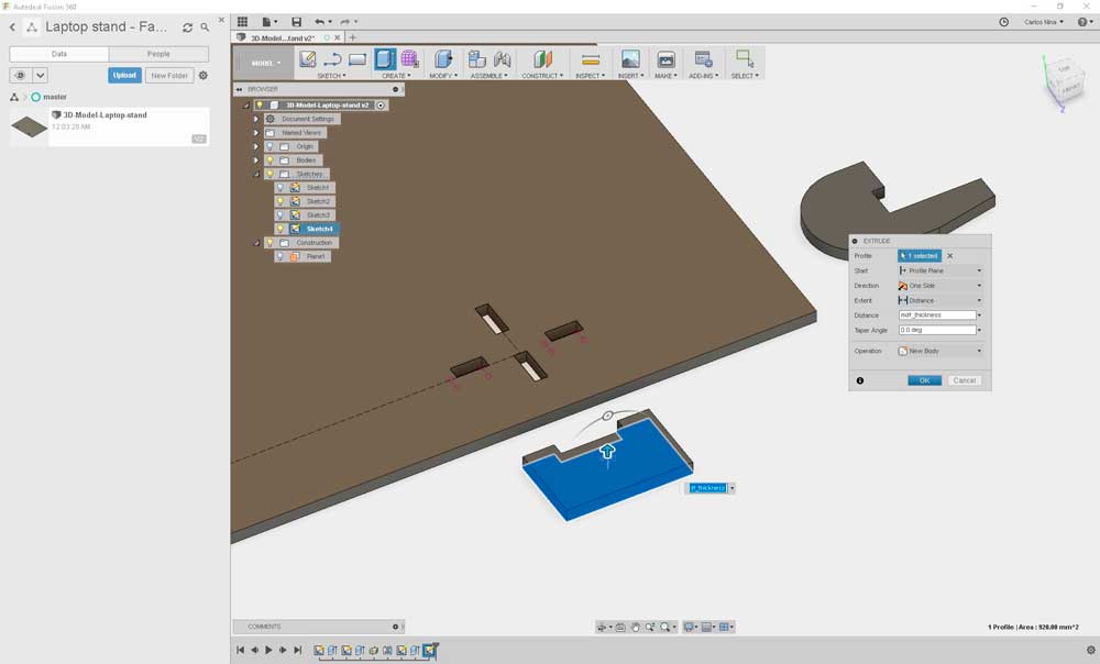
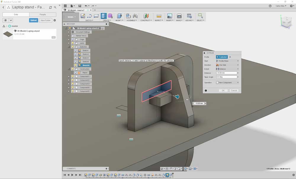
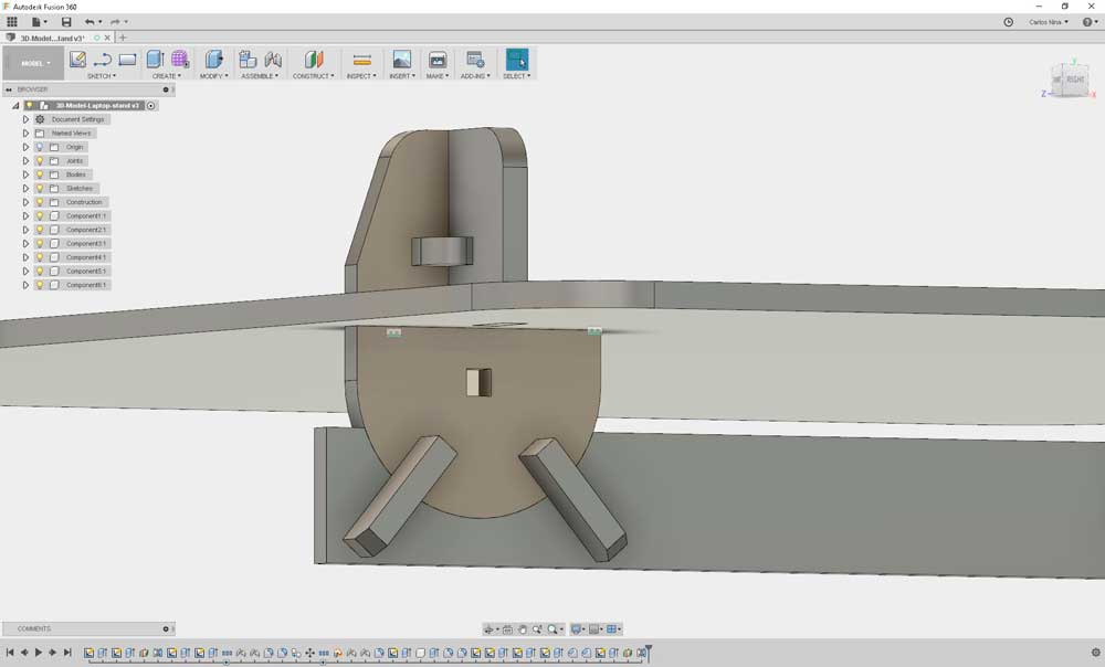
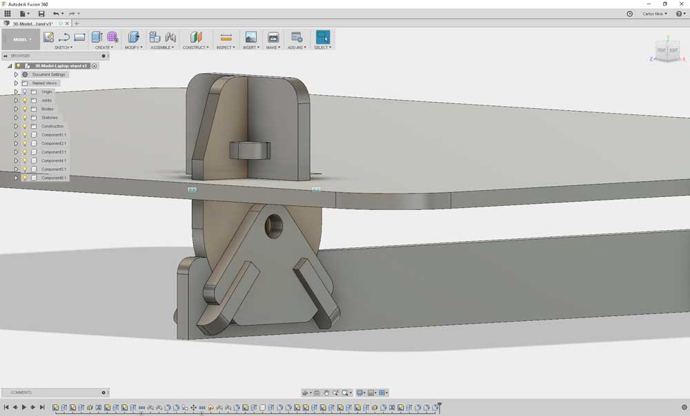
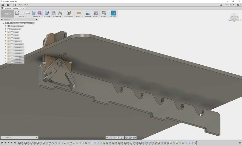
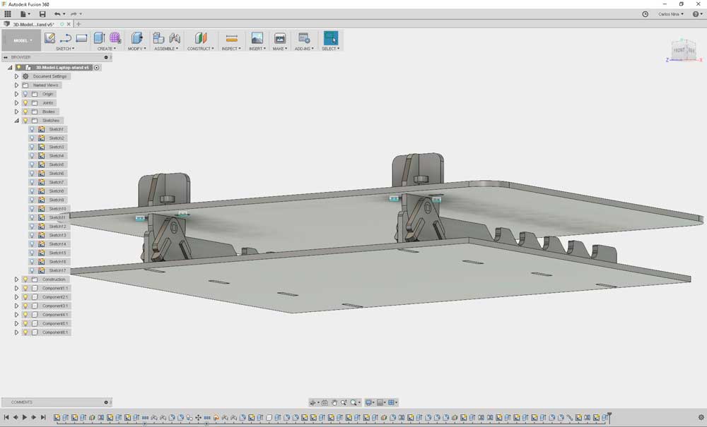
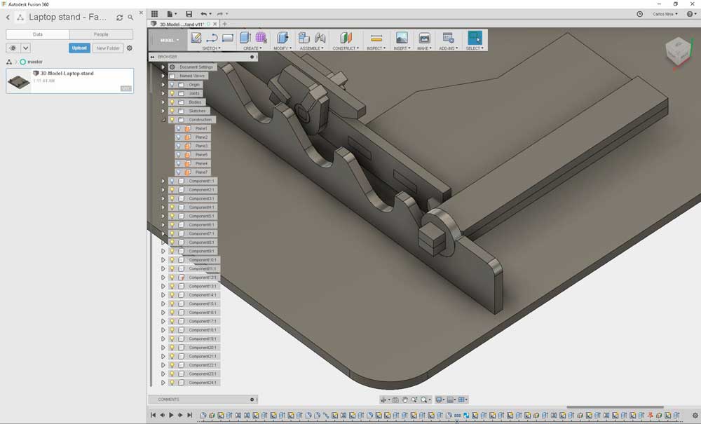
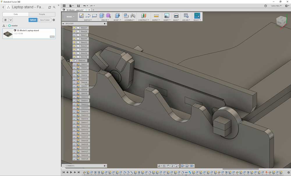
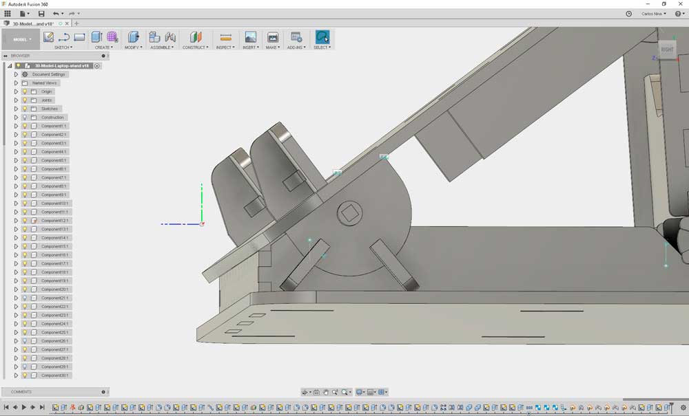
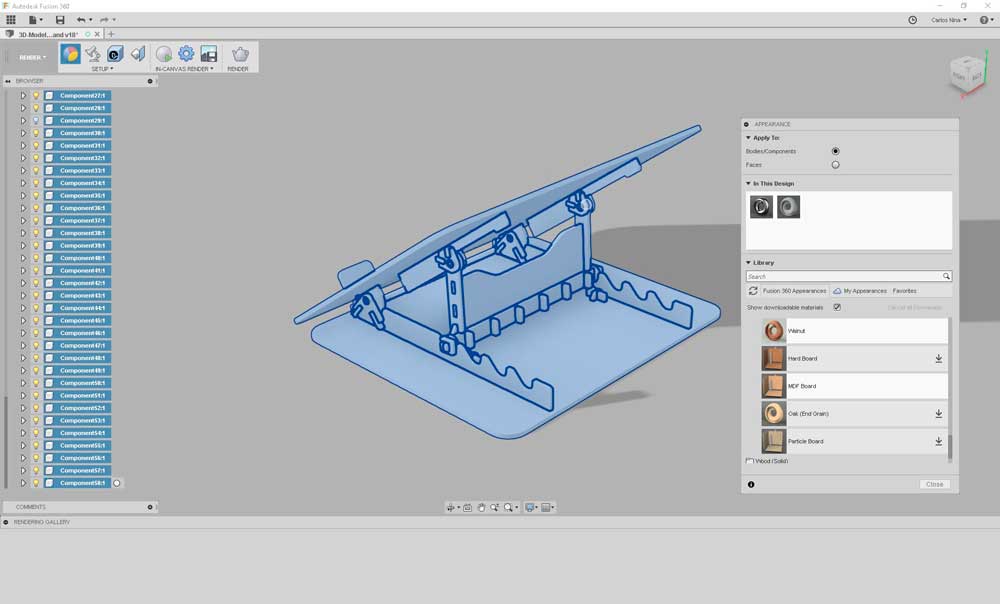
To this part of assignment, I decide to make a laptop stand. My idea is try a complex modelling and assembly (looking the model is clear that I has no intention to made the model simple). I'm not so experienced user on Fusion 360 so, I want to push me to get something "complex".
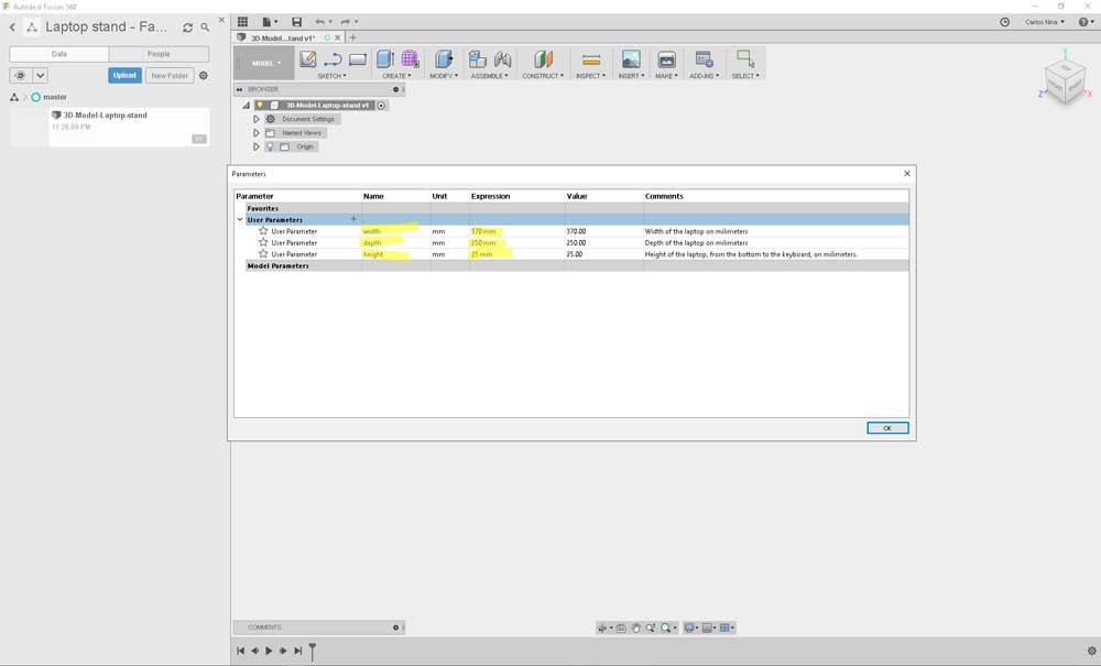
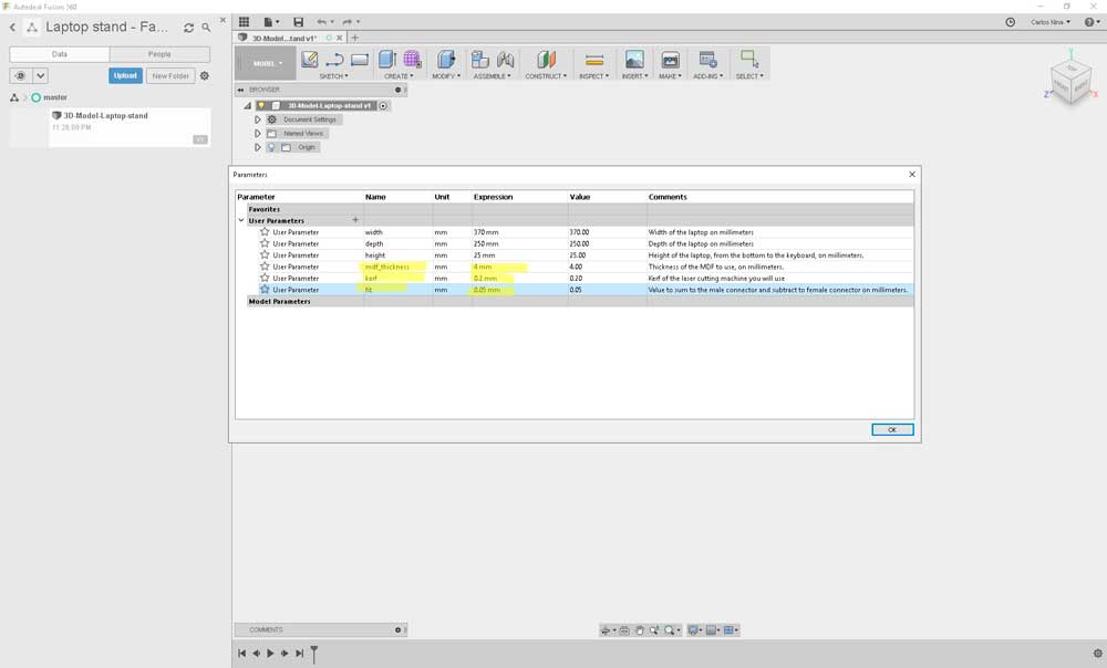

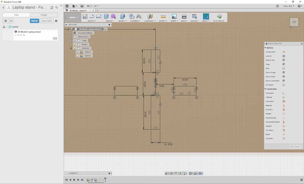
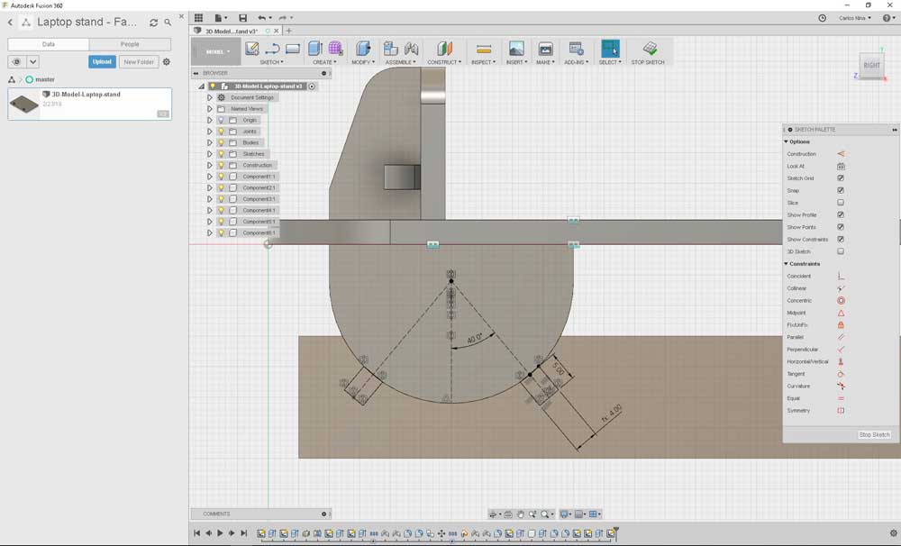
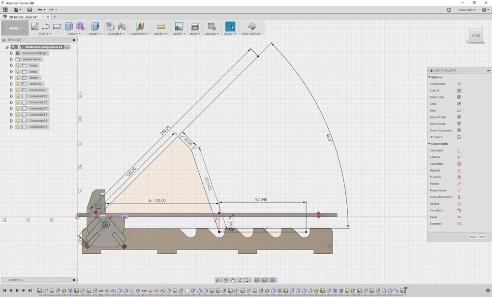
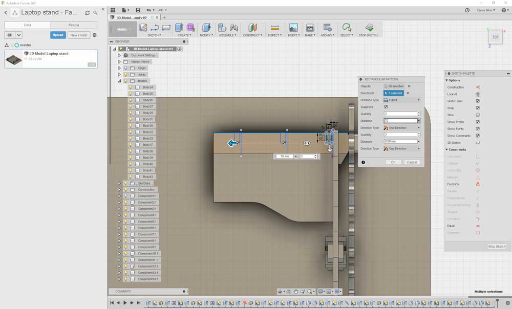
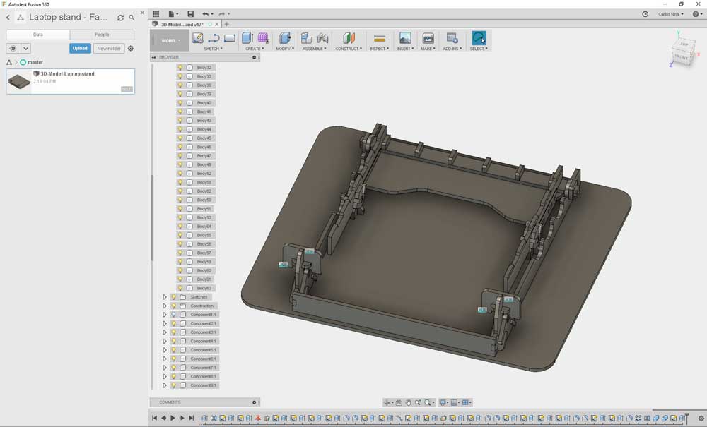
The first step to model is define parameters. These will be used on every piece of the model, especially the thickness.
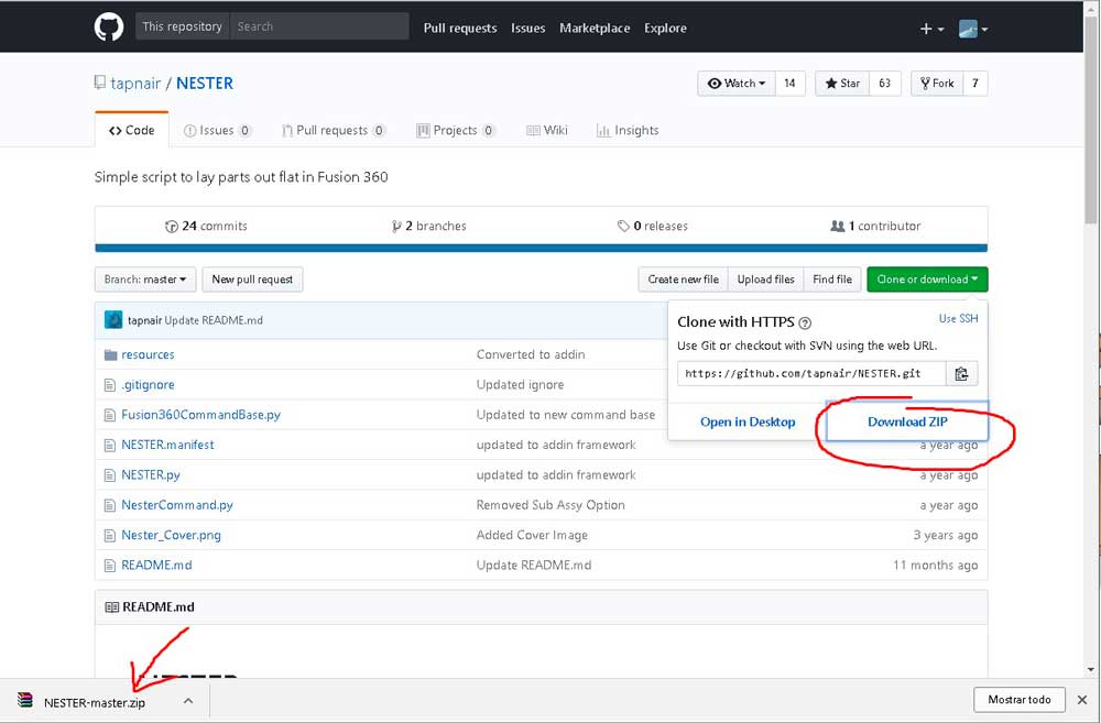
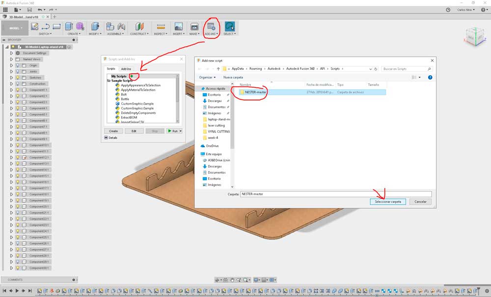
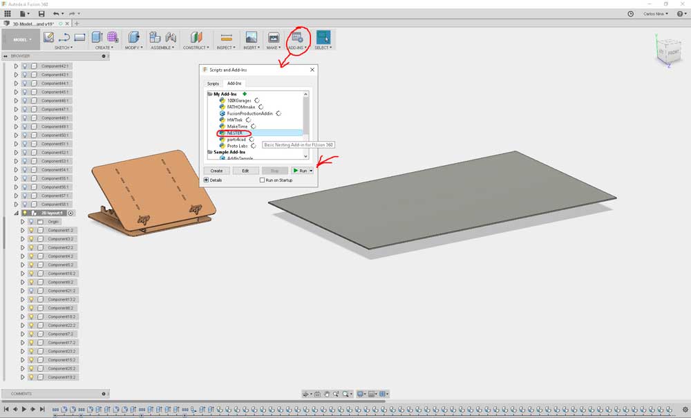
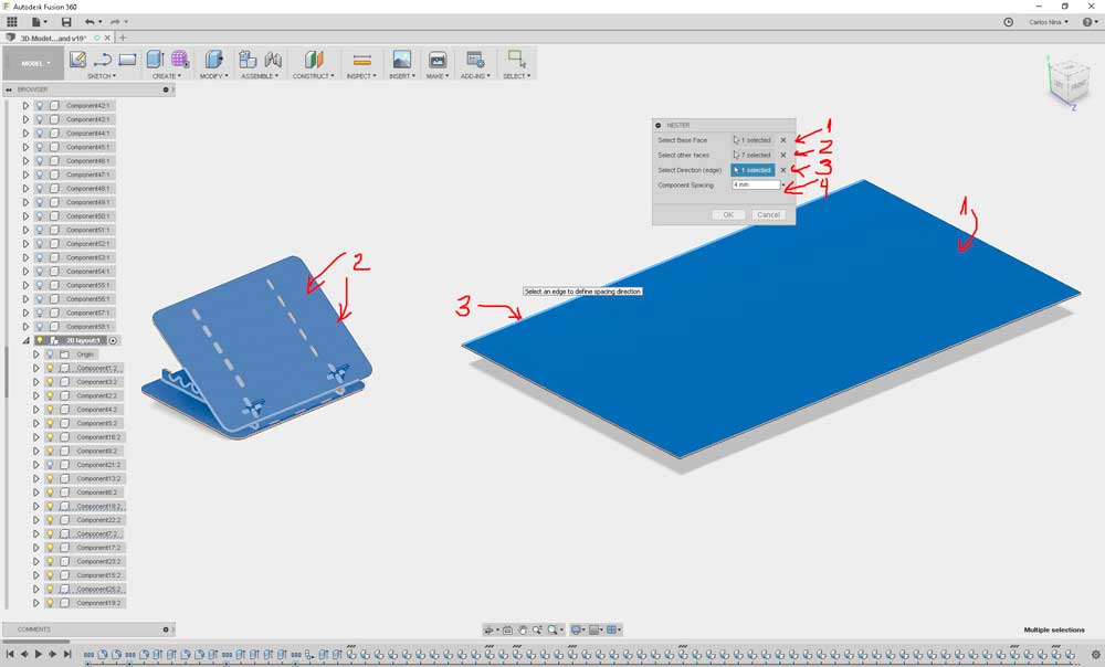
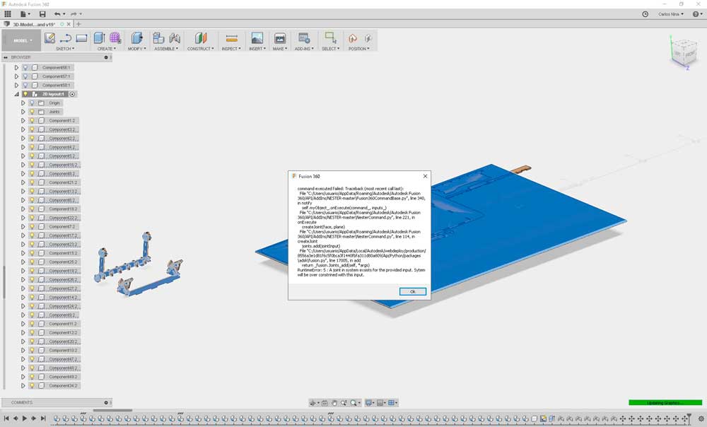
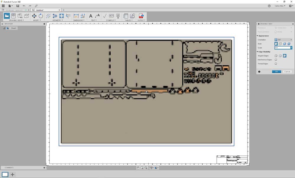
Once the model is completed, the next step is obtain the layout of the pieces on 2d, to send them to cut. Due to this task is complex just like the model, I search and found a Fusion 360's script to do this more easily. The add-in is called Nester (created by Patrick Rainsberry). Basically rotate and align pieces over a plane. The install files are here. Install instructions for Fusion 360 Add-ins are here, and a video of how it works here.
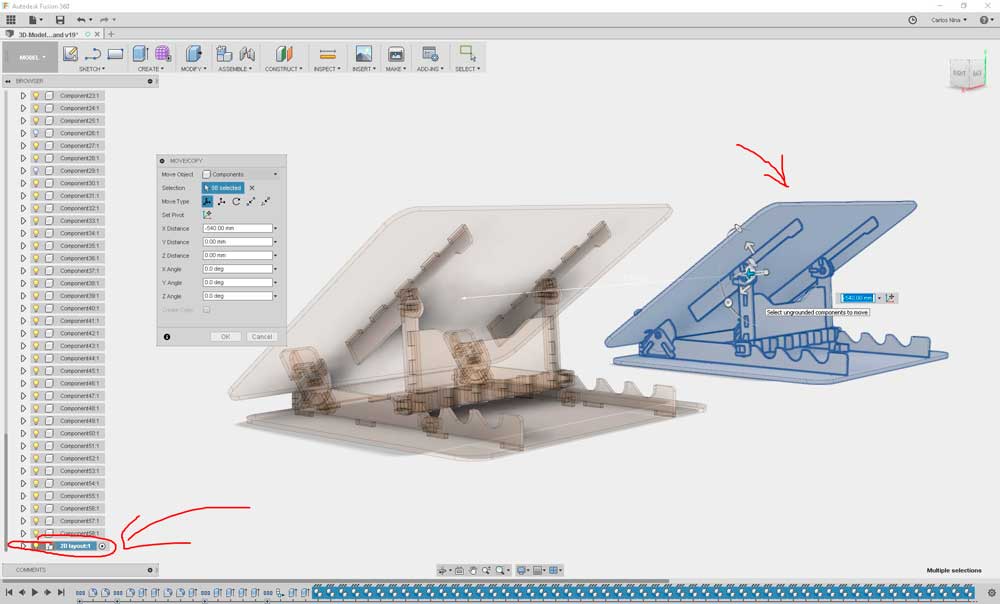
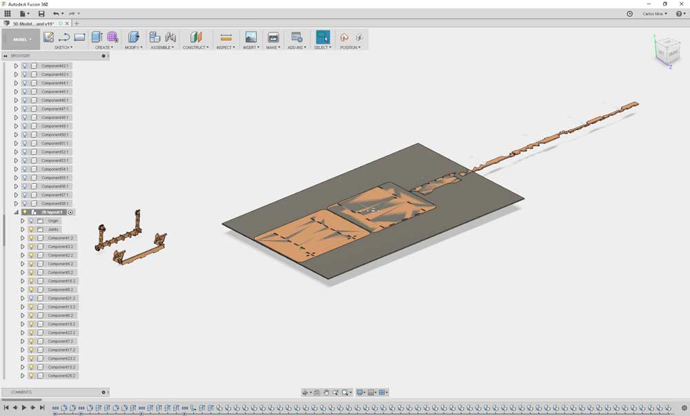
Due to the characterization of both machines taked us a lot of time. This week I will cut the pieces and make the assembly.
UPDATING
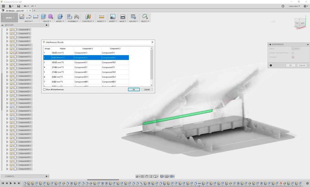
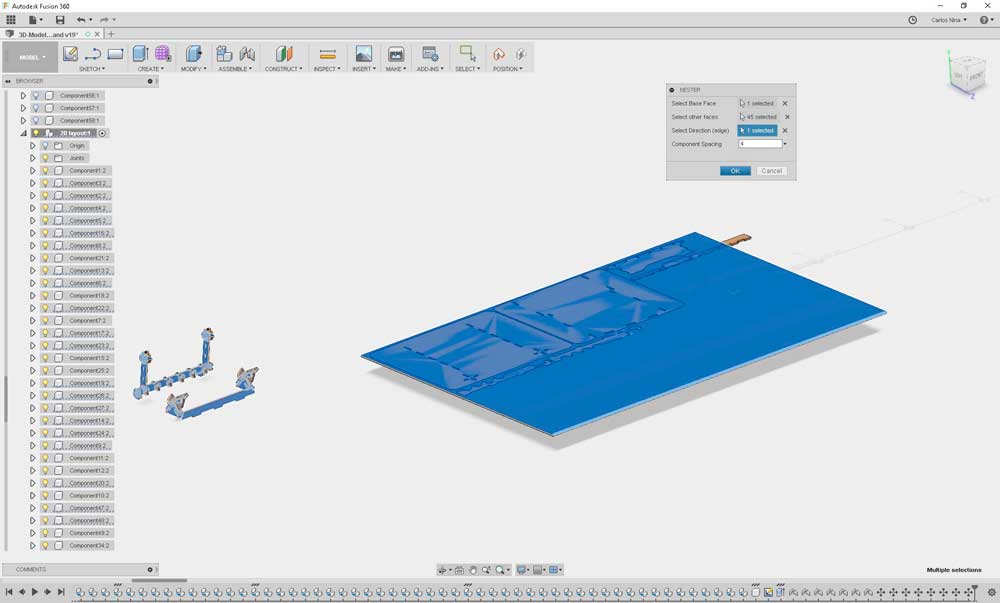
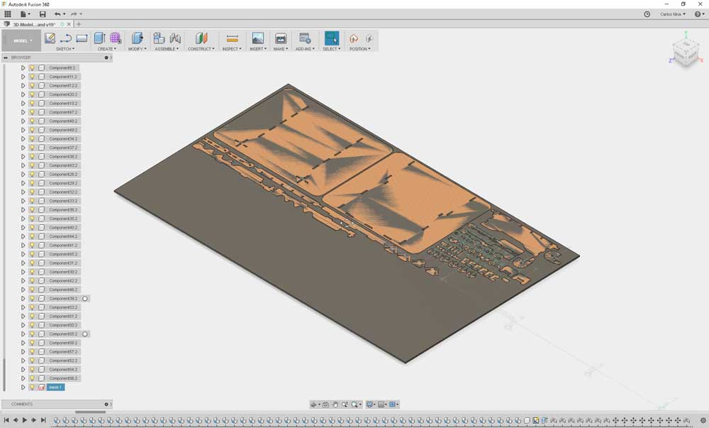
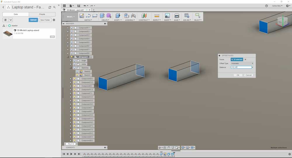
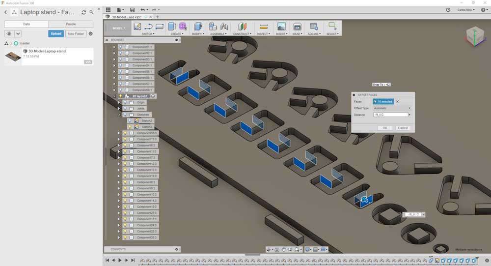
This week I finished one important task on the 3D model: set the interference fit. The previous procedure is good to obtain the pieces, but to set a interference fit that guarantee a correct press fit, we need to do something more.
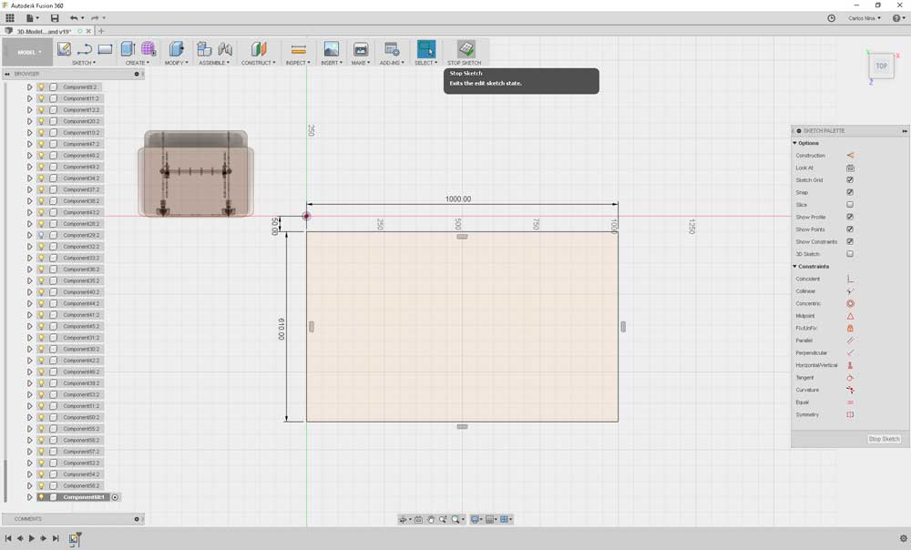
At the previous procedure, the thickness of the base plate (used with NESTER) is the same that mdf plate. This time I duplicate this thickness and later used the combine command with the option cut. The result is a only one solid (base plate) with pockets with the shape of my laptop stand pieces.
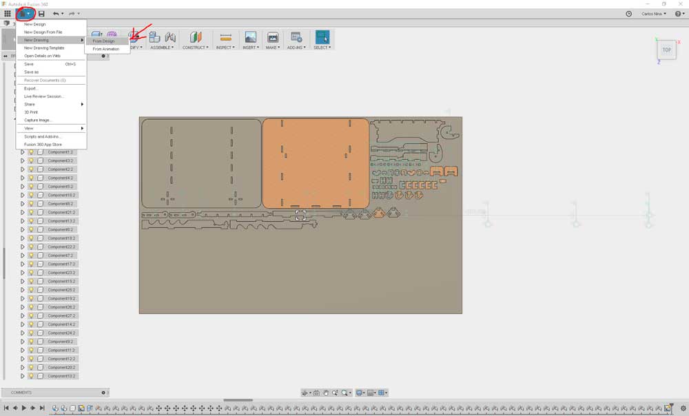
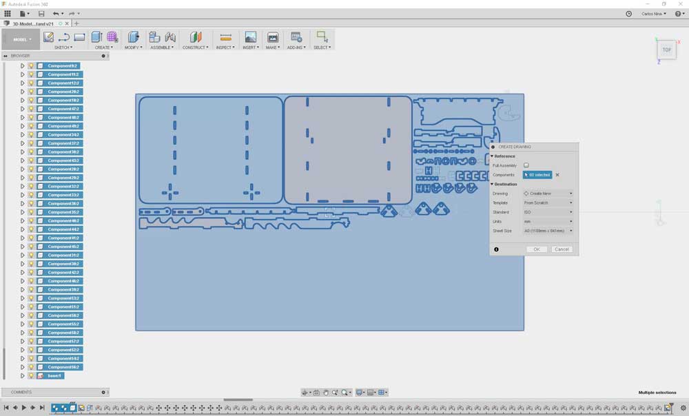
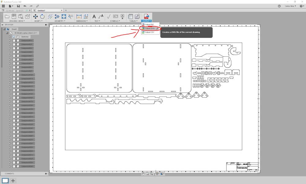
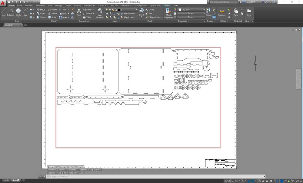
To increase or reduce some dimensions (according needs of interference fit), I used the Pull command. Once this task is completed, we can extract the profile on a dxf file. to do this, we create a new sketch, selecting the top face of our base plate solid. When, rigth click over the sketch and choose the option to save as dxf file.
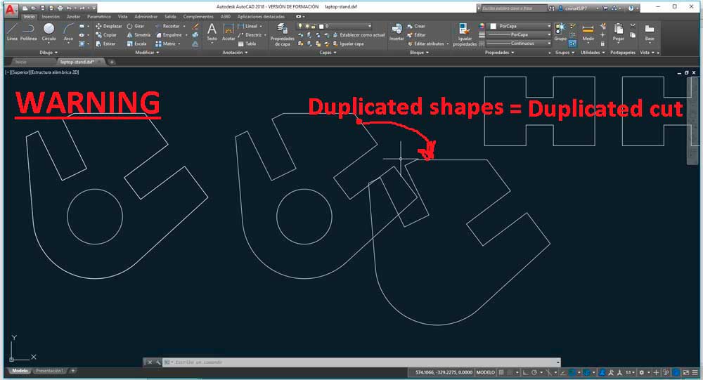
In my case (when I did the sketch), additionally project the "inner" faces with the command Project. Apparently this causes duplicated lines on my dxf file. This is an undesirable thing, because a duplicated line makes de laser beam on the machine pass two times for the same place. So, you need to check this, before cut.
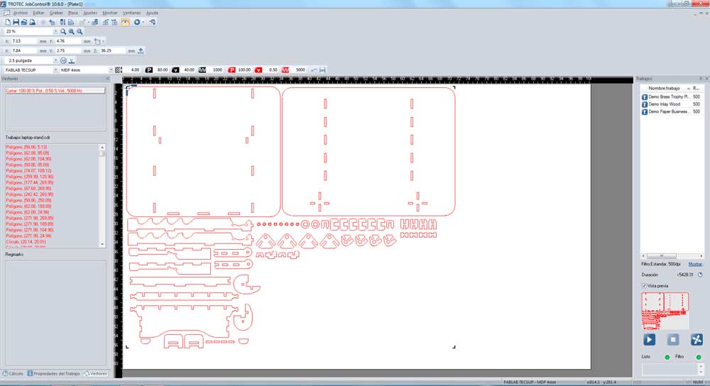
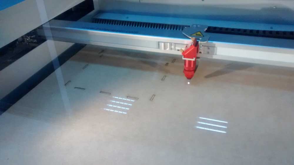
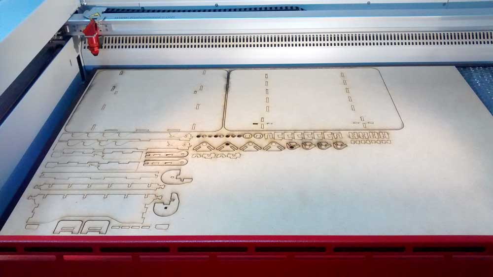
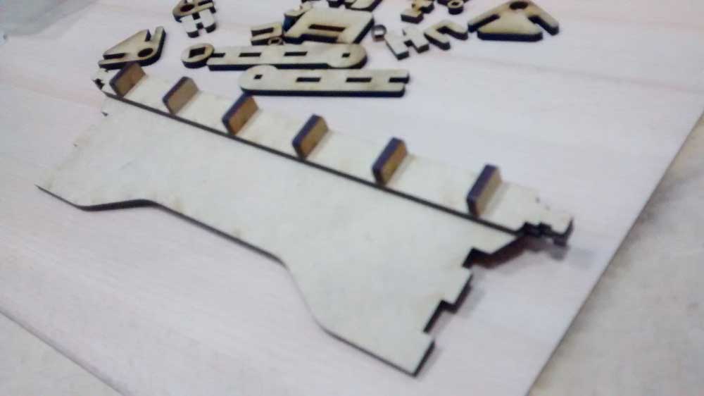
Finally, the cutting.
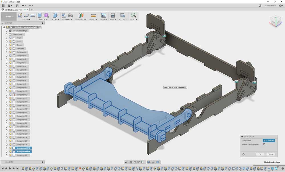
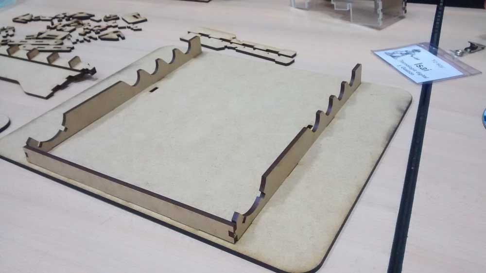
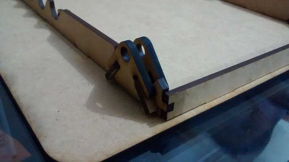
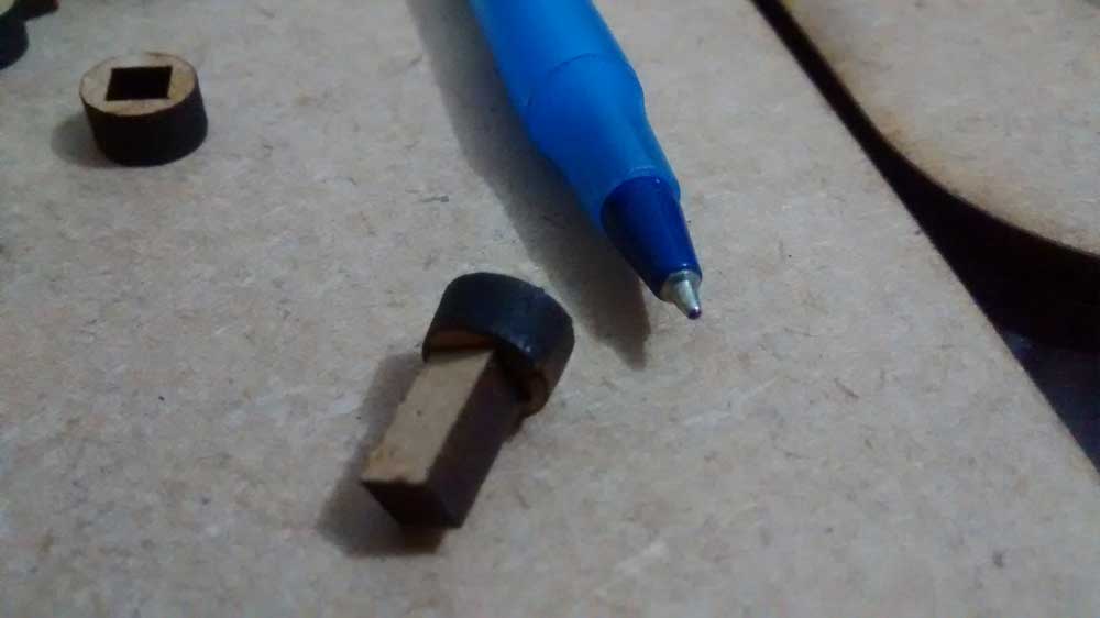
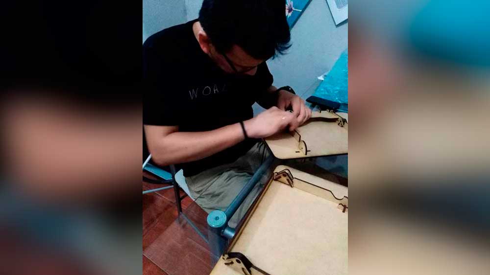
The assembly process
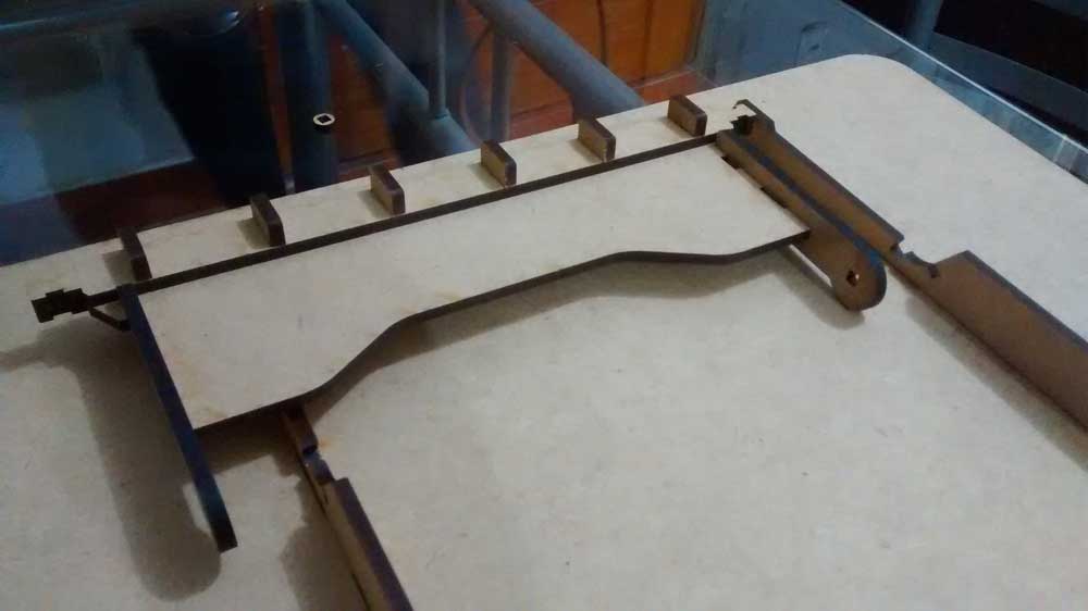
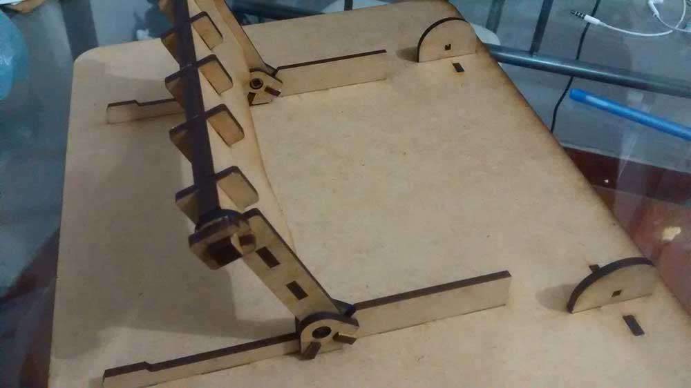
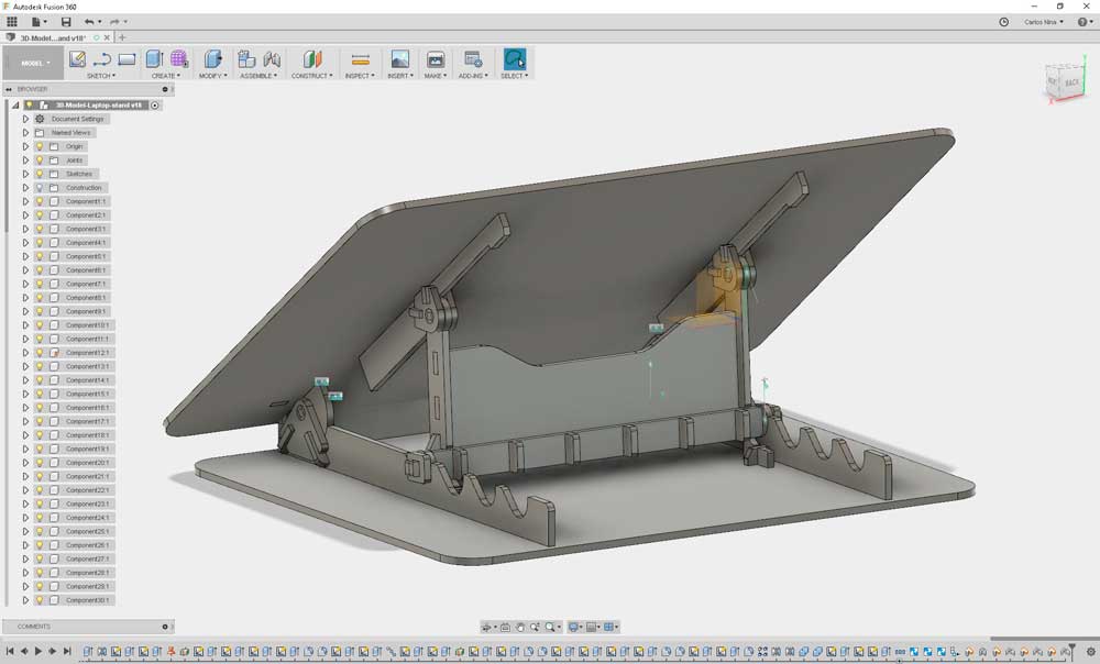
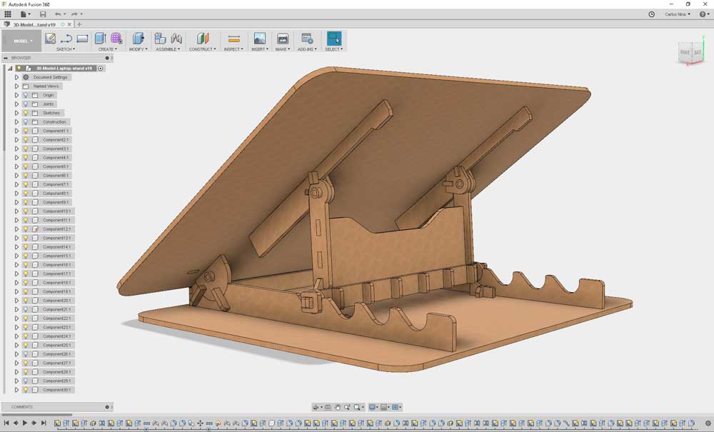
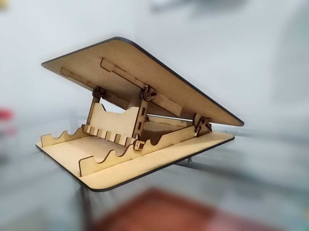
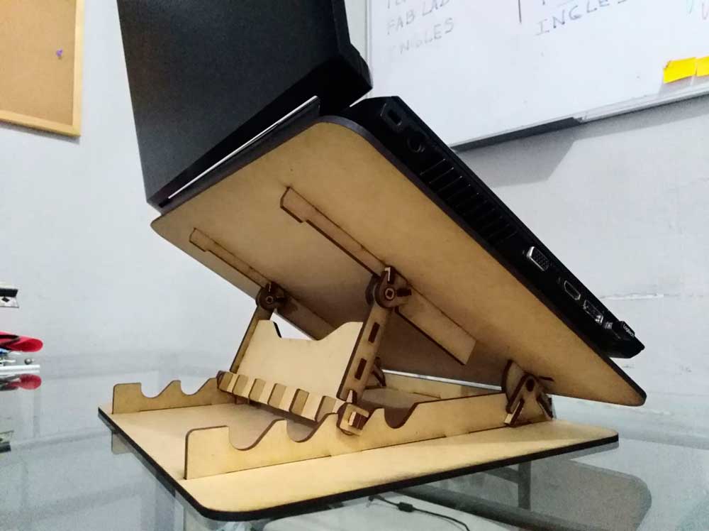
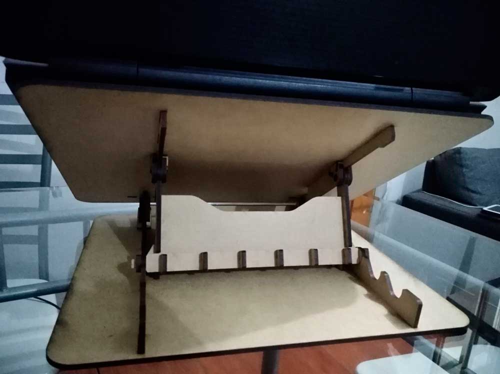
The final result
To get the files for this assignment, please visit my repo on Github: https://github.com/CarlosNinaOchoa/fabacademy2018/tree/master/Week-Assignments