Computer-controlled Cutting
Assignment
- Make something big
File
Design
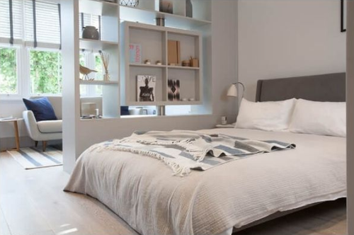
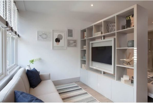
I decided to make something for a new apartment I'm moving to in the summer. When trying to find an idea I searched the internet and found a bookshelf which also functioned as a room divider, which makes it ideal for small places where you would want to make use of every single square feet.
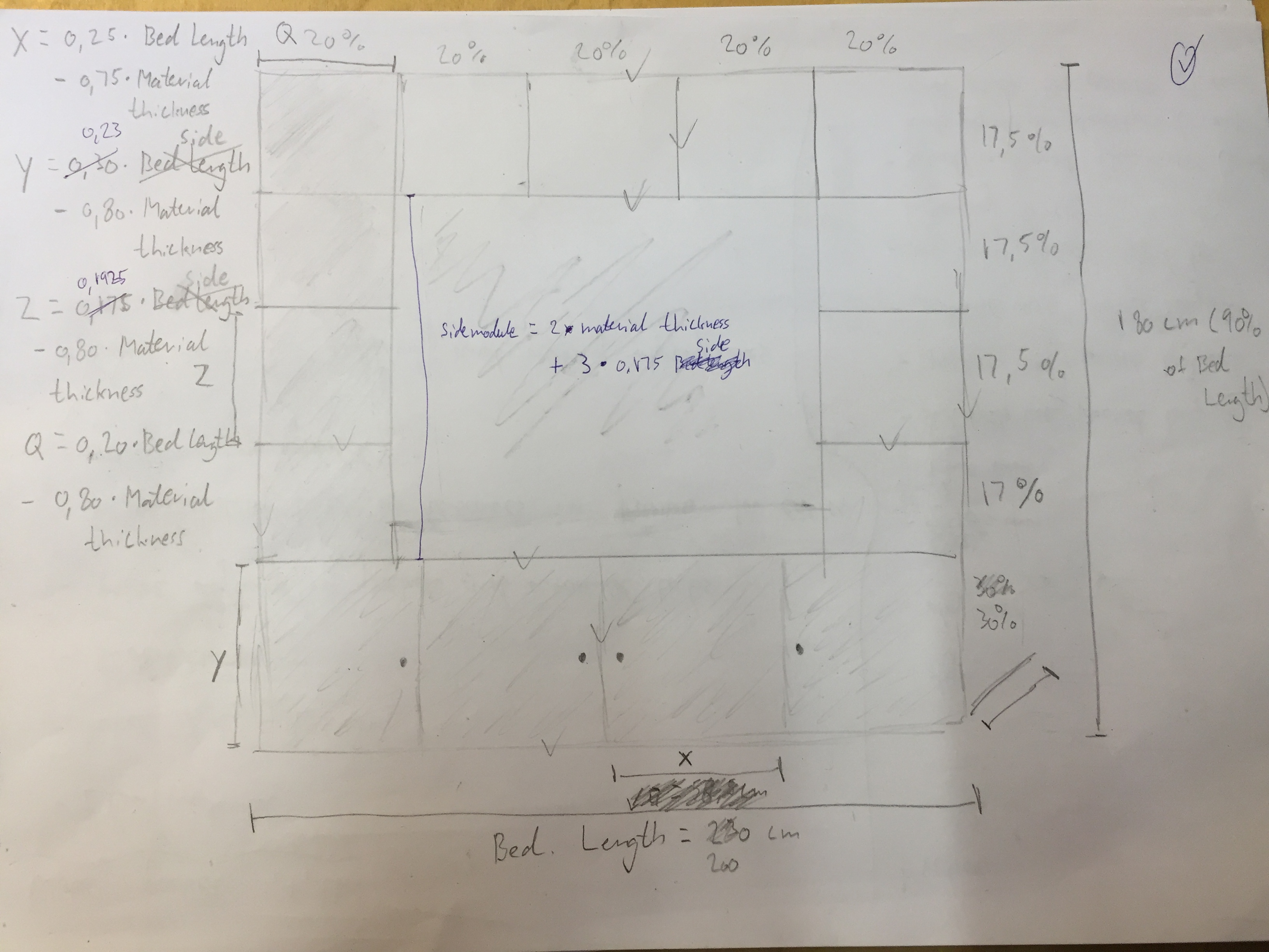
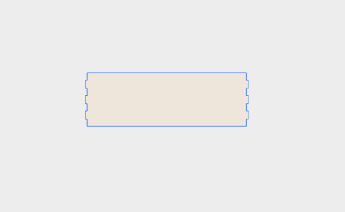
First thing I did before using a 3D modelling program, was to make a sketch where I specified every single length that I needed so that I could easily create a parametric design afterwards. The main sketch which you will see underneath contains most of the dimensions made as an equation in relation to the length of the bookshelf which I have called "bed length" because everything is to fit the size of my bed as in the picture I found for inspiration. This is especially important later when making the parametric design, since things will not lose their position when changed in length because the length is always a percentage of the line that the length in connected to.
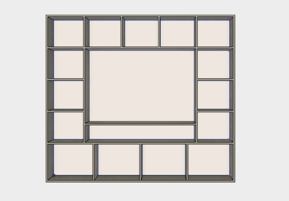
From the sketch I applied everything to the 3D modelling software Fusion 360 where it looked like this:
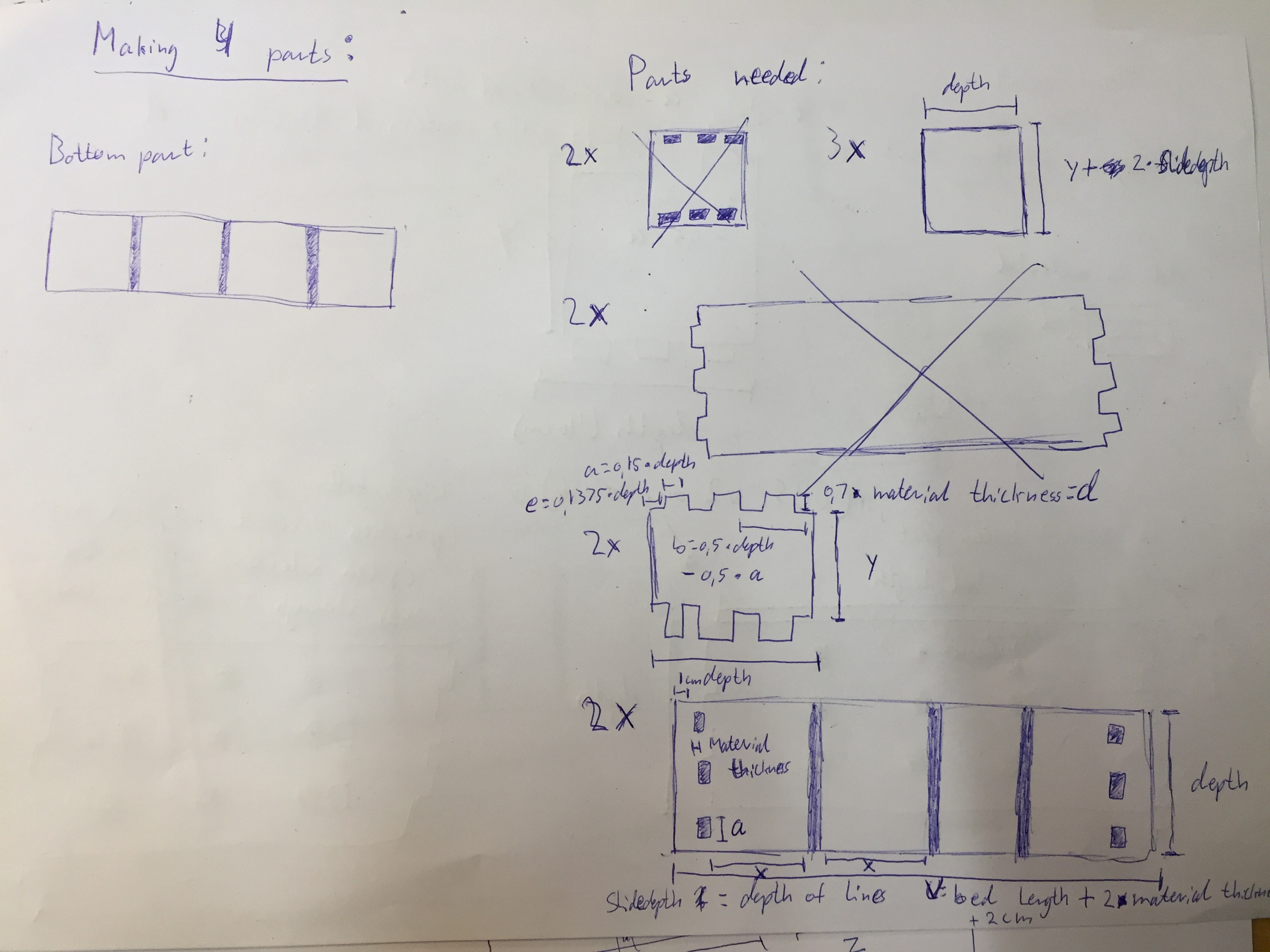
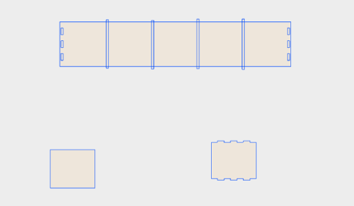
After this I had to specify how I would assemble all of the parts which is very important since this model is fairly big so there is a lot of room for mistake. I wanted to make a design that would only be held together by gravity with no use of glue or screws. I did a lot of thinking and a lot of sketches but would always end up with a design where I would have to bend something into place, which is not what I desired. I took some drawings to the local lab and was given the idea to divide the shelf into smaller modules. Making each square into a module itself would use a lot of extra material which is why I decided to make four modules instead: One top module, a bottom module and two identical side modules. The outer case of each module is assembled with tabs and pockets so the joints won't be visible. Each shelf will be sliding into a drill.
Once I knew how I wanted the design to be, I planned the 3 dimensional model out as 2 dimensional drawings which the machine would able to read.
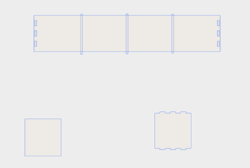
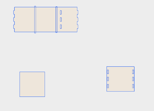
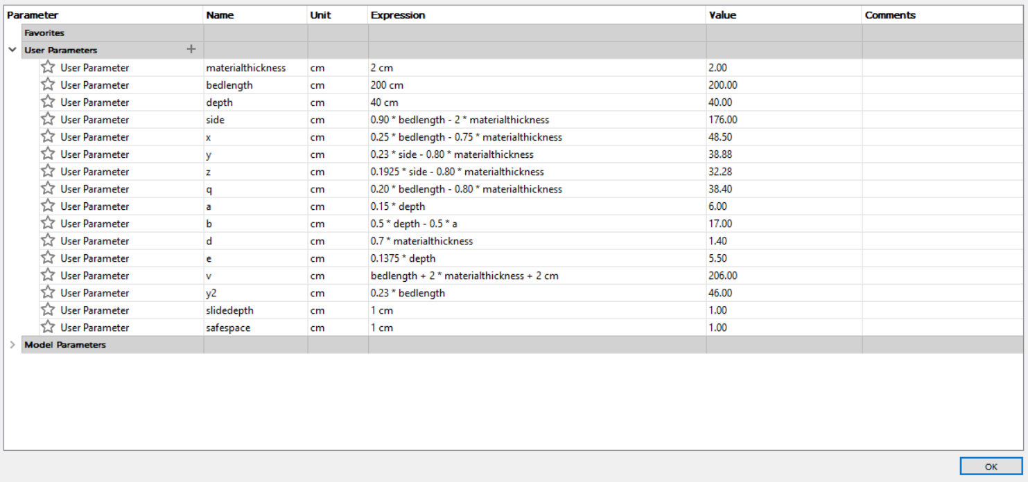
Underneath you will see all the parameters I had been using which, apart from the things already mentioned, enabled me to have a standard in every drawing I made. The tabs and wholes is therefore placed the exact same way in every module because everything relates back to the bed length which is what the shelf will be standing next to.
The design I have made has both good and bad things to it. I'm not planning on using any glue or screw, but I think I will have to use dowel pins to connect each of the modules. Also because the taps and wholes are made so that gravity works towards pressing the taps into the holes, I will be having some overlap of material in the sides of the top and bottom modules. The big flaw of the modules design and shelves that are sliding into a drill is that it will be fairly easy to rearrange the design once settled.
VCarvePro
VCarvePro is the name of the software used to specify how the machine should cut your design file. First thing I did was to type in the default sheet size for the wood we were going to be using. The size is 2400 mm x 1200 mm.
For my file I wanted the machine to do three different things when cutting the wood. Make a slide with a depth of 1 cm, pockets for tabs with a depth of 1,4 cm and lastly to cut the outline. Therefore i had to make three different toolpaths with each of the specifications. When the right tool and cutting depth has been chosen, simply click on the drawing to apply the settings to the desired part and hold down shift for multiple selection.
When being taught VCarvePro and basic CNC milling concepts, I was introduced to the concept of dogbones. Because the bit of the machine is round, you can't make perfect squares in the material. Instead you will end out having round corners which you can't fit square shaped material into. This becomes a problem with the tabs and pockets I will be using which is why I will be adding the "dog bone" shape to the squares. Underneath you can see the concept visualized.
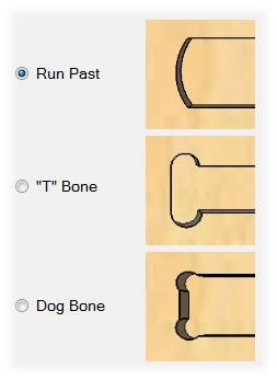
The first example above is the imperfect square shape and "T" bone is yet another design. Luckily dog bones is a feature inside of the VCarvePro software which makes it easy to add to the design. On the design files I have also made the slide drill as a square that goes past the line of the outer shell of the design. This is done to make sure that the machine will drill all the way through and not make a rounded square where I won't be able to slide my shelfs into.
Testing the machine
A part of this weeks assignment was to test the specifications of the machine but because of a fire in the CNC machine that we had in our lab described by my fellow student Claus on his page, things got a bit complicated since I was not able to use the machine. Instead we got the opportunity to go to another place and use their machine, but only for a limitied time. Later during my final project I got some time to make some tests with the machine in oure own lab since It was working again
The testing I made was to assure that pockets would be fitting nicely with tabs. To do this we need to use allowance which is the distance the machine will alow for example a pocket to be bigger then the shape that is drawn originally. This allows some space for fitting tabs into the pockets.
We found that -0.2 allowance what the perfect amount for making pockets. It would be tight to get into place, but we would rather have a tight structure than a sloppy one.
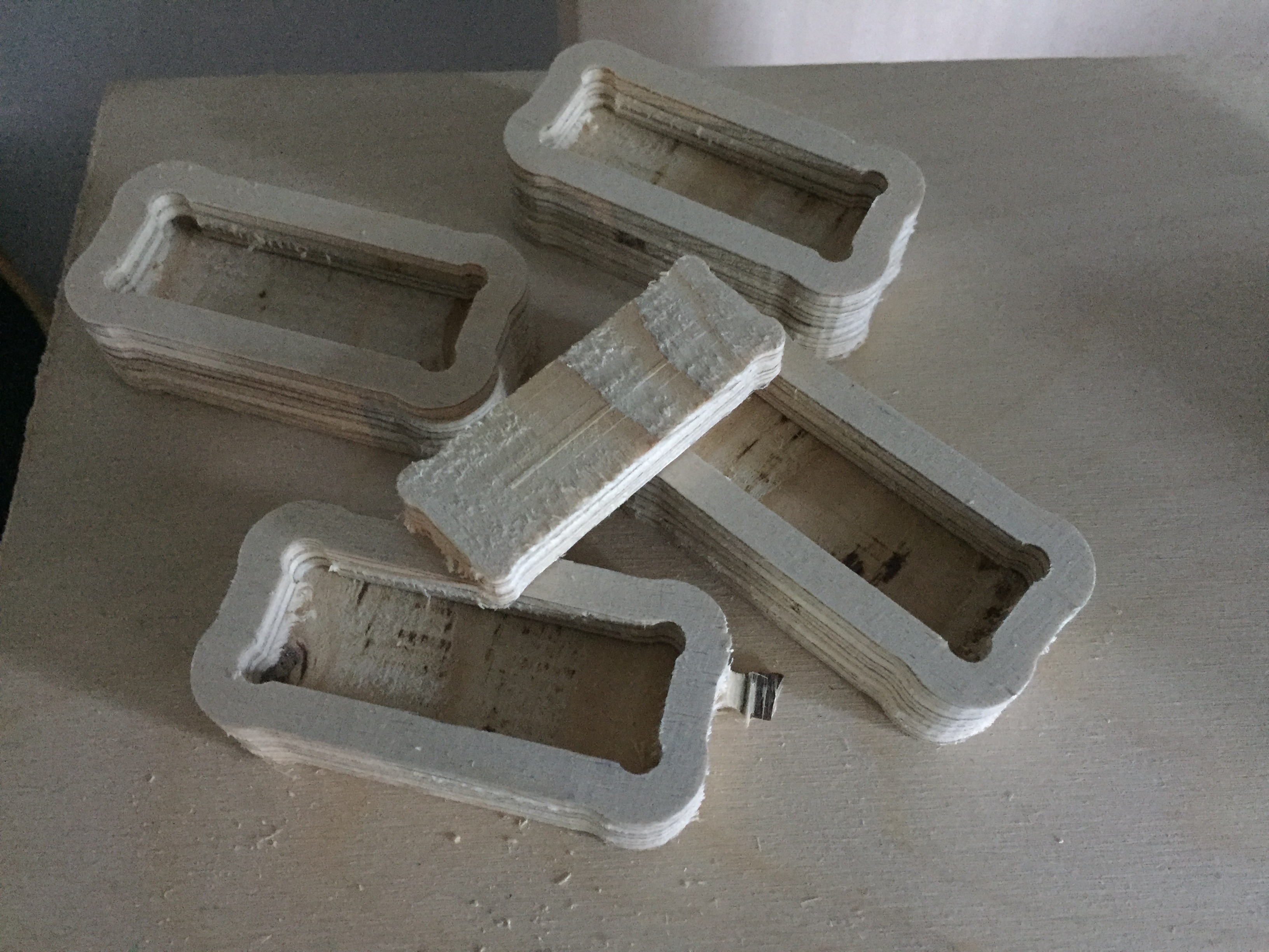
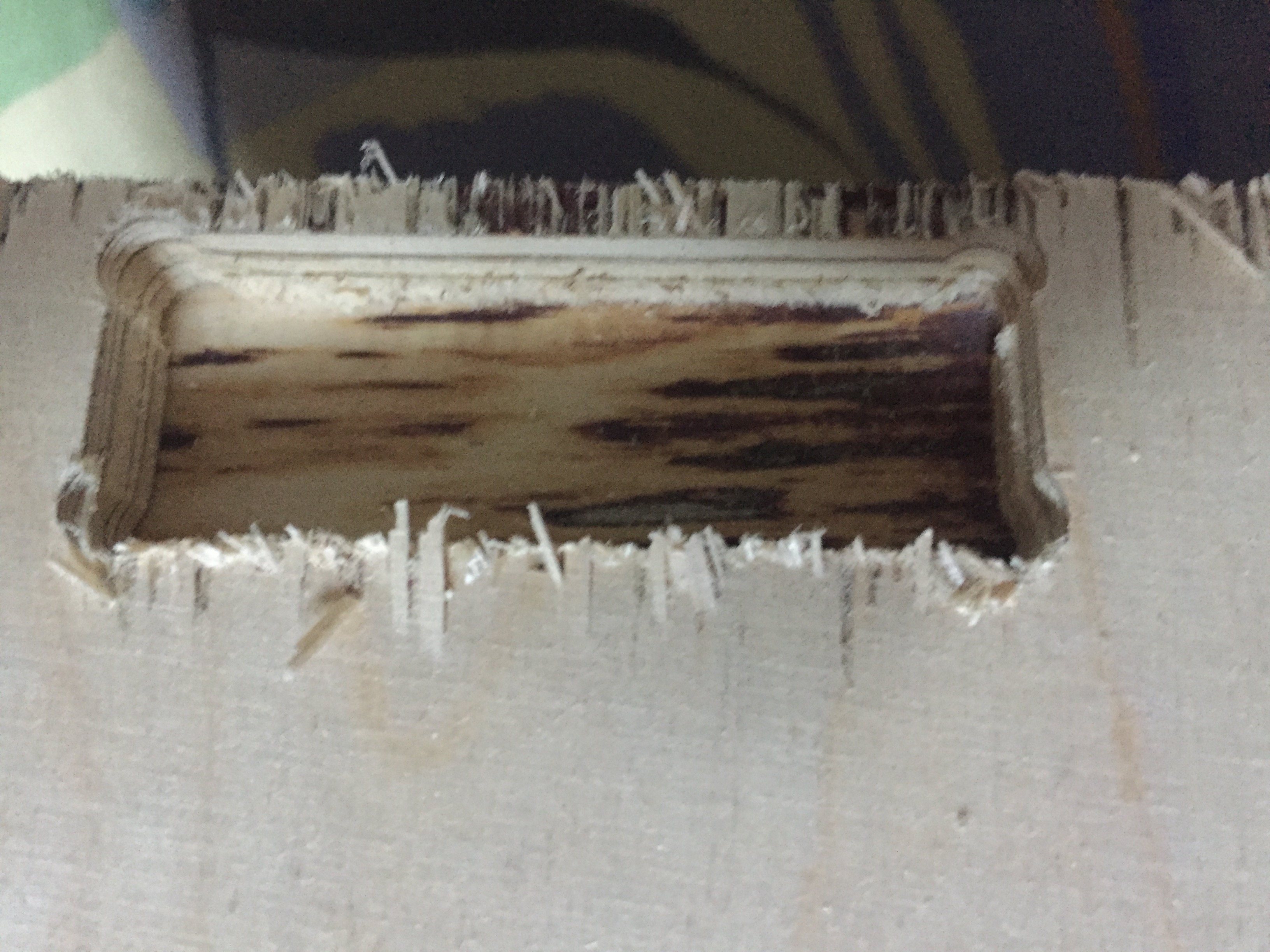
Another note which we found to be very importaint is upcut vs. downcut bits. Up- and downcut indicates to which way the leftover material is being moved. When using downcut bits there is no need for tabs to hold the wood in place since the leftover material will simply pack around it. Another importaint thing is that the edges for the material will get a lot nicer when using downcut bits (used for making the shelf itself further down on this page). This is an example of using an upcut bit where a lot sand papering has to be done:
Assembling
Before milling one of my big modules, I decided to do a small test to see if everything was going to fit. A guy called "Mads" who was in charge of the machine in the other place introduced me to the concept of tolerance when assembling parts of wood like this. Before cutting any of my big parts I decided to do a small test. The test I made was with no tolerance, which made it very hard to assemble. With a lot of force I managed to slide the shelf into place, but the top part was unable to go into place. It was simply too tight.
After the test I spoke to Mads about the results of test. He was confident with the machine and his knowledge about tolerance to already cut one of the bigger modules.
In Vcarve where it is possible to make paths for everything you would want to cut, we outlined the whole job.
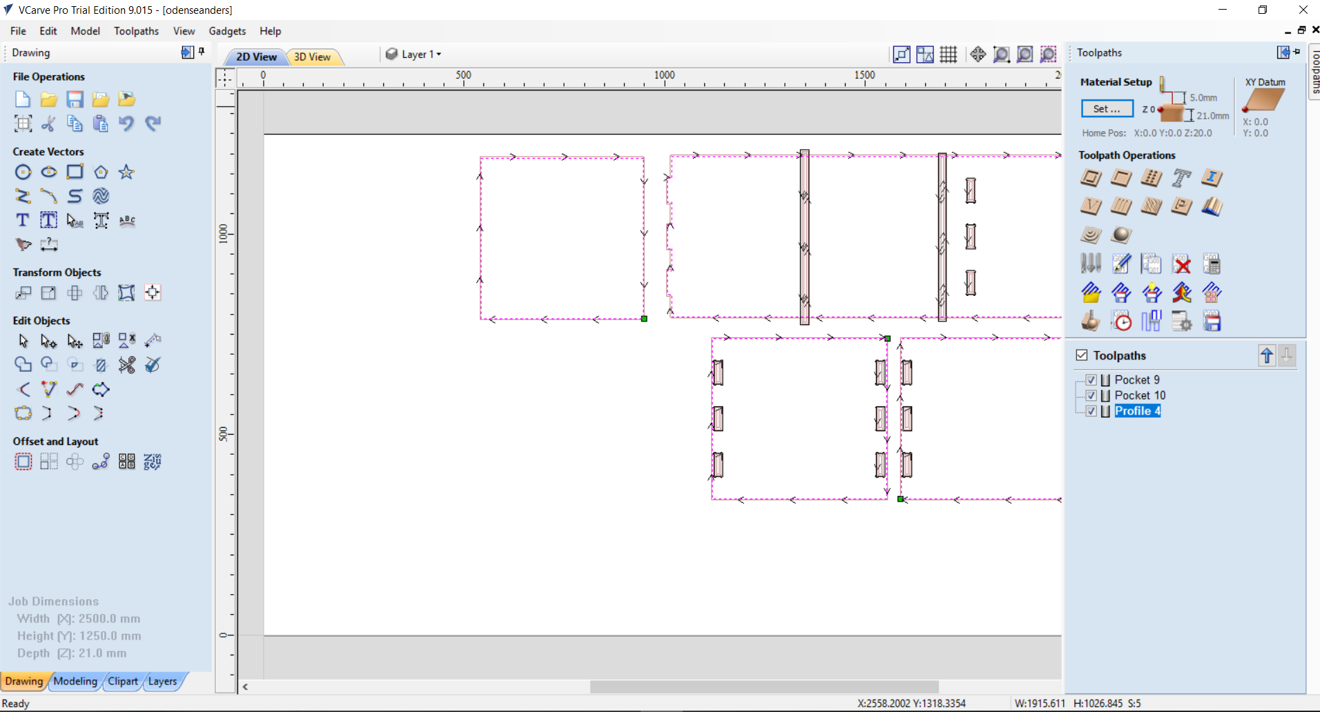
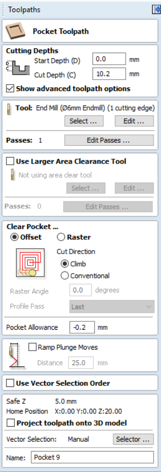
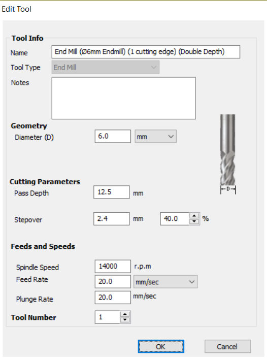
With my shelf we made two pocket paths for, one the pockets and also one for where the shelfs were going to slide into. Last path is a profile path to cut everything out. For the pockets we used -0.2 mm allowance. The bit was the same for all of the three runs, which was a 6 mm downcut bit:
Next we were letting the machine do its thing which did take some time because of the job size.
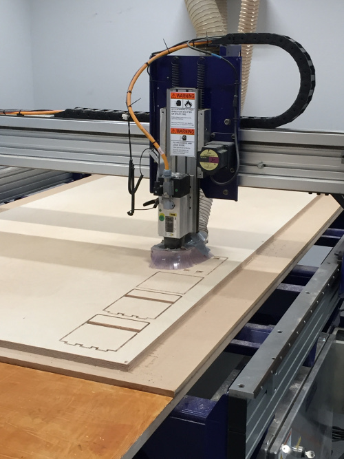
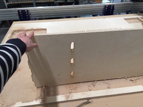
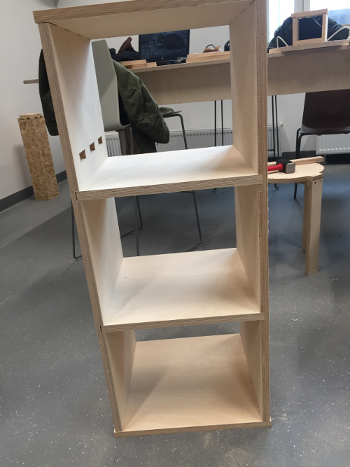
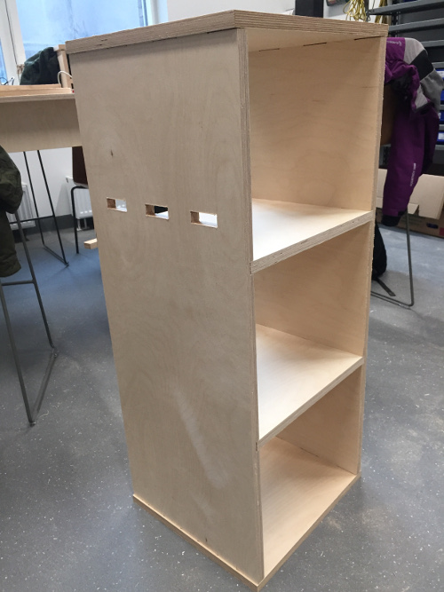
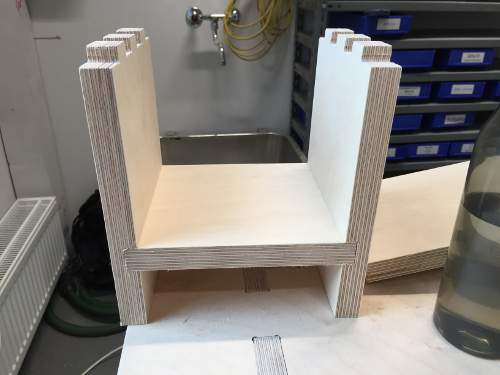
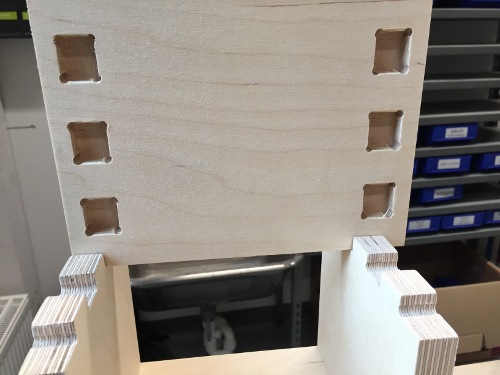
Everything was still a bit tight when assembling everything, but not as tight as when I was trying to assemble the test part. I still had to use a hammer to put things into place, but once assembled things won't go anywhere. As shown in the pictures above everything looks as it was supposed to in the files and I'm glad the parametric design worked well. Before I install the module in my apartment I would just have to run some sandpaper over it.
Because of time management I was only able to cut one of the four modules I had planned. I would have to dothe rest some other time but because of the module design, I can still use this one part alone as it is.
Thoughts
At the end of this week my feelings about the CNC is a bit mixed. I’m happy that we could go to another place and use their machine, but because of the limited time we had with the machine I was not able to learn about it’s specifications and get confident using it myself. This is something I would have to do once the machine in our lab is running again after the fire accident.