Week4
Computer-Controlled Cutting
Laser Cutting and Vinyl Cutting
Assignment:
Characterize your lasercutter
You can see the complete documentation of group assignments on the opendot website at this LINK.

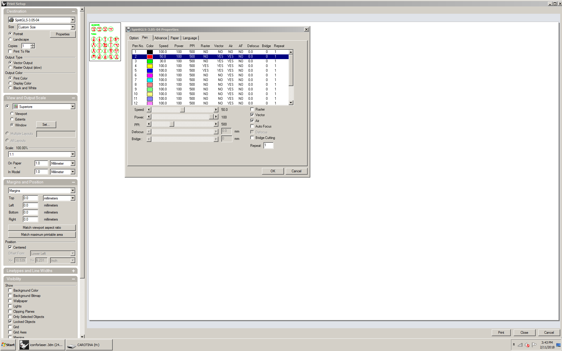
For the characterization of our lasercutter we started by cutting a file dxf that contained an interference test. We cutted everything with a Spirit GLS machine and using the print driver from Rhinoceros. We use this setting for cutting and engraving: Material: Playwood 4mm Engraving settings: Speed 100%, Power 50%, PPI 500. Cut Setting: Speed 2.5%, Power 100%, PPI 500.

For the engraving test we created a vector file with Inkscape which contained a series of grayscale squares. The idea was to export in jpg format and import into Rhinoceros to understand how the machine behaved in the raster engraving of jpg images. This was meant to understand how much the raster engraving varied with speed. Always leaving the power unchanged. This experiment failed a lot because we could not figure out what was the right setting to let the laser image read the jpg in the best way..


Icon set for Final project: Lasercut Test

For my final project I designed a series of icons designed for laser cutting, you can read more at the end of this page. What does it mean? Which have been designed starting from a continuous line so that an engraving vector can be managed: to allow a high readability even if very small, to minimize engraving times.
I reproduced the file in two different sizes: In the first (the smallest) the icons are 10 mm in diameter. In this file I managed the vector engraving with two different parameters: Speed 30%, Power 100%, PPI 500 for engraving edges and text - green layer - and Speed 50%, Power 100%, PPI 500 for engraving pictograms - red layer -. In the second file the icons are 15 mm in diameter and in this case I tried to increase the speed of vector engraving using 60% for the text and 70% for the pictograms.

I'm very happy for this result because the icons maintain good legibility even from very small, the laser allows us to get very high details that printed on paper would be lost. If you want to try also the icons are available, in .dxf versio by pressing the button below.
Cut something on the vinylcutter

For this exercise I decided to test if the icons that I designed for my final project, to see if, despite being monolinea, they could work well, even if cut with the vinilcutter. I modified them in inkscaper to be able to give thickness to the stroke. I wanted to understand how much the dimensional limit was and whether they would work in positive and negative. it was also interesting to understand which materials the vinyl adhered to better. Now I would like to find a versatile paint that goes well for different materials, to be able to use the vynile as a stencil. it's interesting because from a single icon, then from a single file, three different views can come out. For cutting, I use CAMM1-Servo GX-24 Roland Machine with Cut studio software and Inkscape.
 Starting this machine is quite simple,
after turning it on, you need to position the roll (aligned in the middle) after raising the lever on the back, position the sheet following the markers and then move the trim sheet wheels. Now locks the lever. Choose "roll" on the screen and scroll the sheet. Now hold "origin" until "origin set" comes out.
From inkscape you can send directly the file in cutstudio.
Starting this machine is quite simple,
after turning it on, you need to position the roll (aligned in the middle) after raising the lever on the back, position the sheet following the markers and then move the trim sheet wheels. Now locks the lever. Choose "roll" on the screen and scroll the sheet. Now hold "origin" until "origin set" comes out.
From inkscape you can send directly the file in cutstudio.  You just have to remember before launching the file, to detect the size of the sheet by clicking on "settings" next to the model of the machine.
For this file I use this setting: force 150 gr, speed: 10 cm/s.
You just have to remember before launching the file, to detect the size of the sheet by clicking on "settings" next to the model of the machine.
For this file I use this setting: force 150 gr, speed: 10 cm/s.
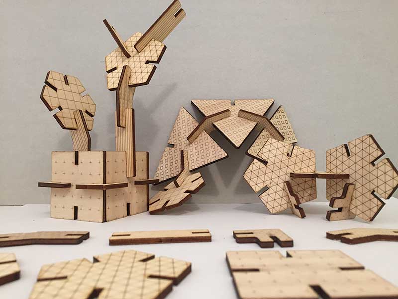
Design, lasercut, and document a parametric press-fit construction kit
To realize this exercise I decided to model the two parametric pieces with Fusion 360. I considered 0.1 mm of kerf when I exported my 3D model from Fusion 360 with the plugin DXF for Laser.
I cutted everything with a Spirit GLS machine and using the print driver from Rhinoceros, (I also did the nesting on rhinoceros).

Part 1
 I started modeling the joint in order to constrain and parameterize the parts of the piece based on the thickness.
 I later built this figure with the circular pattern command. I then made the end points of the sides coincident.


Designed in this way I was able to draw pieces of 3, 4, 5, 6 and even 12 faces without losing the functionality of the joint. I then chose to leave the user free to cut pieces of two sizes (large or small), for my example I cut the small ones.
Part 2

Also for this piece I started setting the joint and putting the other dimensions according to the thickness of the material.

In the following screenshot you will find all the parameters I used to make the two pieces parametric.
 After this work I exported the six pieces chosen with the help of the Fusion 360 DXF FOR LASER plugin.

This plug in allows you to save the dxf which I then opened in Rhinoceros for nesting. I made some fittings before putting the piece on the table. I chose to cut on a 4 mm thick plywood. I set the kerf: 0,1 mm.
You can download the model here.

Setting lasercut files and machine
Before nesting I added vector fills in Rhinoceros to make a pattern on the different pieces. This is useful to make them more recognizable for children. I put in a level the screens for the engraving, in the second the cutting lines and in the third the rectangle of the tablet. I assigned these cutting parameters to the laser:

I am very satisfied because the joints work perfectly: they are solid but not permanent.


During the nesting I also made some semi-circles useful for extracting the pieces, these can serve as a basis for the packaging.

Rhinoceros VS Fusion 360
Try "fusion 360" has led me to make different considerations than modeling with Rhinoceros.
For lasercut:
The Fusion 360 DXF for Laser plugin makes Fusion very convenient to avoid having to calculate tolerances on all parts: this greatly reduces the margin of error. Rhinoceros is very convenient for nesting, but above all because in Opendot it is directly connected to the machine. Since in this step we work with the 2D part of the software, there are alternatives to Rhinoceros. Many work with Illustrator or Inkscape to make the final step for CAM file.