- Final Project
Brainbox
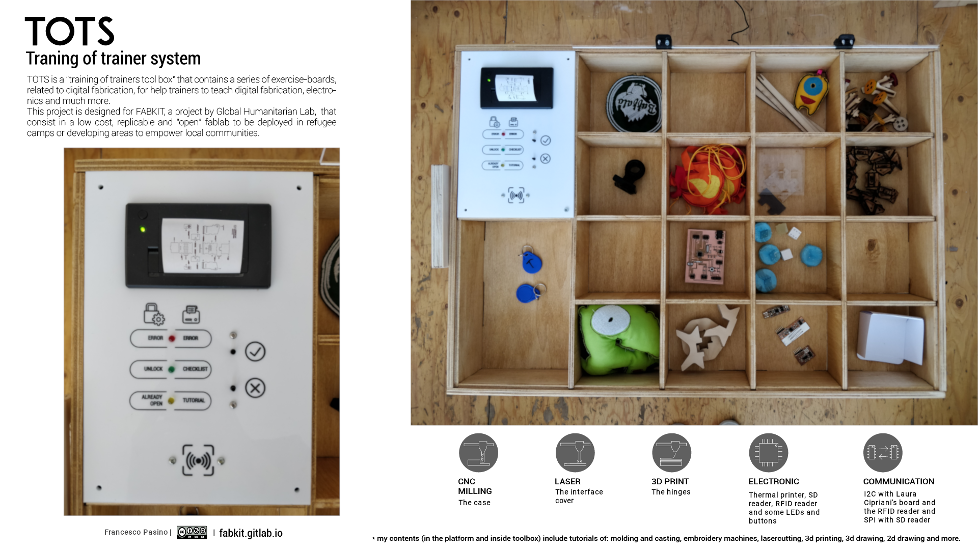
Brainbox is an ambitious project that aims, inside FABKIT, to be an educational tool useful in contexts in contact with refugees. A wide range of digital manufacturing technologies are used for its realization, so as to learn the basics of it by constructing one.
It is a removable top part of Laura's final project. It is always designed for FABKIT, a project by Global Humanitarian Lab.
Intro
Brainbox is more than a simple container, it provides a series of tutorials with which to have a first contact with digital manufacturing technologies. There are also sample objects that show the final result. The two have in common a series of RFID linked to them that allow the printing of specific information, such as, for example, vademecum and checklist.
Presentation
Brainbox consists of 16 compartments each containing a "fabbed" object along with an RFID tag and a panel containing the interface. Passing the RFID tag over the reader on the interface, after confirming by pressing the button at the top, a checklist and/or tutorial on the "fabbed" object will be printed.
Make it!
BOM
To realize the structure are necessary:
- wood panel 15mm 1270x284mm
- wood panel 8mm 1172x726mm
- transparent plexiglass panel 4mm 550x514mm
- white (or a colour of your choice) plexiglass panel 4mm 550x514mm
- 4 M4x20 screws with nuts
- 4 M3x16 countersunk head screws with nuts
- 2 M3x25 screws
- 4 6x15mm screws for wood
- a bit of filament for 3D printing (PLA, ABS, PETG or etc.)
To realize the controller board are necessary:
| Quantity | Component | Package | Function | Link |
|---|---|---|---|---|
| 1 | ATMEGA328P-AU | TQFP | The microcontroller | Farnell |
| 1 | Crystal oscillator 16 MHz | HC-49 | Resonator | Farnell |
| 2 | Ceramic capacitor 22pF | 1206 | Resonator | Farnell |
| 2 | Ceramic capacitor 1uF | 1206 | 5v power supply filter | FTDI reset filter | Farnell |
| 1 | Ceramic capacitor 10uF | 1206 | 5v power supply filter | Farnell |
| 1 | Ceramic capacitor 0.1uF | 1206 | 5v power supply filter | Farnell |
| 2 | Ceramic capacitor 4.7uF | 1206 | 9v power supply | Farnell |
| 1 | Linear voltage regulator 7805 | SOT-223 | 9v power supply | Farnell |
| 1 | Power Jack SMD | Package | 9v power supply | Farnell |
| 1 | 6x1 Header | tht | FTDI | Farnell |
| 1 | 3x1 Header | tht | Thermal printer communication | Farnell |
| 1 | 2x2 Header | smd | Thermal printer power supply | Farnell |
| 1 | 3x2 Header | smd | ISP/SPI | Farnell |
| 1 | 4x2 Header | smd | 2x I2C | Farnell |
| 1 | 5x2 Header | smd | GPIO | Farnell |
| 2 | 4.7KΩ Resistor | 1206 | I2C pull-up | Farnell |
| 1 | 10KΩ Resistor | 1206 | Reset | Farnell |
| 1 | 220Ω Resistor | 1206 | Power LED | Farnell |
| 1 | LED | 1206 | Power LED | Farnell |
| 1 | Button | Package | Reset | Farnell |
| 1 | Switch | Package | ISP/SPI switch | Farnell |
To create the interface I soldered the two momentary buttons on a multi-hole base, while the three 5mm LEDs with soldered 220Ω resistances are glued with hot glue. In addition, I bought a thermal printer that fits into the panel and the NFC reader to screw to the panel.
Fabrication
For the making of the structure were used the pantograph milling machine to work the wooden panels, the lasercutter to work the plaxiglass and the 3D printer to make the hinges. While for the control board was used the little milling machine.
Structure
The structure consists of 16 small equal compartments covered by a transparent panel that can be opened, a free compartment and a compartment containing the control board and interface.
The main part after the milling has been assembled with vinyl glue and treated with impregnating agent in order to make it durable over time. See assignment 07 for more details.
Cover
With transparent plexiglass has been realized the cover.
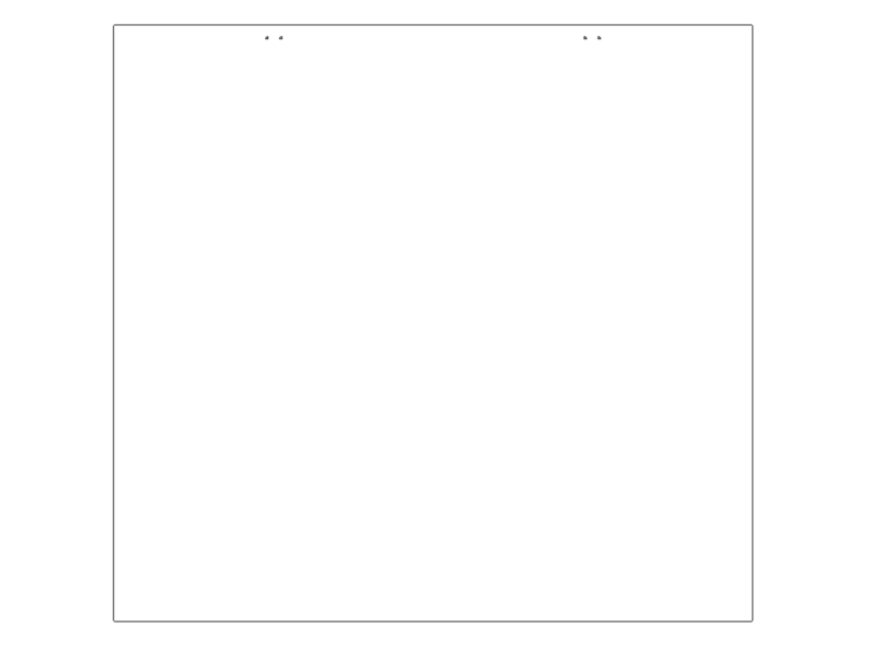
Figure 1. Cover layout.
The hinge consists of two 3D printed pieces. To assemble it I used the M3x25 screws as pivot, then I joined it to the cover with the M3x16 countersunk head screws with nuts and to the structure with the wood screws
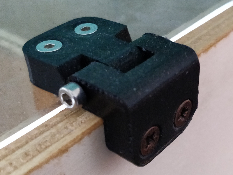
Figure 2. Hinge.
Below the compressed folder with all the files.
download structure 3,30 MB (.zip)
Interface
When an RFID tag passes on the reader a led will light up, the description is engraved on the panel on two columns, one relating to the RFID tags to open the drawer and one relating to the tags of the objects.
The interface panel is made with coloured plexiglass. The red areas are engraves that I then colored with a marker pen and cleaned the smears with alcohol to give it that bright contrast.
The LEDs and the thermal printer are snap-in, while the RFID reader and the buttons are screwed in with two M3 screws each. The panel is screwed with 4 M4x20 screws with nuts to the structure.
download Interface 1,01 MB (.dxf)
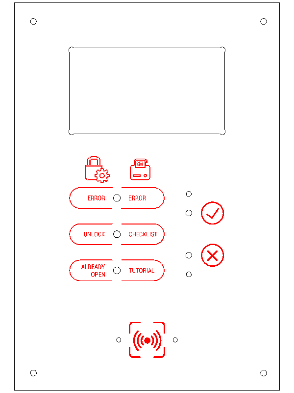
Figure 3. Interface layout.
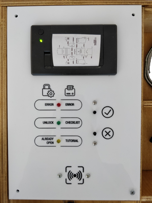
Figure 4. Interface photo.
Board
The board is the same of Output Devices week with the thermal printer and
the NFC reader.
In addition I have connected a SD card reader with SPI connector, Laura's board via I2C and 2 buttons and 3
LEDs in the following way:
#define LED_R_PIN 5 // pin for the RED LED
#define LED_G_PIN 6 // pin for the GREEN LED
#define LED_Y_PIN 7 // pin for the YELLOW LED
#define BTN_Y_PIN 8 // pin for the YES BUTTON
#define BTN_N_PIN 9 // pin for the NO BUTTON
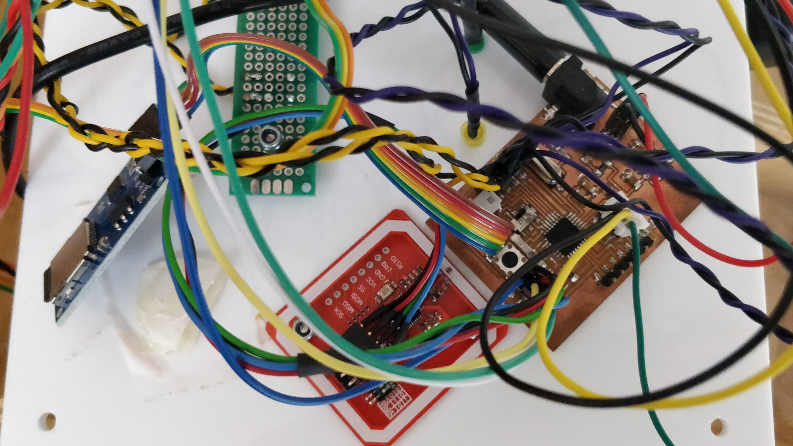
Figure 5. Connections.
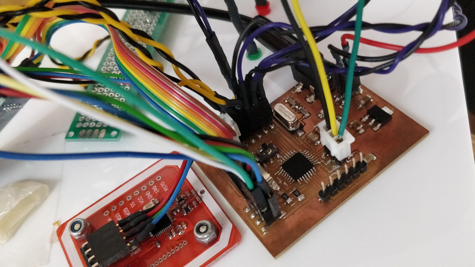
Figure 6. Connections.
Sketch
The sketch I wrote resumes the one of the output week, but identifies two tags, one that sends a signal via I2C to Laura's board to open the drawer unit below and one that prints with the thermal printer a vademecum of example. This is currently saved in memory as an image; for the conversion I used a small program written with Processing that at startup opens an image file of your choice and exports a .h file that can be imported into Arduino IDE like it's a library by placing it in the same folder as the sketch.
In the future I expect to have at least one checklist and/or a vademecum for each object with an attached qr code that leads to a web page containing all the detailed information, for example.
download Sketch 9,15 KB (.zip)
Development
What is the deadline?
The deadline to finish the FabAcademy is January 30, to finish the other objectives there is not yet a time limit.
What tasks have been completed, and what tasks remain?
I have completed a demo of the working, that is when you pass a tag or you open the Laura's drawer or you print a sample of a vademecum. Before we can make Brainbox really usable we need to expand the content, at least one for digital manufacturing technology.
The main problem at the moment is the updating of the content, it is currently very difficult and limited. To
simplify the process, the next step is to save them on the SD card instead of the internal memory of the
microcontroller.
Ideally, the file to be saved on the SD card would be downloaded from the web page of the tutorial. Before
proceeding, however, it is necessary to find a format that is easy to read and interpret and versatile for
printing with the thermal printer.
How will I complete the remaining tasks in time?
To complete the part of printing from SD card I must devote several more hours of programming, trying different approaches.
What has worked?
The demo made works correctly and both the thermal printing and the opening of Laura's drawer proceed well.
What hasn't?
I was not able to print directly from the SD card as the data needed by the Adafruit library used does not have the same format.
What questions still need to be resolved?
Another important step to improve the usability of the project is the dynamic generation of the file from the content of the web page of reference, ie it is not necessary to manually update the file with each change of the tutorial, but is generated immediately before downloading, a bit 'like the Firefox Reader View.
For example, if you wanted a checklist from this tutorial that I wrote, you could generate it from the TOC and it would become something like that:
3D model with Onshape
 [ ] Intro
 [ ] Base
 [ ] Letter
 [ ] Handle
 [ ] Hole
 [ ] Fillet
 [ ] Export
This should help during the next realizations (surely on procedures to use the machines a checklist would be more suitable).
What have you learned?
During the FabAcademy I learned the basics of HTML and I was able to test some concepts in practice that I already had the theoretical basis, such as the milling cutter, molding and casting. I already had good knowledge of other prototyping technologies.