- Assignment 07
Computer-Controlled Machining
During this week I realized the structure of my final project using the ShopBot.
CAD
With Solidworks I designed the structure, while with Rhinoceros I made the layout.
Design
The external external dimensions are 716x504x80mm and it is
designed to be made with 15mm thick panels for the side
walls and 8mm for the bottom and the internal walls.
All the joints are designed so that they cannot be seen once the
box is assembled, this allows to avoid the excessive accumulation
of dust and to trap small objects if there were any.
download structure 3,02 MB (.zip)
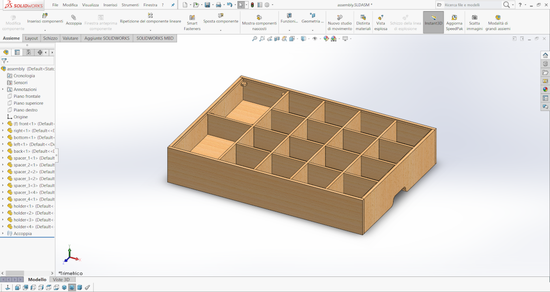
Figure 1. Screenshot of Solidworks.
Layout
For the table I exported the relevant face of each piece to DXF and nested it. In blue are represented the lines with the depth of cuts of 8mm and in red those of 15mm, while the green areas are the pockets of 5mm.
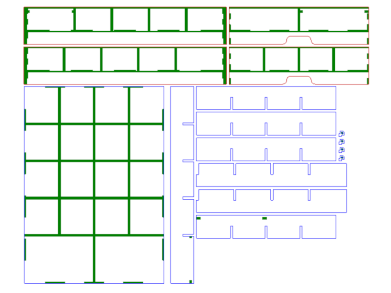
Figure 2. Layout.
With this arrangement the required area of the 15mm wood panel is 1270x284mm and the area of the 8mm wood panel is 1172x726mm.
CAM
The program I used is VCarvePro by Vectric, ideal for 2D and 2.5D toolpaths.
Figure 3. VCarvePro by Vectric.
Before I make the toolpath of the 15mm wood panel, but the process
is the same for the 8mm too.
The first step
after importing the DXF is to select the starting point and the
material thickness.
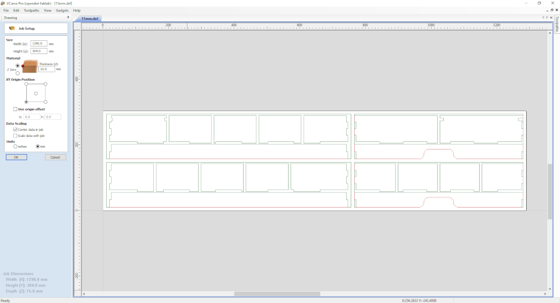
Figure 4. Starting from surface.
Then I manually inserted the 'T-Bone' Fillet so that they can not be seen in the assembled structure.
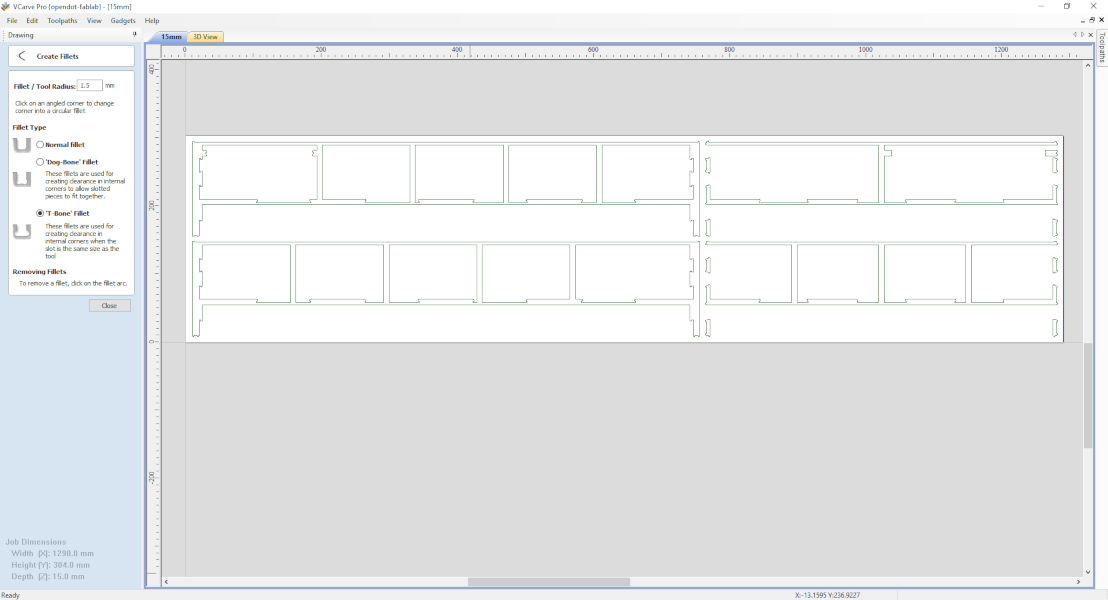
Figure 5. 'T-Bone' Fillet with 1,5mm tool radius.
Now it's time to add works. The first one to be executed is the Pocket, then I selected all green borders and set a depth of 5.5mm (5mm+0.5mm tolerance). As a tool I have selected a 3mm End Mill.
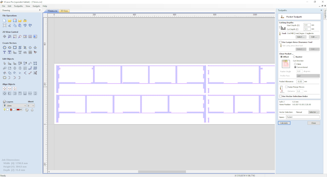
Figure 6. Pocket Toolpath.
I created the external path, here, in addition to selecting the Cutting Depths (15.5mm) and the Tool (the same as before), I set the external profile and added manually the Tabs so that the workpiece does not detach during machining.
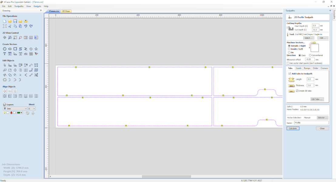
Figure 7. 2D Profile Toolpath.
From the tab 3D View you can see the 3D rendering of the finished part to check if there are any errors.
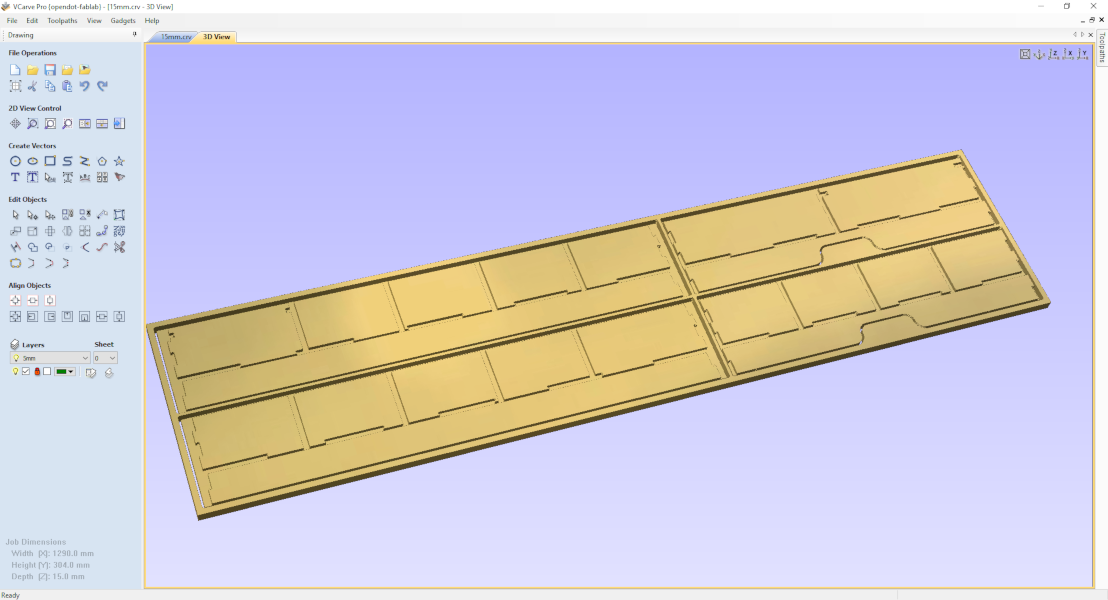
Figure 8. 3D View.
You can also view the toolpath to verify that there are no collisions clicking on Preview All Toolpath.
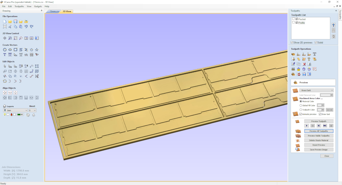
Figure 9. Start the simulation.
The last step is to export the toolpath in the format for the ShopBot, which is sbp.
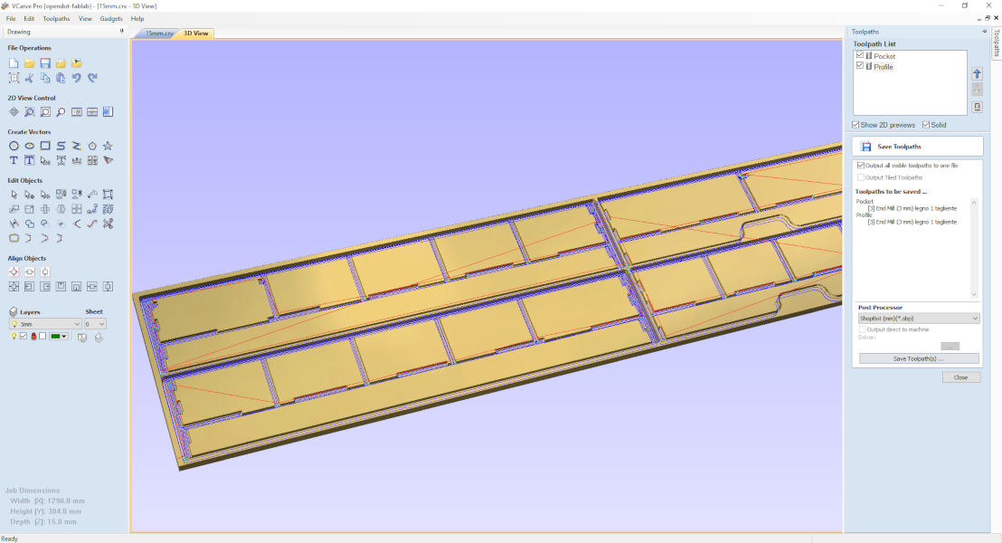
Figure 10. Post Processor
In addition to the toolpaths (both 15mm and 8mm) I also saved the native files of the program (crv) so I can easily make changes without repeating everything again.
Milling
The milling procedure is the same for both the 15mm and the 8mm.
Preparation
First, I fixed the wood panel to the worktable with screws. Then, after checking that the cutting edge of the tool was long enough, I mounted it on the spindle.
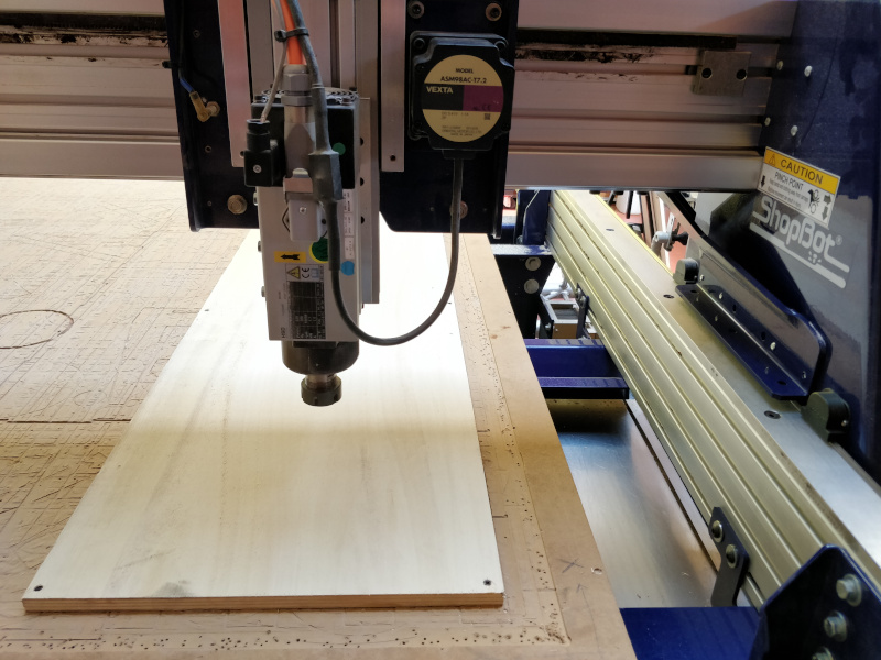
Figure 11. Wood panel fixed with screws.
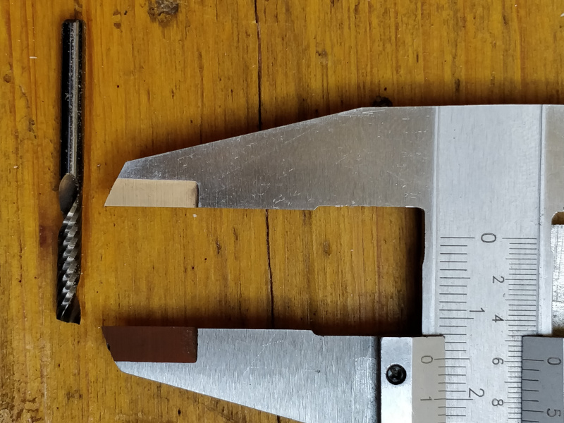
Figure 12. The cutting edge is more then 15mm.
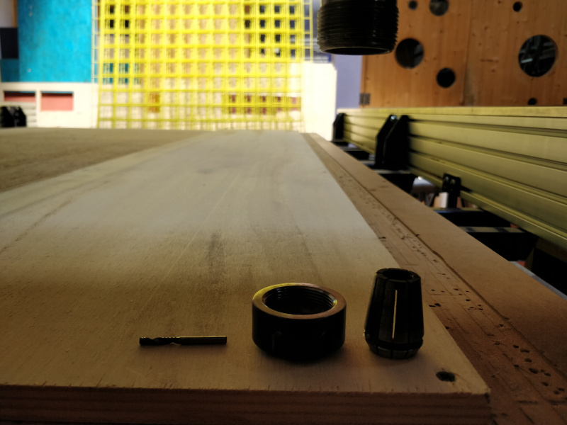
Figure 13. the three components to be assembled.
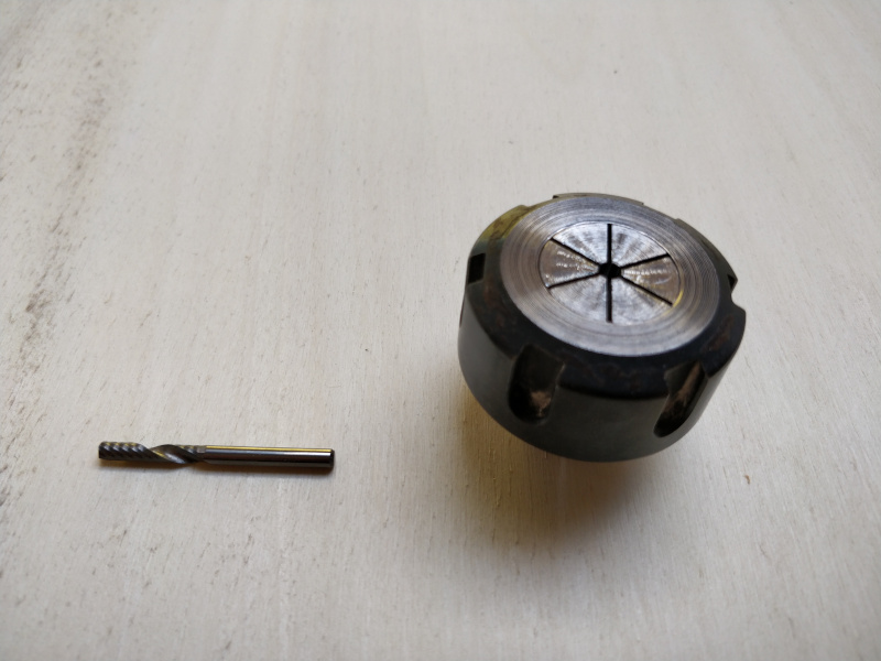
Figure 14. First the two pieces of the spindle .
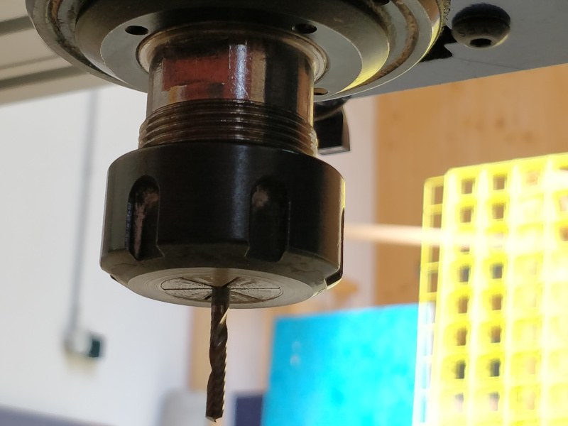
Figure 15. Then screwed to the fillet and insert the tool.
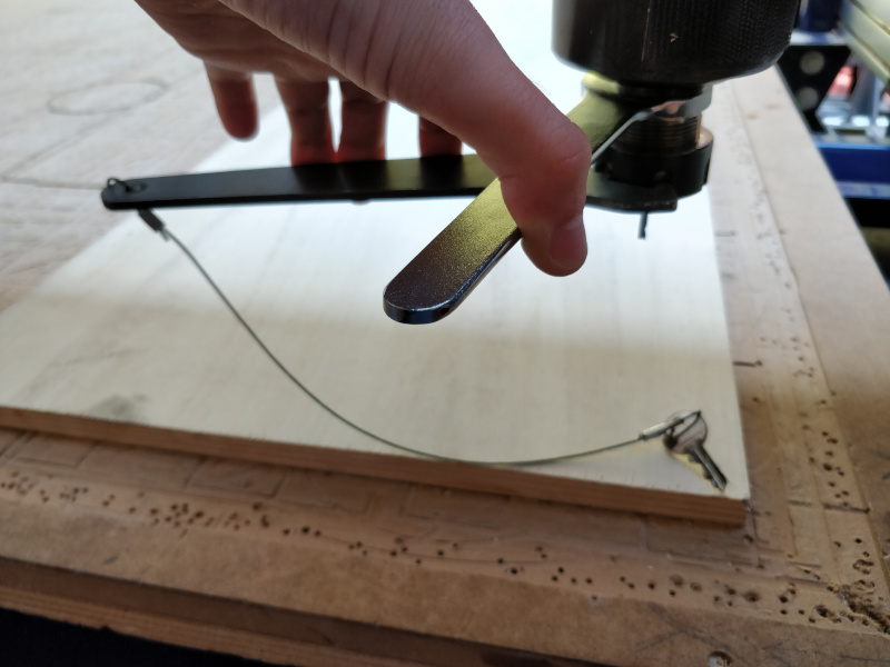
Figure 16. I hold it well.
Finally, I can turn on the machine. Note that the key in Figure 17 is the same as in Figure 16.
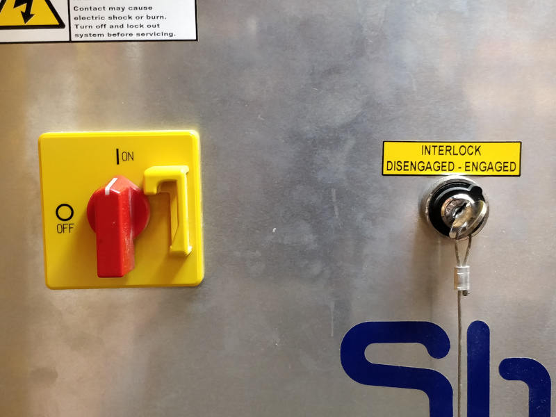
Figure 17. I'll turn on the machine and off the safety.
Starting the work
The next step is to find the zeroes of the axes, starting with Z using the appropriate machine tool and the automatic feature of the host software.
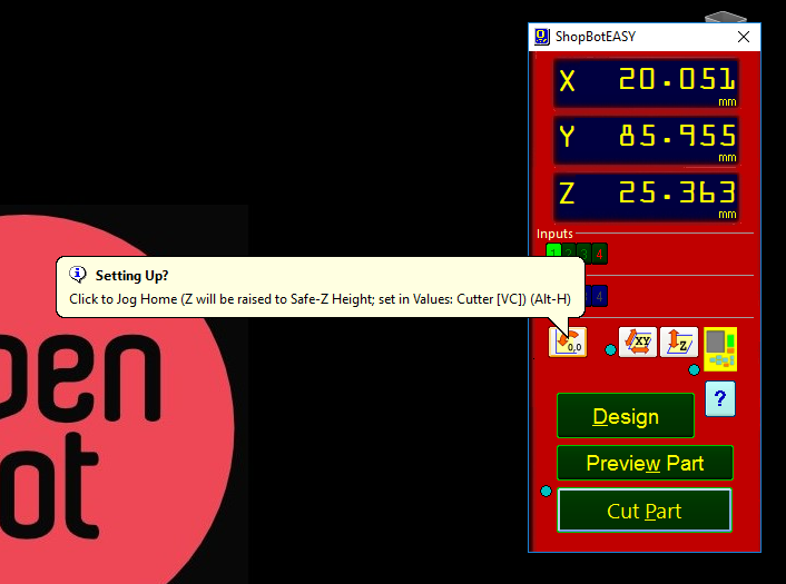
Figure 18. The button is where the cloud comes from.
Clicking on the button that represents the keypad it opens
and from here I moved the spindle in the lower left corner (as
selected in the CAM).
To set the zero of X and Y I pressed on
Zero Axes. Now they are at 0.000.
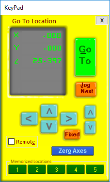
Figure 19. KeyPad
Clicking instead on Cut Part the window opens to select the file and, after doing this, I pressed on START.
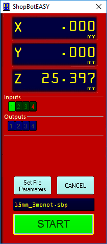
Figure 20. Cut Part window.
An alert window opens to warn you that the spindle will start. Clicking on OK will start the work.
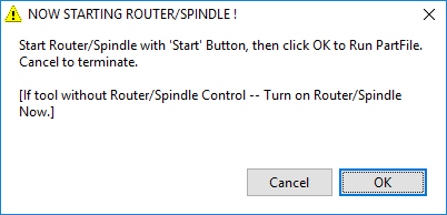
Figure 21. Alert
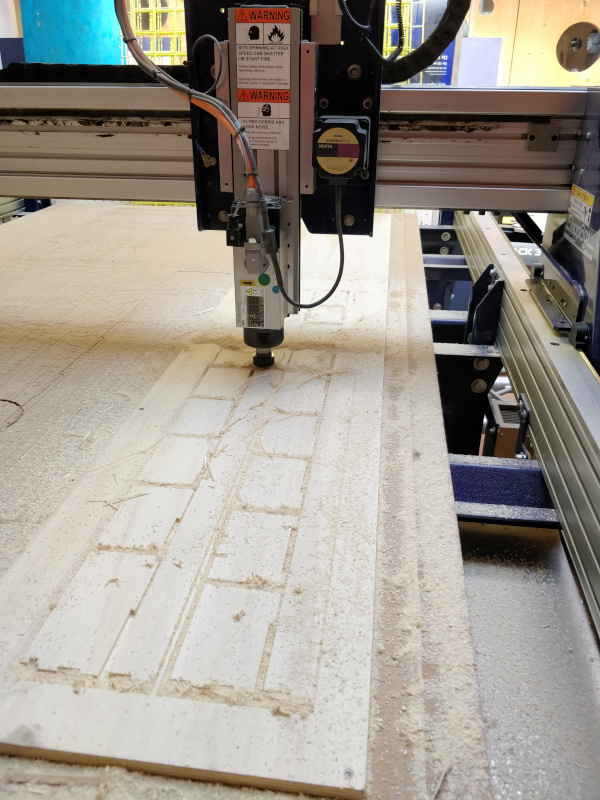
Figure 22.
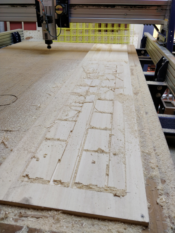
Figure 23.
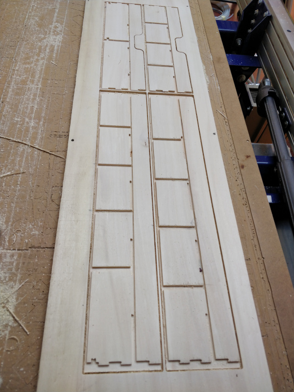
Figure 24.
Assembly
For the assembly I first mounted the internal crossbars, then the outer sides with the bottom, finally I joined the parts with vinyl glue and applied a coat of impregnated to protect the wood.
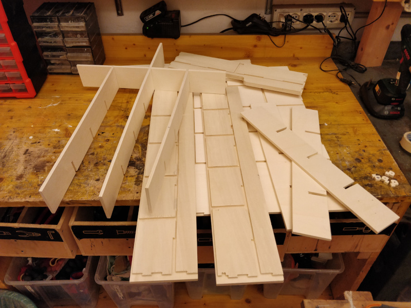
Figure 25. Internal crossbars
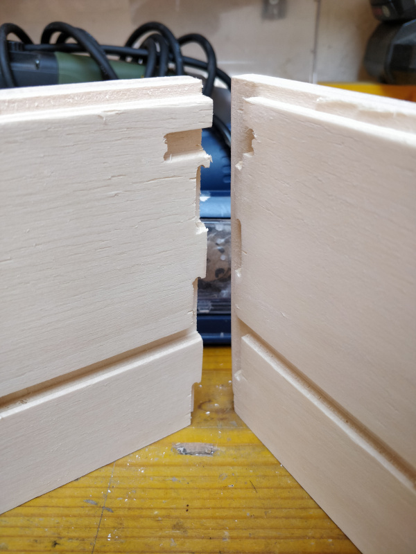
Figure 26.
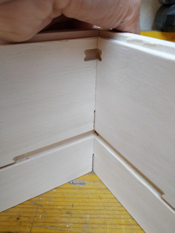
Figure 27.
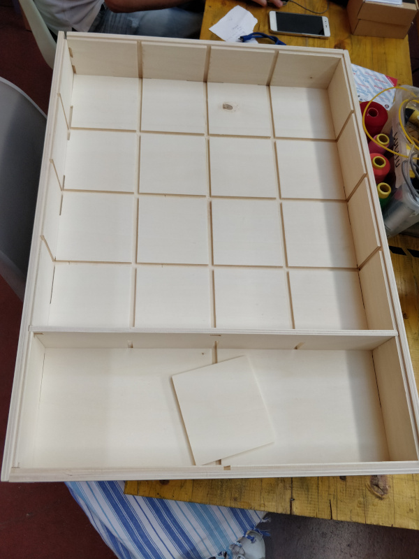
Figure 28.
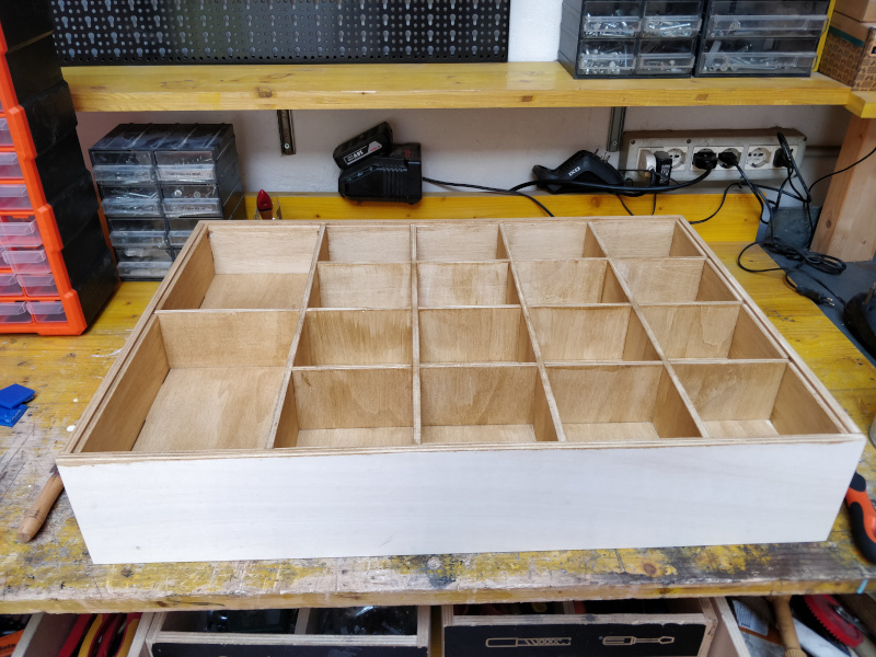
Figure 29. After impregnating.
Group Assignment
More info on the Opendot group assignment page.