- Assignment 11
Output Devices
I chose the thermal printer from among the various outputs that will be useful for the final project, so I designed a pcb that I could use for it too.
Thermal printer
Hardware
To control devices I have chosen the ATmega328-AU microcontroller powered by a 9v power supply via a voltage regulator to reduce the voltage to 5v.
Design
The thermal printer is controlled with SoftwareSerial and consumes about 1.5A, so I put two different connectors: a 2x2 where the 9v power supply with two GND and two 9v to be able to withstand the amperage and a 1x3 to plug the printer GND, TX and RX.
To these I added another set of connectors linked to 5 GPIO, to the I2C and a switch that disconnects the Reset pin to the ISP connector and connects the SS pin to use it with the SPI protocol.
I designed the board with EAGLE and milled it with Roland MDX40. These are the result and the pinout.
download FinalProjectBoard 118 KB (.zip)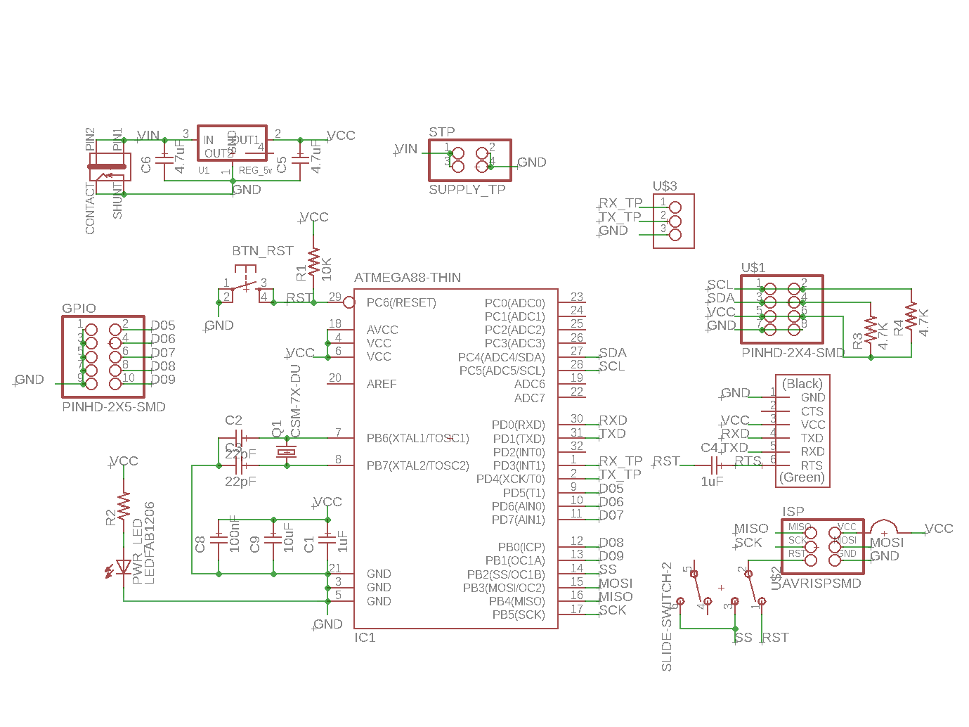
Figure 1. The schematic in EAGLE
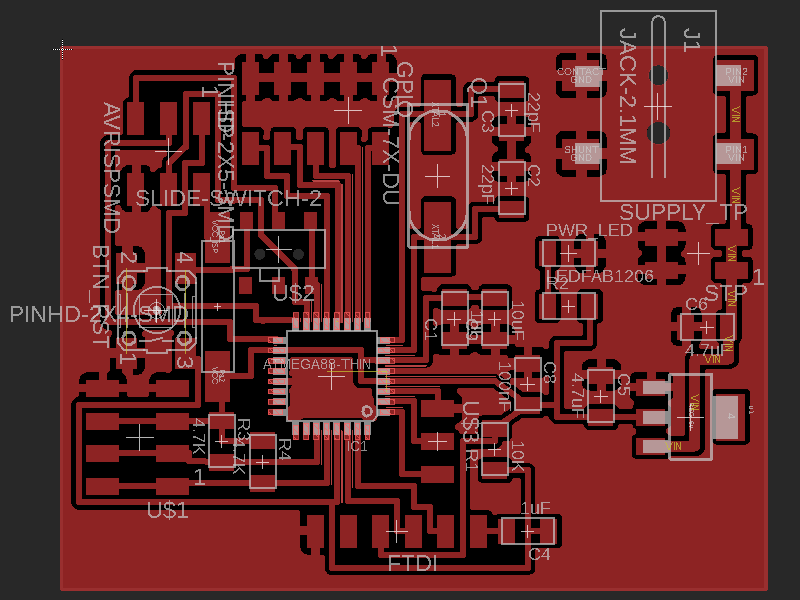
Figure 2. The board in EAGLE
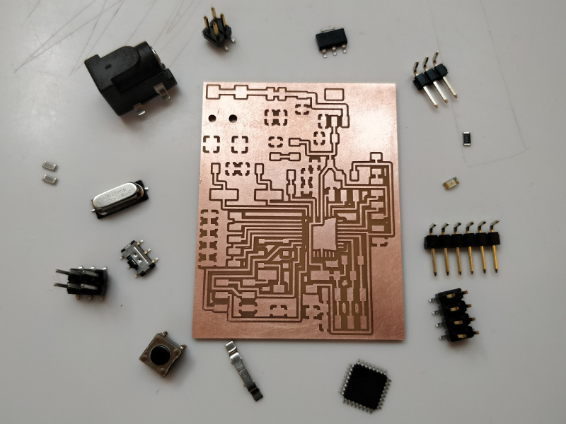
Figure 3. The board with component
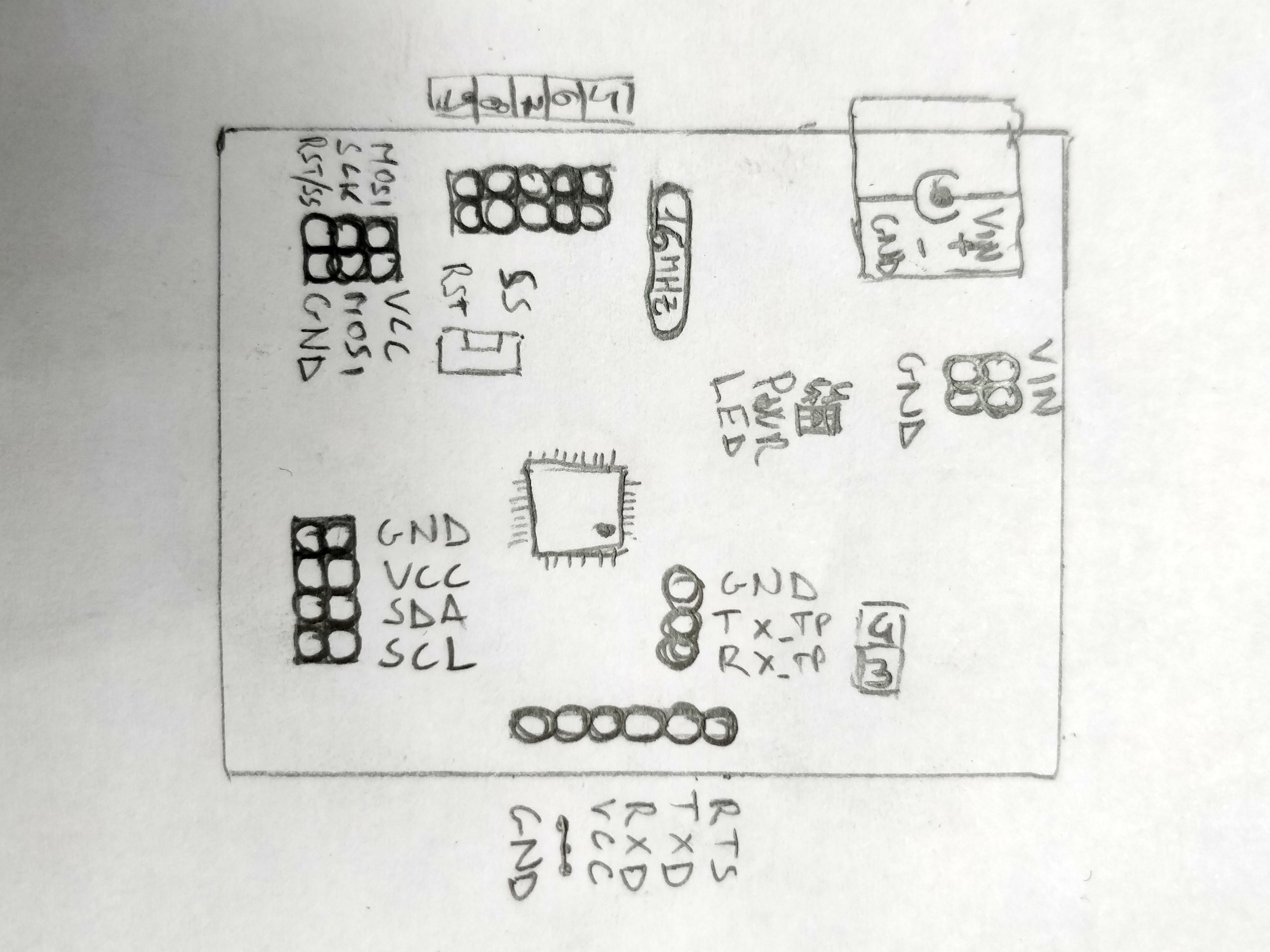
Figure 4. Pinout
Assembly
The assembly of this board was more difficult than the previous boards both because of the greater number of components and because of the pitch of the microcontroller is 0.8 mm compared to 1.27 mm of the ATtiny.
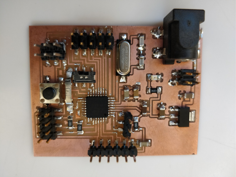
Figure 5. The board assembled
Separately I also soldered a female connector to power the thermal printer.
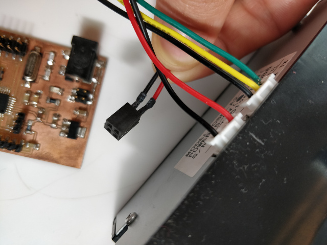
Figure 6. The power connector for thermal printer
Software
To write the sketch to load on the microcontroller I used Arduino IDE and its Serial Monitor to send the texts to be printed.
Requirements
To use the printer you need a library, I found one easy to use on Adafruit so I added the https://adafruit.github.io/arduino-board-index/package_adafruit_index.json
repository to the preferences and in the Library Manager I installed the Adafruit Thermal Printer
Library.
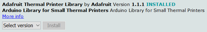
Figure 7. Adafruit Thermal Printer Library
Since no board of Arduino is equipped with this chip (but only the ATmega328P) I also had to install the
core, I found one very good with a lot of documentation about it on a Github page and this is the link
https://mcudude.github.io/MiniCore/package_MCUdude_MiniCore_index.json to add in preferences.
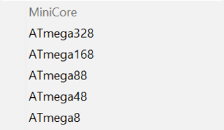
Figure 8. MiniCore in Tools
Sketch
The sketch reads the characters that are sent by the serial monitor and immediately sends them to the thermal printer, during the print a led on pin 9 turn on to check if the board works correctly in case the printer has a problem.
download ThermalPrinterBySerial 965 byte (.zip)Result
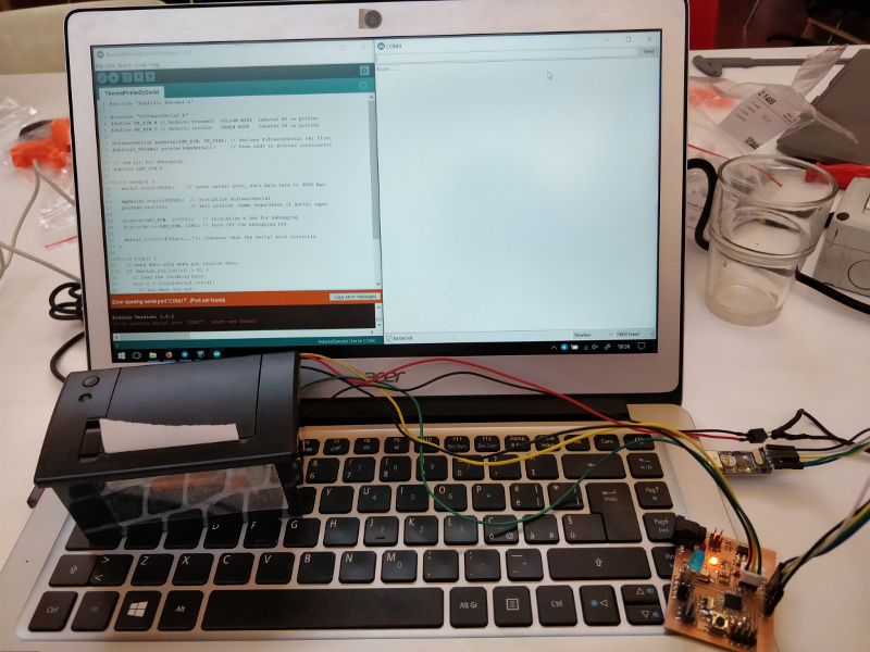
Figure 9. On turn on it print Start...
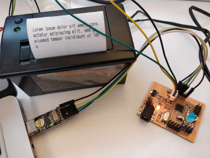
Figure 10. The print!
Stepper motor
Because the thermal printer is not a normal output, during Machine Design week I was responsible for controlling the bipolar stepper motors using external drivers.
Hardware
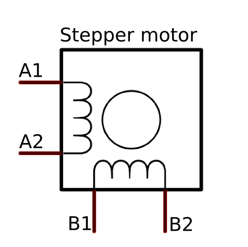
Figure 11. Bipolar stepper motor
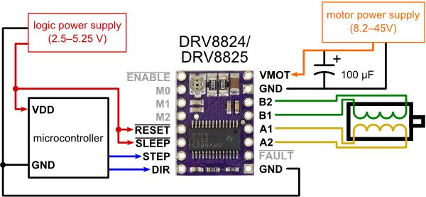
Figure 12. DRV8825
Two output pins are used for control: STEP and DIR.
Each time the STEP pin changes from LOW to HIGH and again to LOW with a minimum delay of 1.9µS
(datasheet sec. 7.6) a step is done.
To know how many steps are needed to complete a revolution is enough to multiply 360 per the microstepping
set on the driver and divide by the step angle, in my case:
` steps__per__revolution = (360 * 32) / 1.8 = 6400 `
To set the microstepping to `1/32` I connected the pins M0, M1 and M2 to Vcc
as explained in the
vendor product page.
Instead the DIR pin is used to set the direction of rotation, set to HIGH will rotate in one direction,
otherwise in the other.
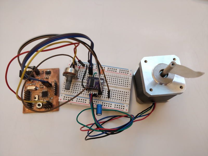
Figure 12. DRV8825
Software
To test the motor I wrote a sketch that performs a clockwise and an anticlockwise rotation and so on. Also
with a potentiometer I can adjust the speed of the rotation.
Note that digitalWrite() takes more than 1.9µS to process.
#define STEP_PIN 3
#define DIR_PIN 4
#define D_PIN A5

uint8_t d = 0; // delay
bool dir = false; // direction

void setup() {
  // pin setup
  pinMode(STEP_PIN, OUTPUT);
  pinMode(DIR_PIN, OUTPUT);
  digitalWrite(STEP_PIN, LOW);
}

void loop() {
  // read potentiometer to set the delay
  d = map(analogRead(D_PIN), 0, 1023, 1, 20);
  // change direction
  dir = !dir;
  digitalWrite(DIR_PIN, dir);
  // It do a revolution
  for (int i = 0; i < 6400; i++) {
    digitalWrite(STEP_PIN, HIGH);
    digitalWrite(STEP_PIN, LOW);
    delay(d);
  }
}
Result
Group Assignment
More info on the Opendot group assignment page.