- Assignment 15
Machine Design
In this week in which it was necessary to conclude the basket-robot I designed the electronics and configured the firmware with the help of Gianluca. I leave Alberto the part of the interface that controls the robot via GCODE.
Elettronic
The electronics required to control the robot are four NEMA 17 stepper motors connected in pairs but with opposite polarity, an IR sensor, a blue LED and a Bluetooth module.
Board
To control all the electronics I designed a board with EAGLE being careful that it was compatible with the firmware I chose to use: GRBL v1.1. This CNC firmware allows easy stepper control via GCODE.
Requirements
I used EAGLE to draw the board. I found in the Reprap.org wiki a library with all the fingerprints necessary to insert the drivers so I downloaded it and added it to the project. Unfortunately I noticed that some pins didn't match so I had to modify them.
Design
For the driver control scheme I was inspired by RAMPS 1.4.
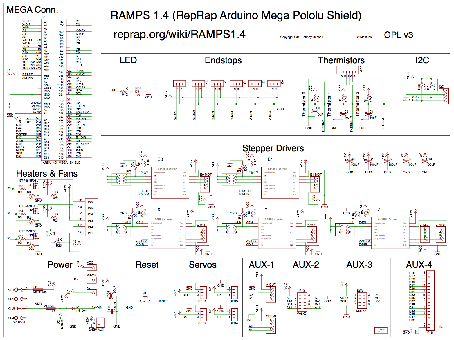
Figure 1. Driver schematic on RAMPS 1.4
Because when I designed the board I still didn't know exactly what to use I put two connectors, one with the endstops and one with the spindle controls. For Bluetooth I used the FTDI connector.
download RoboTable 208 KB (.zip)
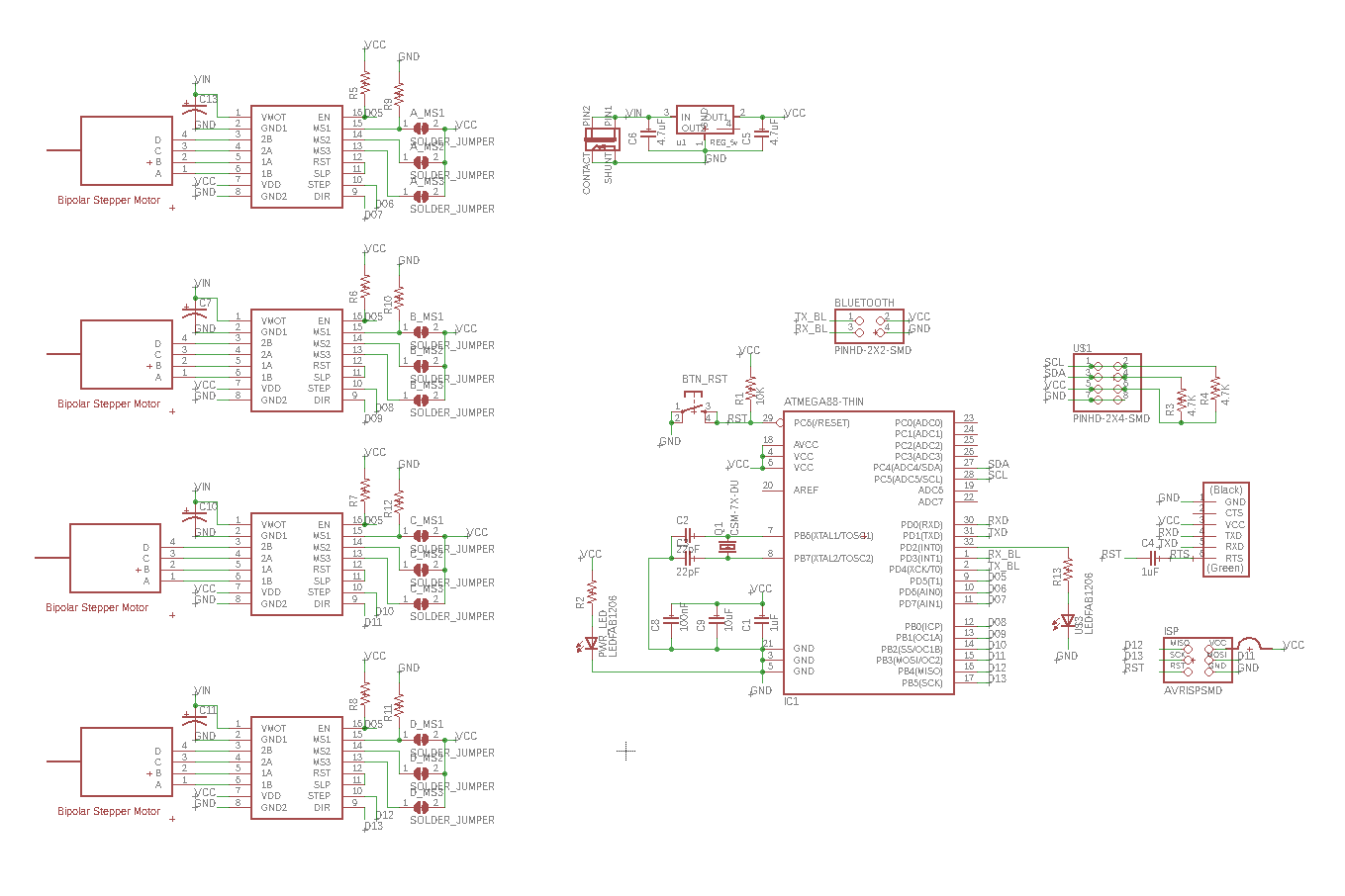
Figure 2. Schematic
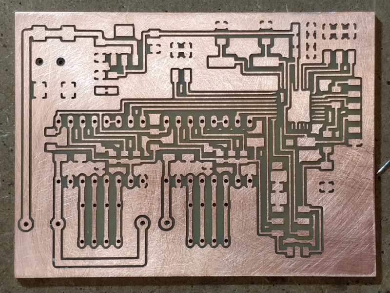
Figure 3. PCB
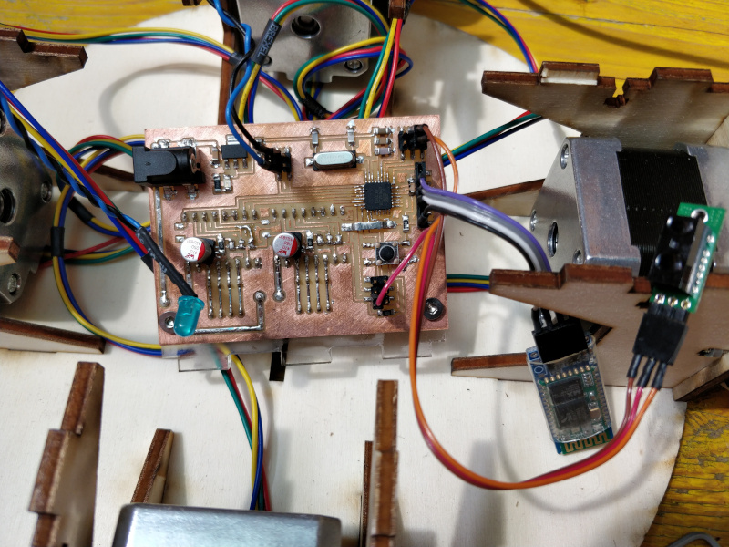
Figure 4. Board
Drivers
To control the steppers I used external drivers connected to the board: the DRV8825. To limit the current supplied and avoid damaging the motors and/or the drivers themselves, they need to be adjusted by turning the small trimmer on the circuit. To know the current that will be delivered you have to measure with the tester the voltage between the GND and the head of the trimmer (Vref) and do the calculation as reported in the official documentation: ` I = Vref*2 ` .
However, since two motors are connected in parallel to each driver (with opposite polarity), the current that will go to each motor will be half of that supplied in total, that is : ` I = Vref ` .
I set them to 1v to avoid that the drivers, delivering too many amps, get damaged, but
the motors hold up to
1.7A so they can not provide the full torque.
All this I did after mounting the drivers on the board and having powered it otherwise
no value will be
read.
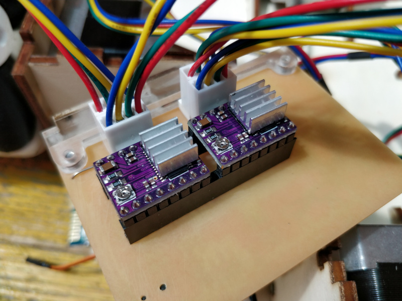
Figure 5. Drivers
IR sensor
The sensor is used to detect the presence of the ball in the basket. It has three pins GND, VCC and SENS. I soldered an adapter cable to connect GND and SENS to an endstop (it is indifferent which one) and the vcc to the ISP connector.
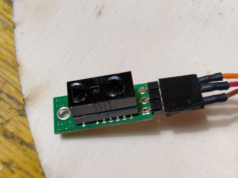
Figure 6. IR sensor front.
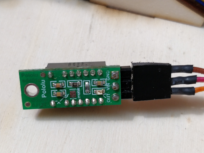
Figure 7. IR sensor back.
led
The led does not have a particular function and I connected it to the DIR pin of the spindle to be able to control it via gcode.
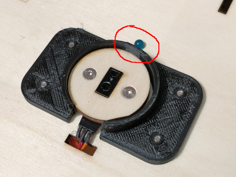
Figure 8. Led in the red circle.
Bluetooth
Since I used the FTDI connector for Bluetooth, it was only necessary to solder a cable to be an adapter.
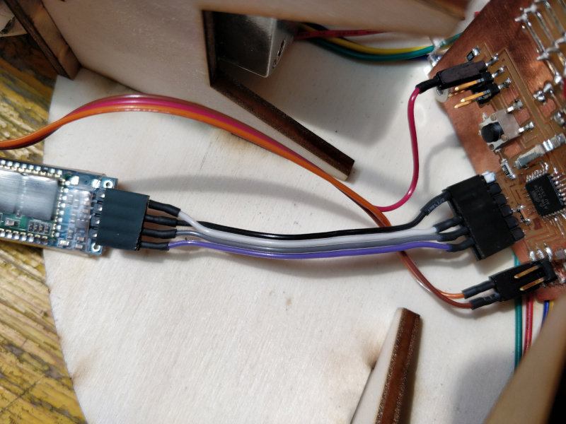
Figure 9. Bluetooth
Firmware
As already said before, the firmware I used is GRBL v1.1.
Edits
In order to use it, I had to make some changes.
In config.h:
- line 42 : change BAUD_RATE to 9600
- line 88 : disable HOMING_INIT_LOCK
- line 164: disable MESSAGE_PROBE_COORDINATES
- line 230: disable CHECK_LIMITS_AT_INIT
- line 304: disable ADAPTIVE_MULTI_AXIS_STEP_SMOOTHING
In cpu_map.h I completely remapped the pins, now the ones connected are:
- X step: 8
- X dir: 9
- Y step: 10
- Y dir: 11
- stepper disable: 7
- X limit: 2
- Y limit: 3
- Z limit: 4
- spindle enable: 5
- spindle dir: 6
In default.h I set DEFAULT_a_STEP_PER_MM to 28 and increased DEFAULT_a_MAX_RATE, DEFAULT_a_ACCELERATION and DEFAULT_a_MAX_TRAVEL for each axes going to tries.
Lastly in protocol.c I have replaced line 74 with:
bool s = false;
for (;;) {
  if (limits_get_state() && s) {
    printPgmString(PSTR("\r\n0\r\n"));
    s = false;
  }
  else if (!limits_get_state() && !s){
    printPgmString(PSTR("\r\n1\r\n"));
    s = true;
}
This allows you to receive a feedback by IR sensor via Serial.
Interface
Once switched on the robot will be in the position X0 Y0, by sending the command G1
X[posX] Y[posY] F[speed] you can tell it to move up to the
coordinates indicated.
He will normally use absolute coordinates, but it is also possible to switch to the
relative coordinates with the G91 command (G90 to return to the absolute
coordinates).
To control the led's turning on, instead, you have to use the commands M4 (turn on) and
M5 (turn off) that normally are used to control the direction of rotation of the
spindle. The feedback that is received by the sensor is a 0 when the ball enters the
basket and a 1 when it exits.
Group Assignment
More info on the Opendot machine design page.