
|
| Sukkur IBA University Merit, Quality, Excellence |
WEEK-3
Computer-Aided Design
Lecture & Recitaton of a Week:
Lecture on 31st of January, 2018: Computer-Aided Design by Neil Gershenfeld
Recitation on 5th of February, 2018: How to make (almost) anything usable by Jan Borchers
Tasks for a Week
- Model (raster, vector, 2D, 3D, render, animate, simulate, ...) a possible final project, and post it on your class page
Final Project Modeling
To complete the task I made some Graphical Models of my possible Final Project using different softwares. My designs are divided in two main types of graphical modeling which are:
- 2D Graphics
- 3D Graphics
2D Graphics
- Raster Graphics
- Vector Graphics
- GIMP
- Photoshop
- Microsoft Paint
- MyPaint
- Krita
- GraphicsMagicK
- Inkscape
- CorelDRAW
- Illustrator
- Scribus
- loDraw
3D Graphics
- Non-Parametric 3D Graphic Software
- Parametric 3D Graphic Software
- Rhinoceros 3d
- ZBrush
- Blender
- SketchUp
- TinkerCAD
- 123D Design
- Make a 2D box on red and green axis using Rectangle Tool
- Made it 3D after using push/pull tool and increase its floor direction in blue axis
- After making a 3D box of my required dimensions I used offset tool to make a 5mm boundary on a top face of box
- Again using push/pull tool to the inner side of top layer and decrease it to ground till 5mm floor remains
- Make a 2D box on red and green axis using Rectangle Tool
- Made it 3D after using push/pull tool and increase its floor direction in blue axis
- After making a 3D box of my required dimensions I used offset tool to make a 5mm boundary on a front side of a box
- Again using push/pull tool to the inner side of front layer and push it toward green axis till 5mm wall remains
- After this a hollow box is made, using rectangle tool I made shapes of the wall in inner side of the cabinet.
- Again using push/pull tool to get those walls pullout, as a result shelves are made within box and this is how cabinet is done
- Fusion 360
- SolidWorks
- FreeCAD
- Creo
- ONShape
Two dimensional (2D) graphics can furthur divided in 2 types which are
Raster Graphics
A raster graphics or bitmap image is a dot matrix data structure, representing a generally rectangular grid of pixels, or points of color. Raster is technically characterized by the width and height of the image in pixels and by the number of bits per pixel (or color depth, which determines the number of colors it can represent).
Some of the most common softwares of the Raster Graphics are :
Microsoft Paint
It is hard to work in a software which has very less tools to complete the task but it is fun to work on MS Paint, it reminds me my childhood.
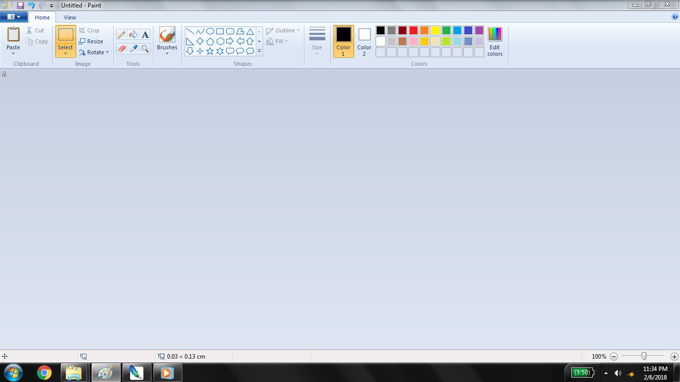
First screen after opening MS Paint
Click on resize to size the page (as needed)
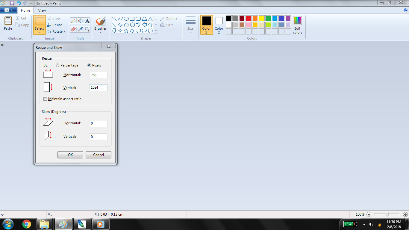
Resizing page
To make the 2D cabinet I selected Shapes> Rectangle, and draw 40 rectangles connecting ach other
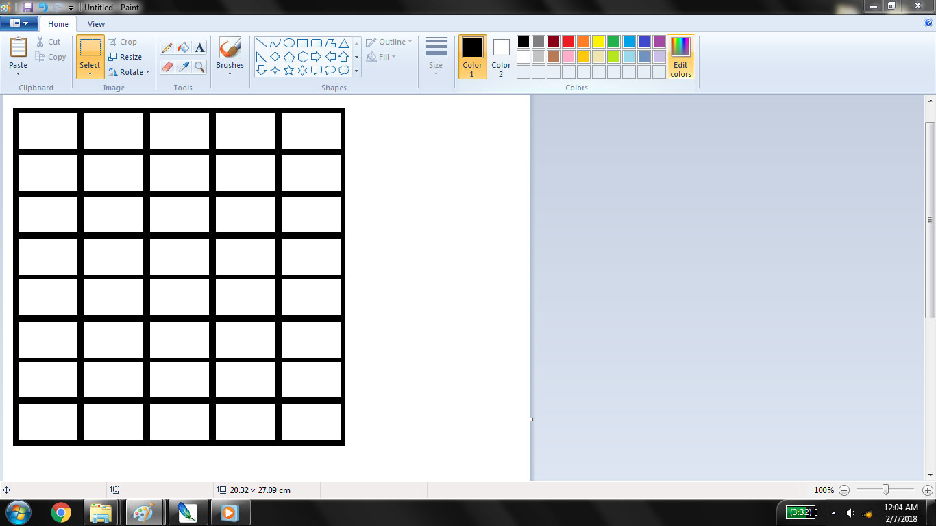
2D Cabinet Sketch
I want to glow the shelf in cabinet in which desired component is present for that I am going to apply RGB LED strip all over my cabinet for this I made that cute RGB circuit using different shapes

RGB LED circuit using different shapes
For finalizing the look I use "fill" tool to color the cabinet to look more like woods and paste my RGB LEDs all over cabinet
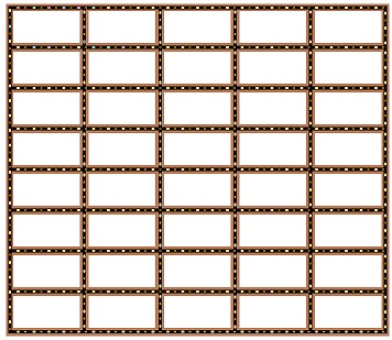
Final Look
Vector Graphics
Unlike bitmaps, vector images are not based on pixel patterns, but instead use mathematical formulas to draw lines and curves that can be combined to create an image from geometric objects such as circles and polygons. Vector images are edited by manipulating the lines and curves that make up the image using a program such as Adobe Illustrator.
Vector images have some important advantages over bitmap images. Vector images tend to be smaller than bitmap images. That’s because a bitmap image has to store color information for each individual pixel that forms the image. A vector image just has to store the mathematical formulas that make up the image, which take up less space.
Some of the most common softwares of the Vector Graphics are :
Inkscape
I selected Inkscape for vector designing because it is free and it is kind of simplest form of Adobe Illustrator. I offenly used it to make laser cutting files in SVG format.
First view of Inkscape
I decided to make a boxes for my smart cabinet. and for this I want to design the box file for laser cutting. To make perfect joints I found a tool on internet which takes size and provide the pdf file of laser cutted parts.
To make the box select Boxes> ClosedBox, give it required values and pdf is generated
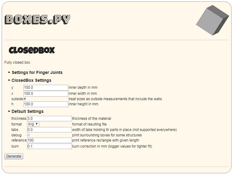
Closed Box dimension setting
The file I got from boxes.py is the closed box and I want my boxes to opened on top side thats why I opened it in Inkscape convert it in SVG (Scalable Vector Graphics) and remove the top cover and one side finger joints on all side walls
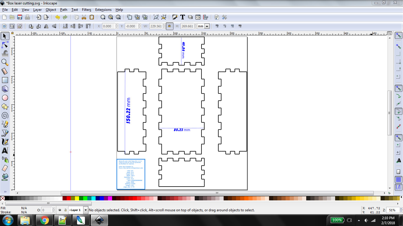
Laser Cuttable parts of box open from top
Same way I made the 40 boxes cabinet using same tool, because of big size of file there are some lacks in generated file like width of a wood is not defined etc.
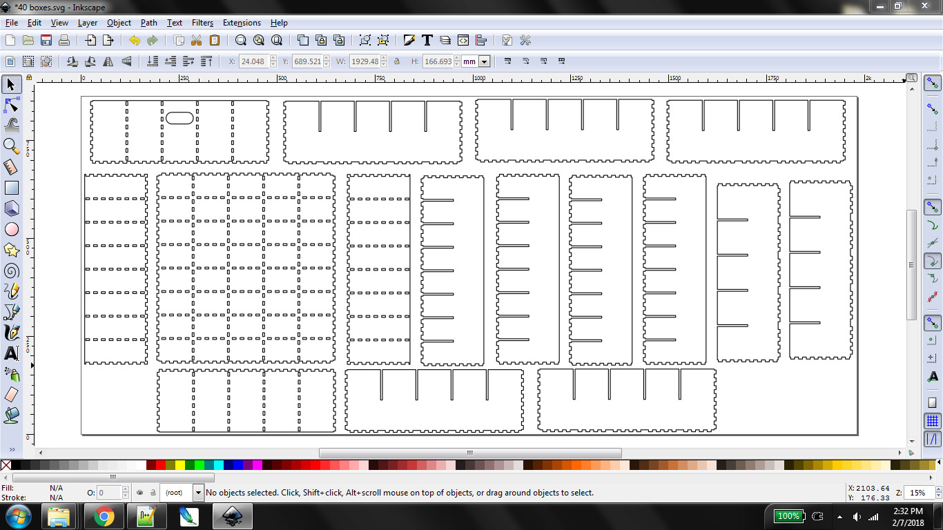
Laser Cuttable parts for 40 boxes Cabinet
To work on 3D Graphics there are two types of software available for this
Non-Parametric 3D
Non-Parametric 3D modelling softwares are those in which values are used directly instead of variables for the parameters. It is hard to change something in the model after completing it.
Some of the most common Non-Parametric 3D Softwares are :
Google Sketchup
I downloaded open source version of google sketchup named "MAKE". It has limited tools but all are enough powerfull to sketch my 3D Model. This software is very simple to use for rough modeling. For understanding the 3D modelling Environment it is better to start with this one.
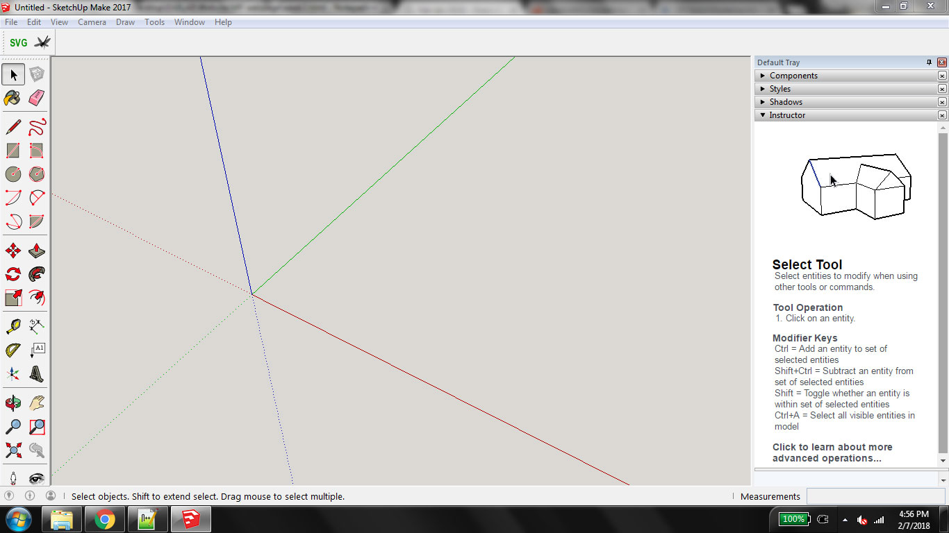
First screen of Sketchup Make
I selected "woodworking millimeters" template after opening google sketchup I want to made a 3D box for my components. Instructions for box:
3D Component Box
Instructions for making cabinet:
3D Model of a Cabinet
Parametric 3D
Parametric is a term used to describe a dimension’s ability to change the shape of model geometry as soon as the dimension value is modified. Parametric modelling uses the computer to design objects or systems that model component attributes with real world behaviour.One of the most important features of parametric modelling is that attributes that are interlinked automatically change their features. In other words, parametric modelling allows the designer to define entire classes of shapes, not just specific instances. (source http://www.designtechsys.com/articles/parametric-modelling)
Some of the most common Parametric 3D Softwares are :
SolidWorks
After understanding the 3D environment on SketchUp I moved toward my next task which is working on paramatric 3D Modeling. I selected Solidworks because many people suggest me to work on it. I felt it hard to understand when I started working on it but after some days with so many tutorials on youtube I love this software.
SolidWorks is a solid modeling computer-aided design (CAD) and computer-aided engineering (CAE) computer program that runs on Microsoft Windows.
SolidWorks 1st Screen after opening
After opening solidworks to start the project click "File" in upper toolbar then select "New", after clicking on "New" the window will pop-up to ask the kind of document there are three options,1. make a part,2. assemble/arrange the 3d parts and 3. 2D drawing. as I have to make something so I select "Part" on this window and click OK
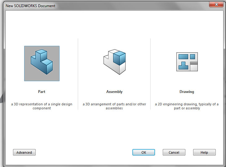
Selection of type of document in SolidWorks
I am referring a tutorial from which I used to make a box with Dovetail joints, here is the video:
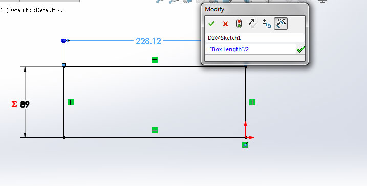
"I want to make a parametric box which is defined by its dimensions, any change occur in dimension, box shape will change with respect to that. For this I have to define some global-variables, To setting up global variables click on "Tools" then select "Equations..." as shown:
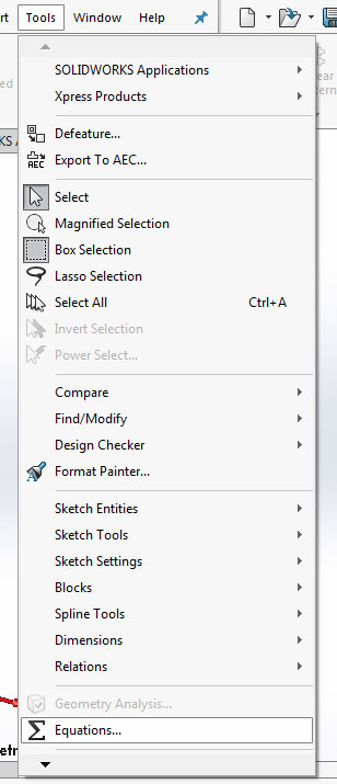
Address to change global variables
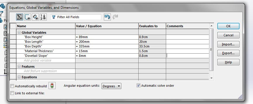
Setting up box dimensions as global variables
Now before starting sketch first we have to select the plane, I selected front plane to start
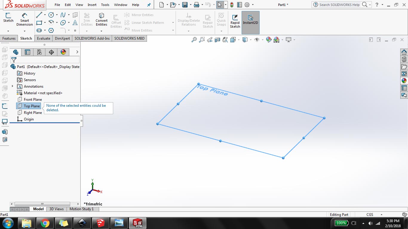
Representation of top plane
Here I share other steps of my task:
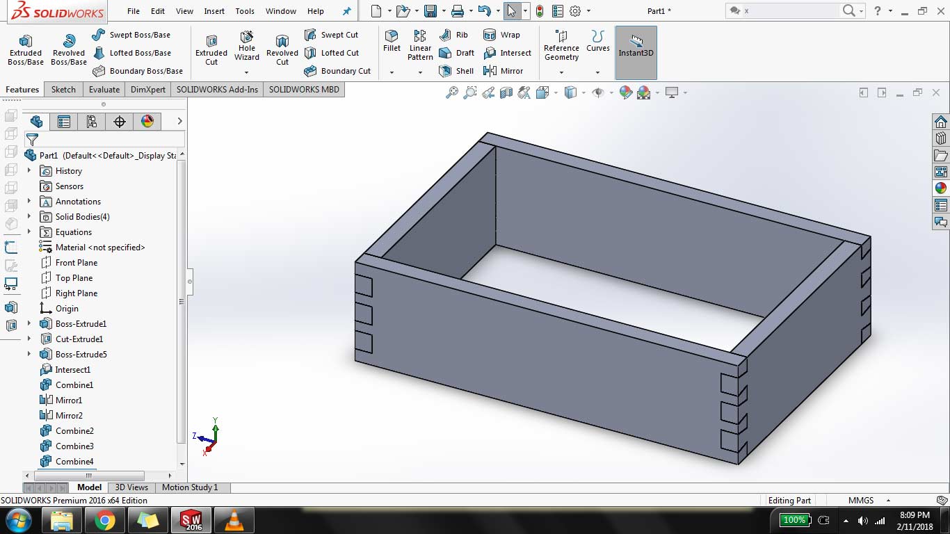
Make a sketch of rectangle box using global variables values and then click on "Extrude Boss/Base" button to make it 3D
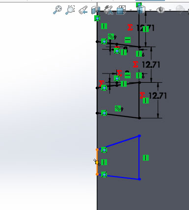
making dove tail joints on extrude part using line and smart dimension then cut the extra part using "extrude cut"
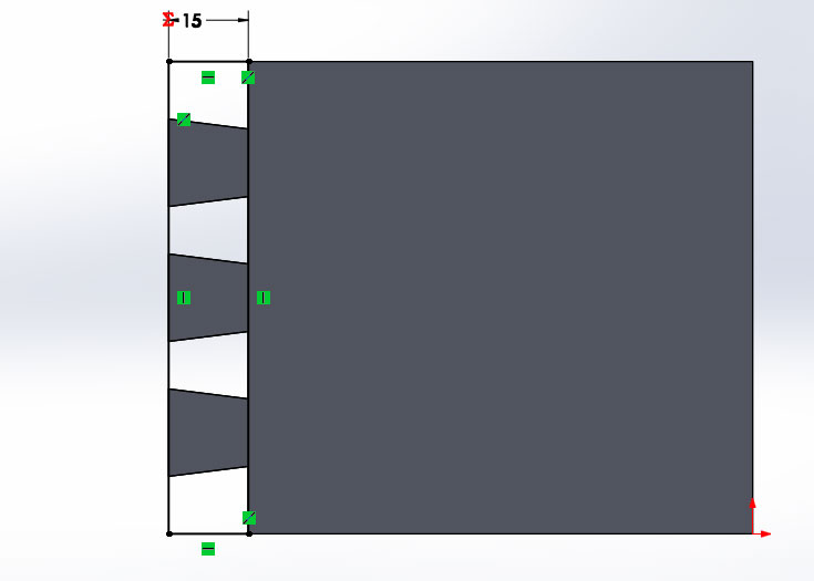
after extrude cut I make a rectangle on dovetail joint and align it with corners
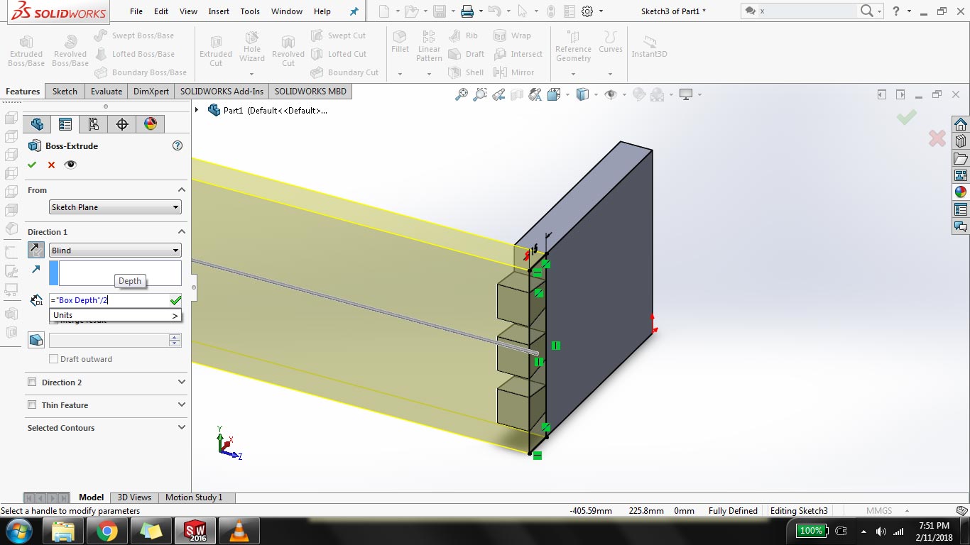
extrude the rectangle in half of box depth by unchecking "merge results"
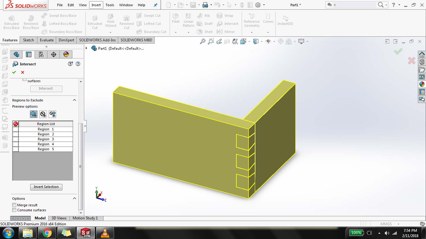
after extruding the new rectangle, these parts are connected so to cut parts from each other goto Insert> Feature> "intersect" check on "create both" and uncheck "Merge results"
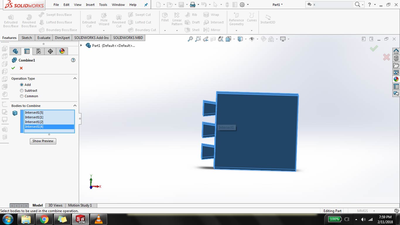
I have to split the part into 2 but it cuts in many parts, now to combine parts goto Insert> Features> Combine and select parts to combine
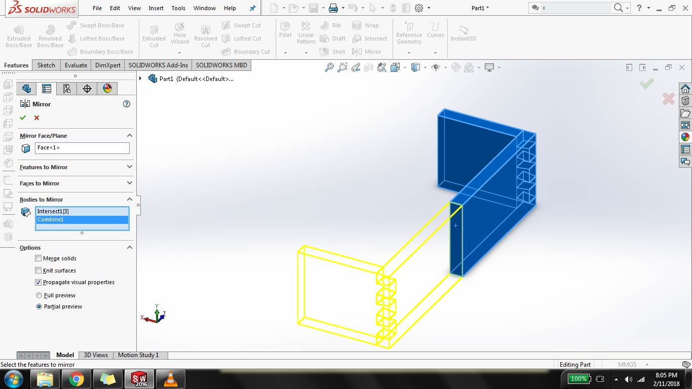
now to complete the box click on "Mirror" select "mirror face" then click on "bodies to mirror" and select bodies to complete the box
combine each side of block to make it one block using same combine feature use above
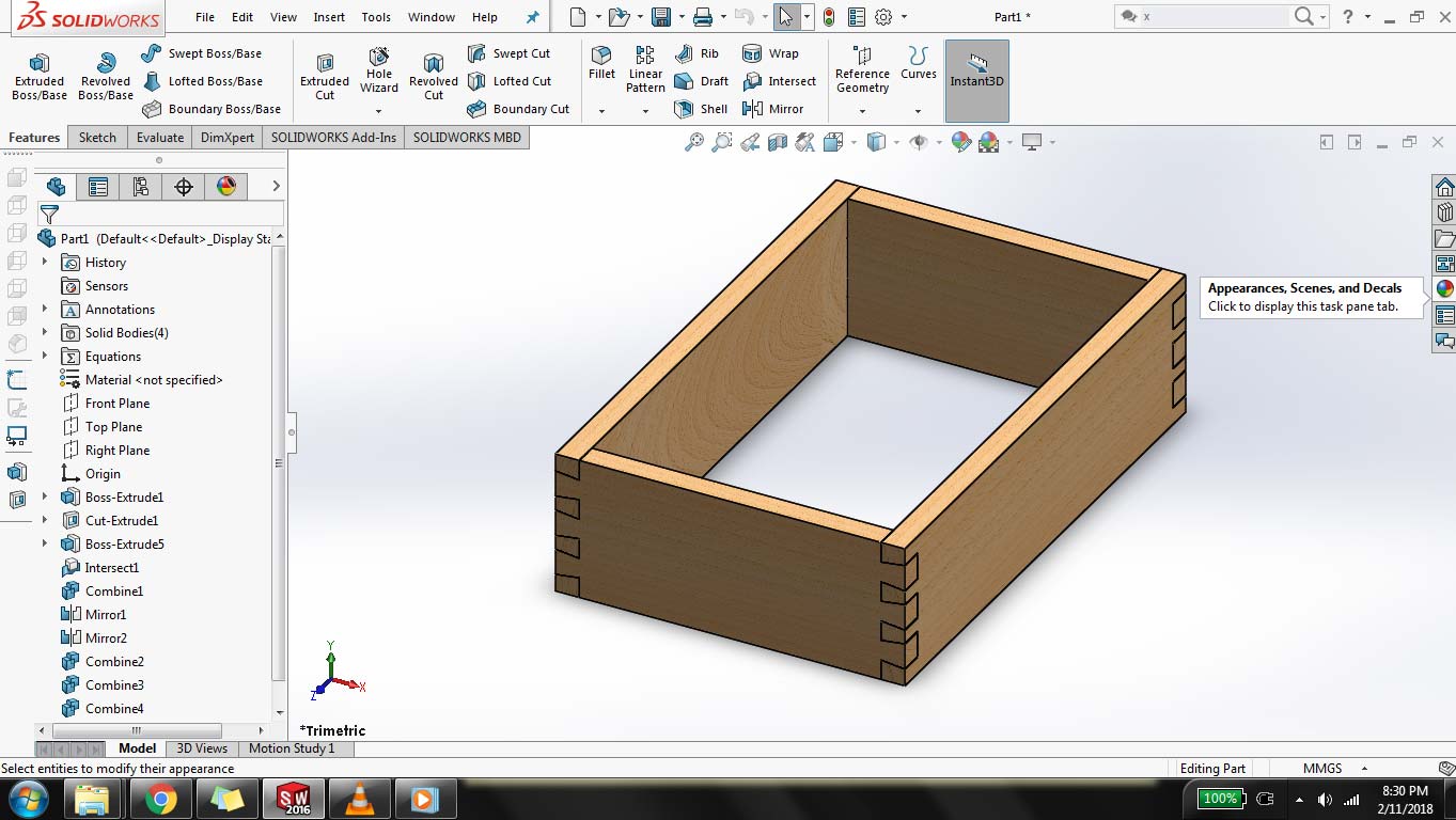
As for Final Touch I change the appereance to make it look like wooden beech by clicking on appearences and select wooden shades
"Click here"to download all files of this week

This work is licensed under a Creative Commons Attribution-NonCommercial 4.0 International License