


Computer-Controlled Machining
Tasks of the week
-
Group Assignment:
- Test Runout, Alignment, Speeds, Feeds, and Toolpaths for your machine Individual Assignment:
- Make Something BIG
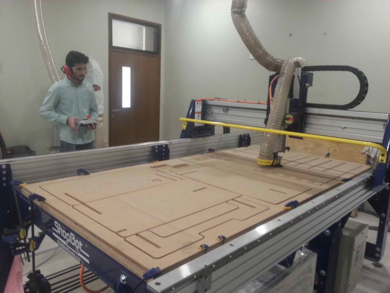
We are unable to do this week task on time because our ShopBot was not in operational condition, so we complete the work till designing and leave this week task until Mr. Francisco Sanchez who is in contact with our instructors come to fix the machine, and then suddenly in Week-12 he got the visa to visit Pakistan and came here to rescue our week-8 tasks. Not only how to run ShopBot, we learn many things from him.
In group assignment we did two things, as our machine is working first time, we need a flat surface platform for it. Second we make a test part which help us to set the size of slots in our Individual Assignments.
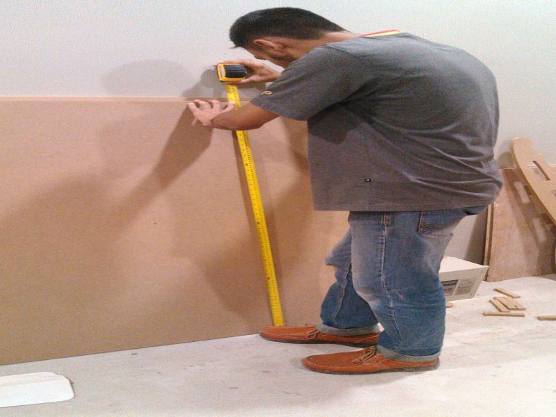
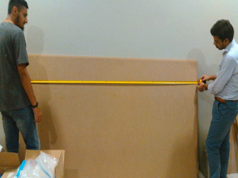
Taking Measurements
We are provided 8x4 ft 17mm MDF Wood boards for working on this week task,we use MDF board as platform for our Shopbot, but after checking the thickness we found that the board was not 17mm thick on each side.
We also measured the height and width of the board because while creating toolpath we need to feed these input also.
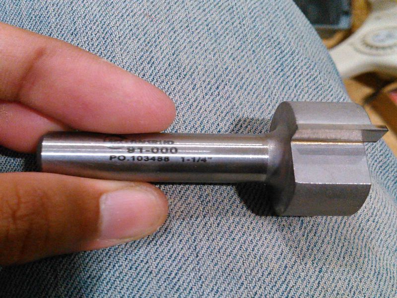
To make the surface flat we are using spoiler board cutter which shaves board to same thickness.
Generating Toolpath
We are using VCarve Pro Software to generate the G-Code for ShopBot, below we described each step for this process:
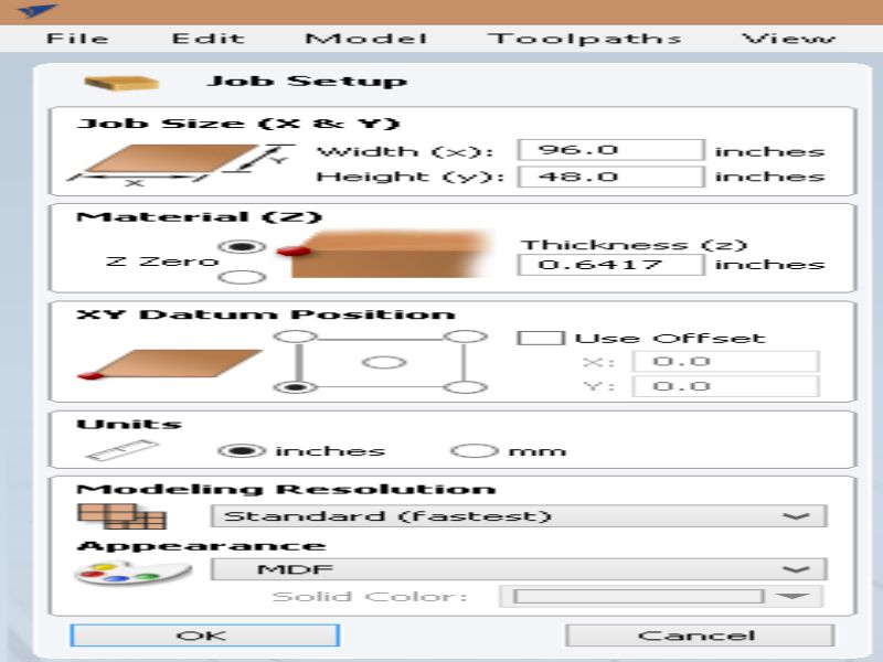
- Double click on VCarve to open it
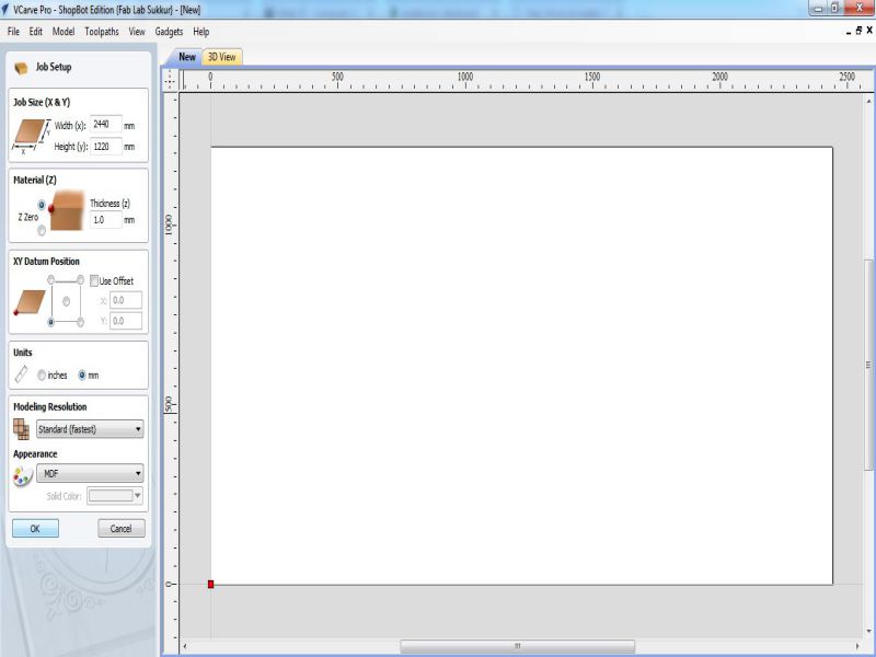
- Fill the job setup menu by entering board dimensions (width, height and thickness), set the XY Datum Position by clicking on bottom left corner, set units (our dxf files are in millimeter so we select "mm" in this column) and in last for appearence we select MDF because we are using MDF, then click "OK" for file operations.
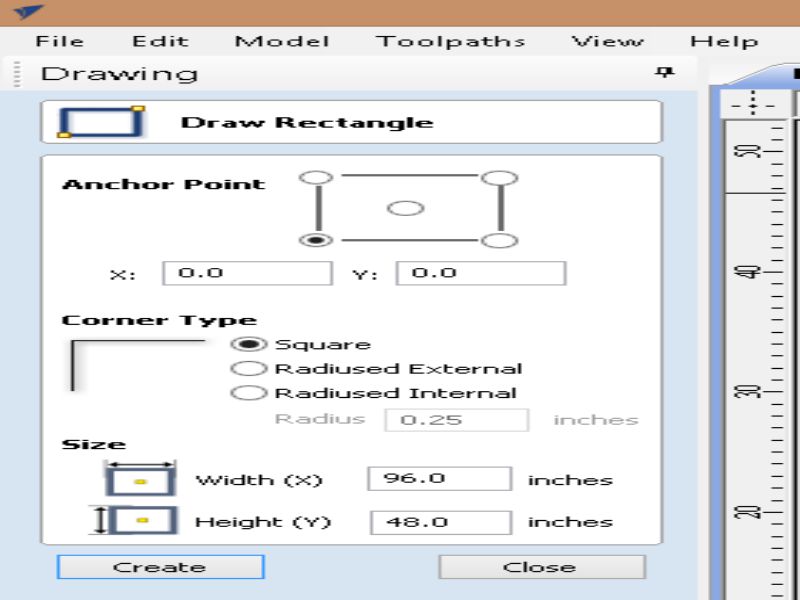
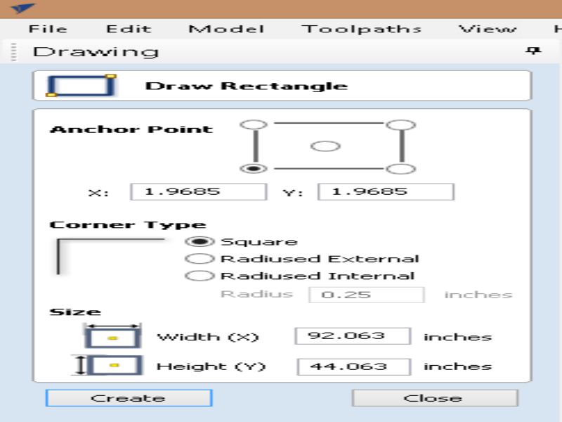
- To generate a toolpath a vector is required, so we draw rectangle on whole board.
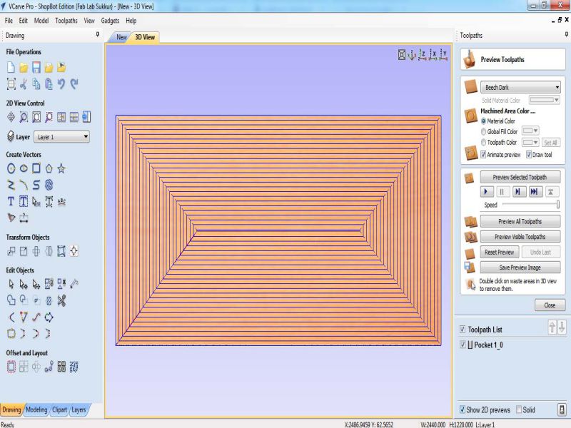
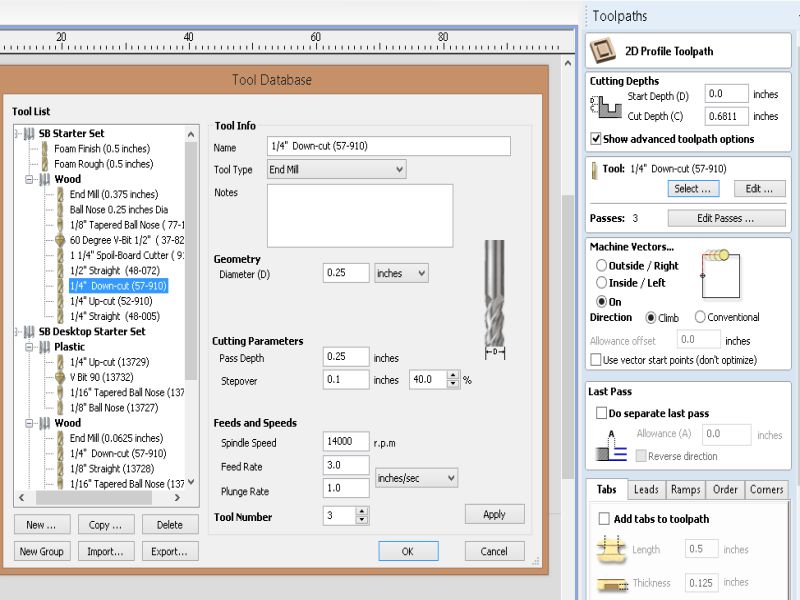
- after making vector now we are setting up the toolpath. Click on "Pocket toolpath" option in toolpath tab, then set the cut depth to "1mm" this shaves the whole board over 1mm, then select the "tool", in our case we select 1/4" Spoil-board cutter (the picture of the tool is mentioned above). Now select the vector, name the toolpath and click on "Calculate".
- After calculate the toolpath it is good practice to check the Preview of toolpath, if something is not shown right then change the settings and again generate toolpath.
- If everything is correct in preview save the toolpath by checking post processor and set it to the dimensions we use to make the file. and then click on "Save Toolpath(s) to File", this can generate .sbp file which is used by ShopBot as instruction to work on job.
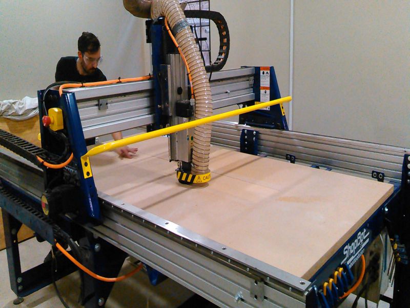
Generated .sbp file is given to shopbot, after setting x,y and z coordinates, we click on "Cut" in Shopbot panel to start the job.
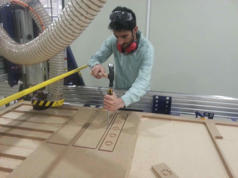
Making Test Part for Press-Fit
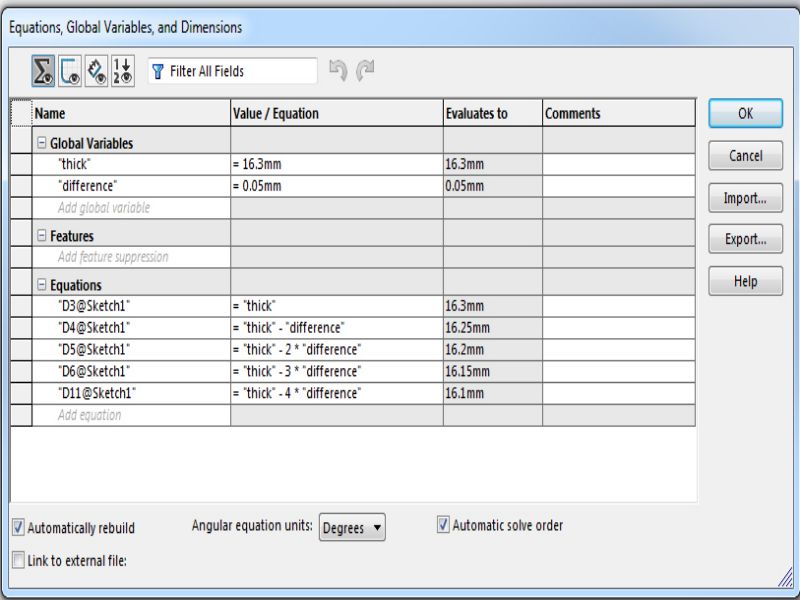
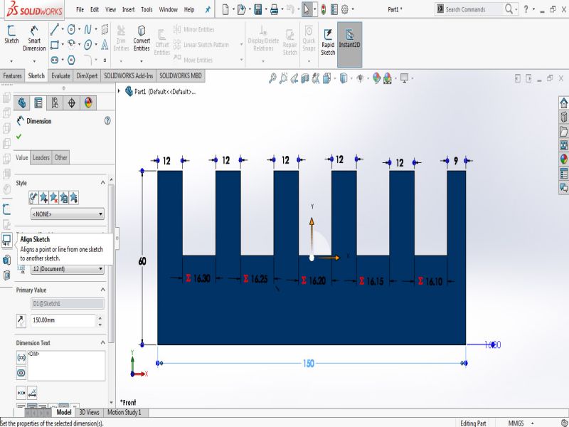
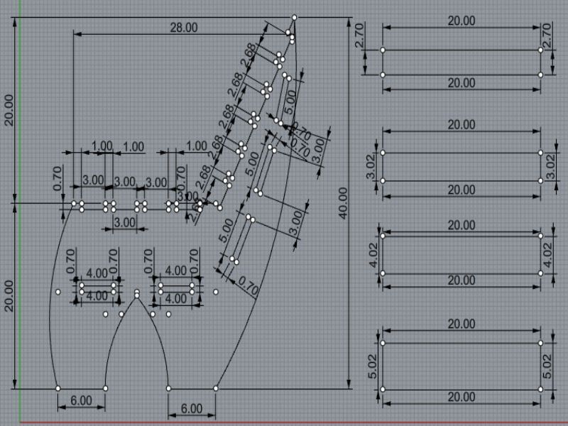
Most of our assignments are press fit so we made a test part with different thickness slots to check in which slot the wood is better press fit. The design is made in SolidWorks while using two parameters, one is average thickness of material and other is the "difference" which is used to set the slot sizes.
Using "Line" tool and "smart dimensions" we made this little piece of 60x150mm.
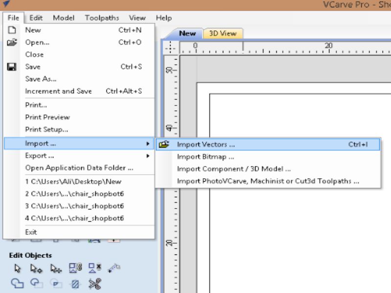
For VCarve we need a file in .dxf format and to make a dxf in Solidworks first we need to open the file in "drawing" window then save it as .dxf
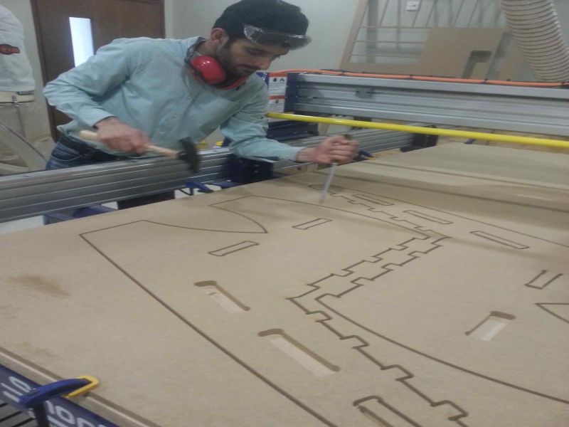
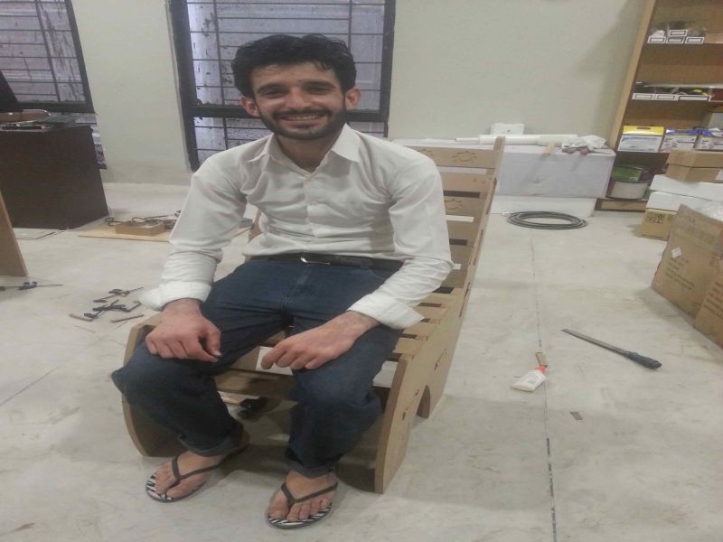
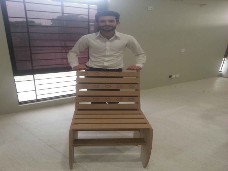
This week is amazing one, designing and making something on wood using shopbot machine. This week task is to design something big using shopbot machine which is
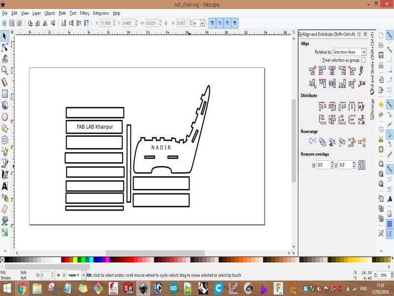
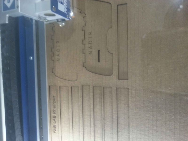
computer controlled wood cutting machine. For this I designed a Chair, I, then cut the designed chair on laser cutting machine using cardboard, for checking purpose.
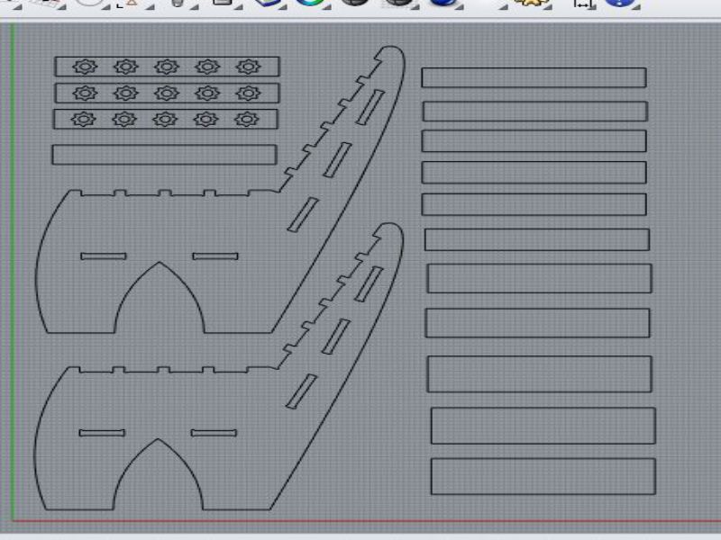
For cutting it on laser cutter machine on cardboard, I designed its layout on Inkscape software.
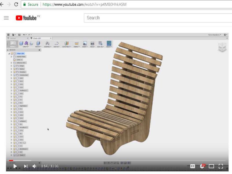
I got idaa of the chair from a video, the image is given below from which I tend my mind to design a chair similar to this one.
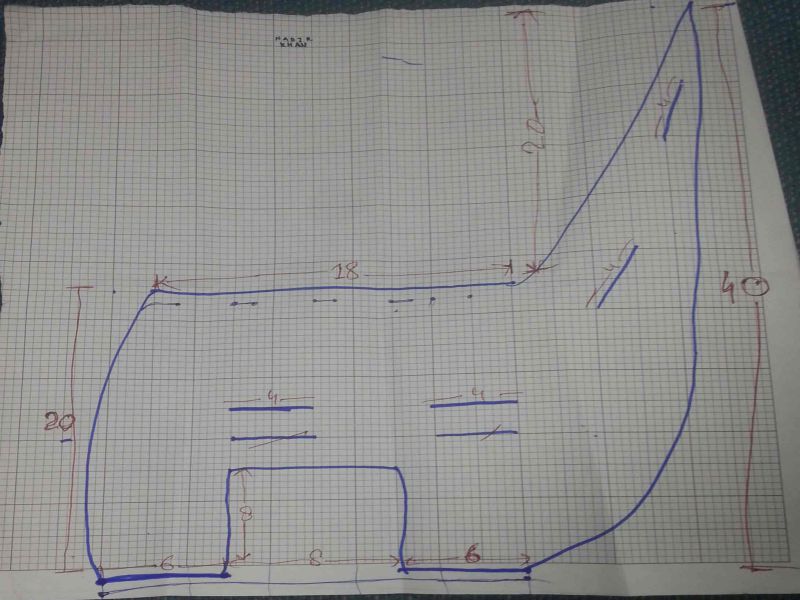
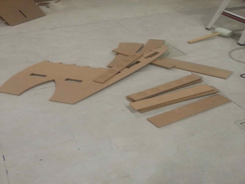
Following is the rough sketch, designed for laser cutting machine, I knew it needs changes after cutting it on laser cutter machine on cardboard.
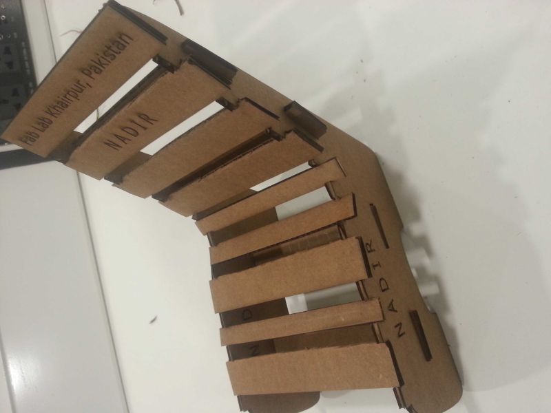
I noticed few changes in my first version of chair, so then I designed it accordingly. Below is the sketch of my model.
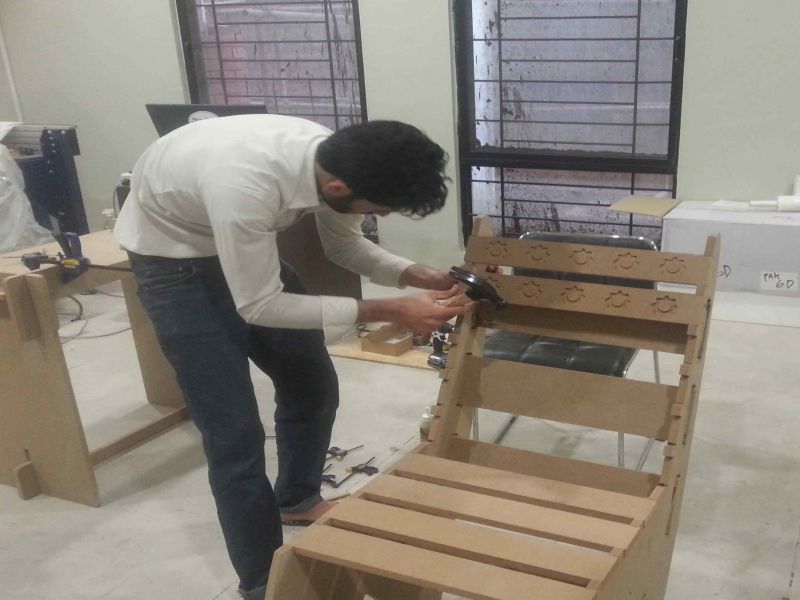
And, started designing it on Rhino CAD software. I download its trial version (Rhino 6) for 90 days and then installed it on my laptop. In last I came to a conclusion that working with rhino is good. As, Rhino has another facility of providing parametric modeling through 'Grasshopper'. Grasshopper is a plugin to do parametric modeling in Rhino environment. So, I started designing it here on Rhino6's environment, where many times I stucked then watch tutorials to get my desired edge of designing. It was a good experience of making a design which is in your mind, so this did not bothered me.
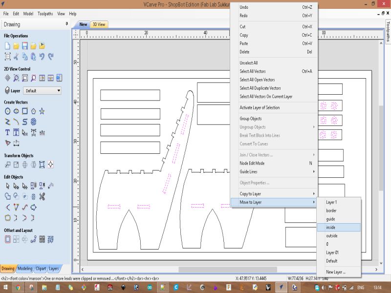
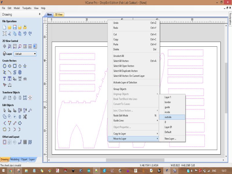
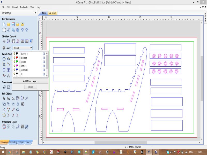
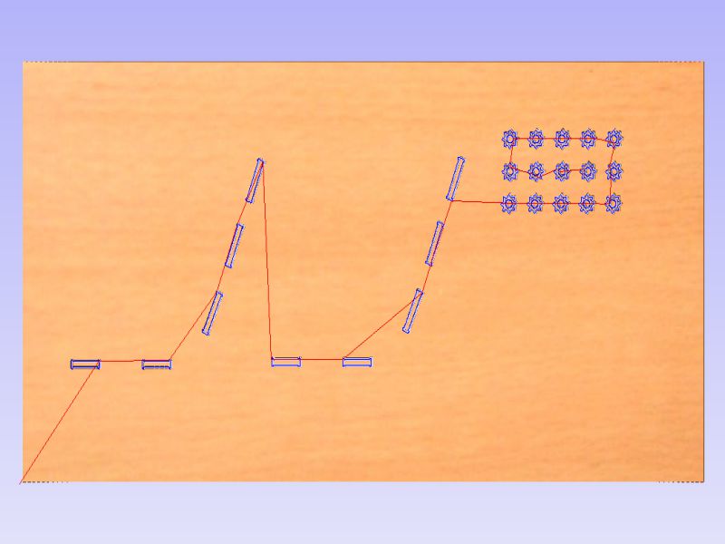
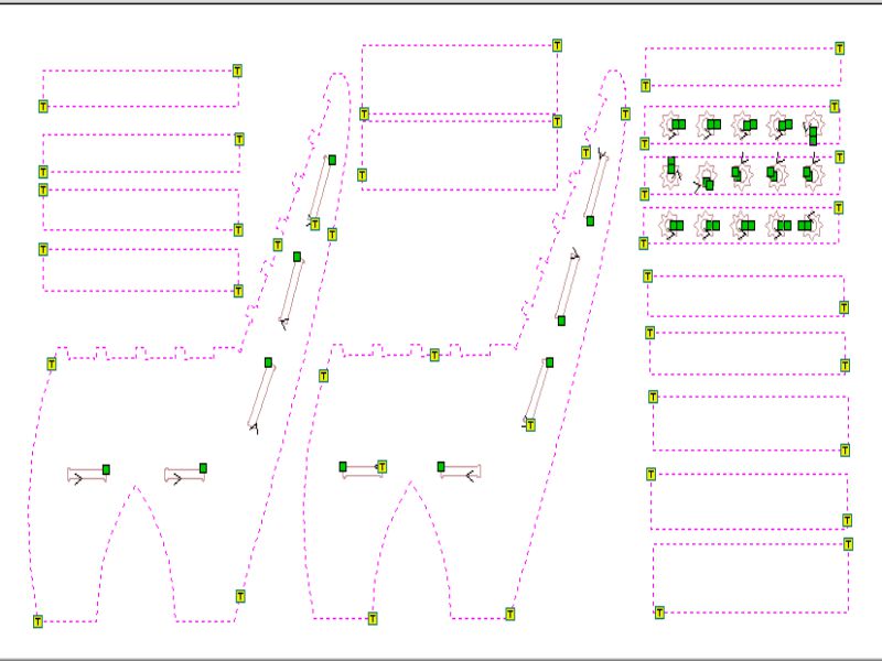
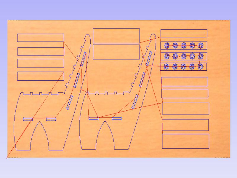
After finishing the designing process in Rhino 3D, I exported .dxf file for opening it in Vcarve. Vcarve is a software which provides us to solutions of cutting parts in our CNC machine. This software can import 2D designs from other programs and also provides the full set of drawing and editing tools. For 3D we can rough and finish the model, which we will use in Composite week's task. So, I imported the .dxf file in Vcarve file for further process.
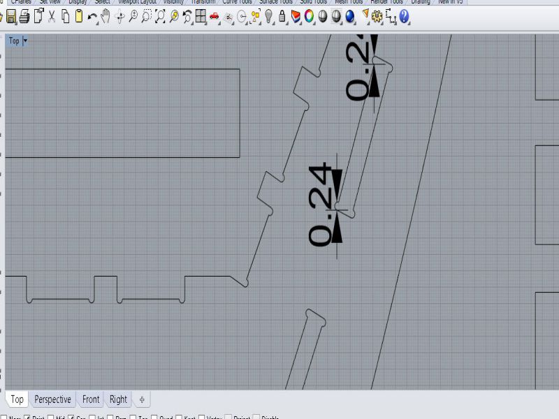
Below images best illustrates the steps of generating toolpaths for final cut in shopbot.
Download all files from here

This work is licensed under a Creative Commons Attribution-NonCommercial 4.0 International License.