Embedded Programming
This week's assignments were:
- Read a microcontroller data sheet.
- Program your board to do something, with as many
different programming languages and programming environments as possible.
Read A Microcontroller Data Sheet
Reading and
understanding both the microcontroller data sheet and the ISP header is
essential because, they both have important functions that can
facilitate the development of solutions using Arduino ATtinys. I found
the microcontroller data to be very thurough and organized. Here are
some of the examples of information which I found to be important and
also interesting. The reason that I found this information to be
important is because these are the essential pins that control your
board.
VCC: supplies voltage
GND: ground
RESET: reset input
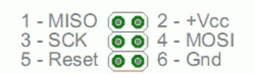
MOSI: The master sends data to the peripheral
MISO: The master receives data from the peripheral
SCK: The master controls the pulse / clock of the connection
In the picture below you can see the board schematic.
Note that the PA3 pin correspond to the LED.
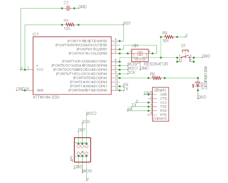
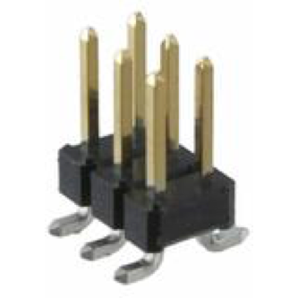
As you can see in the image bellow the ICSP Header has six pins in two sets of three.
Programming The Board To Do Something
During the
electronics design , I made the Hello World board, but I didn’t program it
yet. I started with a button and one LED. First I downloaded and
installed a lot of software that was mentioned in the class. Since I
have Macbook, I downloaded and installed the Crosspack AVR and then
XCode from the app store. I followed this tutorial:
http://archive.fabacademy.org/archives/2017/doc/programming_FabISP.html
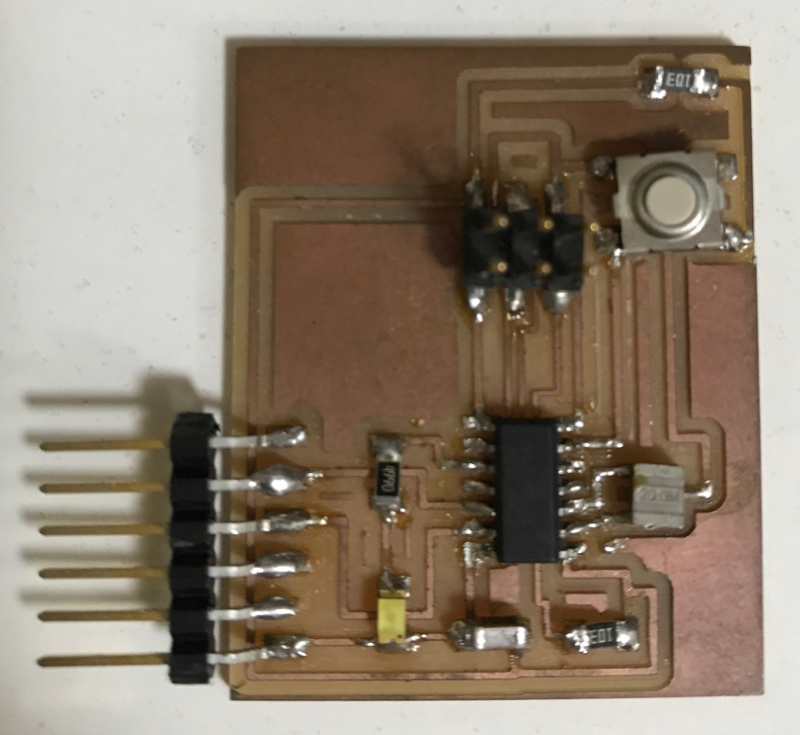
In the picture below you can see my board I made in the electronics design week:
I already had the Arduino Software, because I used it for the electronics design
assignment. The first step was to configure the Arduino IDE to use my
USBTiny and to be able to program a ATTiny84 microcontroller. I
followed this tutorial on how to do it:
http://highlowtech.org/?p=1695.
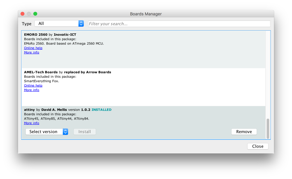
I followed these steps:
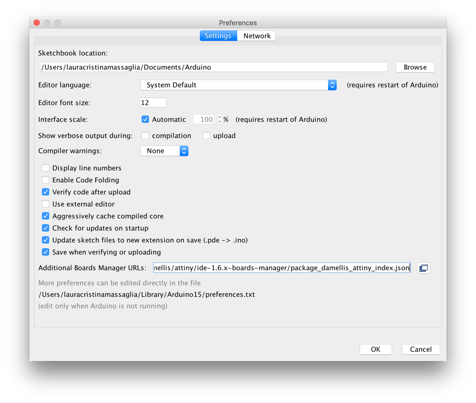
1. Open the preferences dialog in the Arduino software.
2. Find the “Additional Boards Manager URLs” field near the bottom of the dialog.
3. Paste the following URL into the field
(use a comma to separate it from any URLs you’ve already added):
https://raw.githubusercontent.com/damellis/attiny/ide-1.6.x-boards-manager/package_damellis_attiny_index.json
4. Click the OK button to save your updated preferences.
5. Scroll to the bottom of the list; you should see an entry for “ATtiny”.
6. Click on the ATtiny entry. An install button should appear. Click the install button.
7. The word “installed” should now appear next to the title of the ATtiny entry.
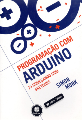
I’m a beginner at programming. As I mentioned before I have had only
some classes at my university. This helped in my decision to read and
study more about this subject using a book on how to program with
Arduino. Here below there is a picture from the book that I read.
After I read and
understood a little better about the subject, I opened the Arduino
software and started programing. My instructor gave us a paper on how
to use Arduino as ICSP Programmer for ATTiny45/85.
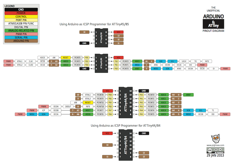
Once, looking over
the diagram the instructor gave us I had noticed that my LED was at pin
3 and my button was at pin 7. Then I used the ATtiny84 and the
configuration as you can see in the image below:
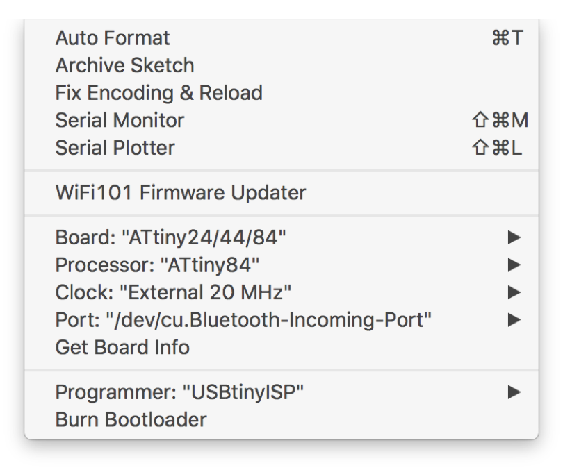
Below there is a list on how to configure ATtiny84:
1) Select the board: Actually you select the category of microcontroller
2) Processor: Select the type of microntroller we only have the Attiny 84 in our lab, because the memory is bigger than the 44
3) Clock: Select the clock that you used to make your board. As I used an external oscillator with 20MHz, I used it.
4) Port: It usually recognizes automatically, you just need to select it
5) Programmer: Its necessary to select USBtinyISP. That’s the one refereed to the Fab ISP that I used
After that we need to compile clicking the “V” button. The compilation checks the programming and some errors.
Before upload and program it, make sure the FabISP and the board are
properly connected to your computer. You also wants to make sure that
your board and the FabISP pins match one to another. The
connector can be inverted because of the ICSP header, and if its
happen, the programming will not work
Then click “Upload ->” to program the board. If everything is fine then you receive no errors.
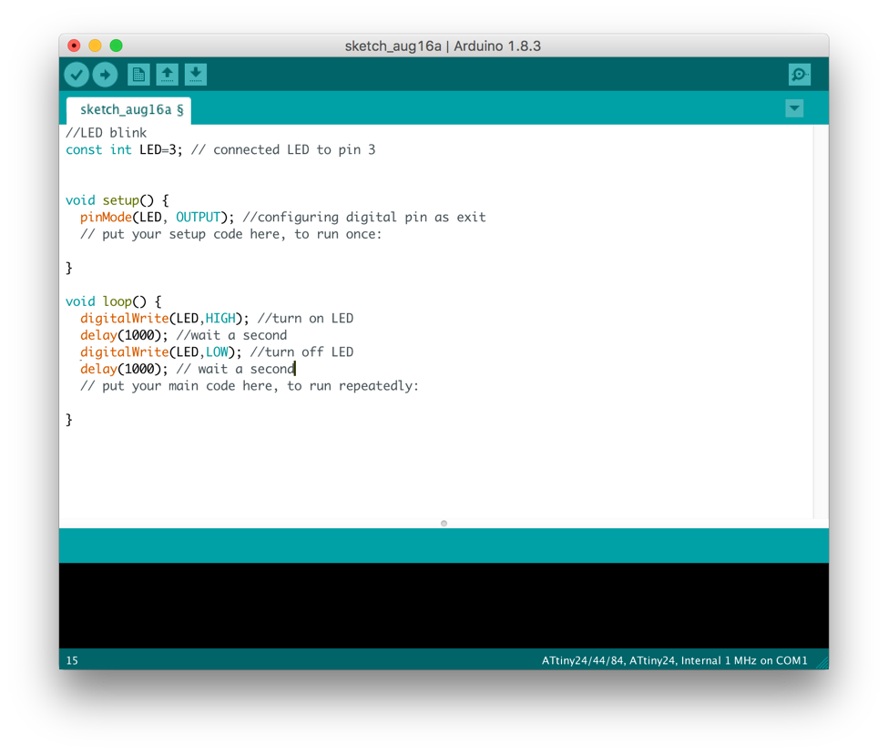
My idea was to program something simple, since programming for me is
very hard. My first attempt was programing my LED to blink and it was a
successful attempt. See image below:
The next step was
to program the button. On my first attempt to program the button it
didn’t look the way I expected it, because when I connected the USB
cable to my computer the LED light was already on. When I pressed the
button the light went out. As you can see in the video below:
https://youtu.be/Y6KYqWusZLw
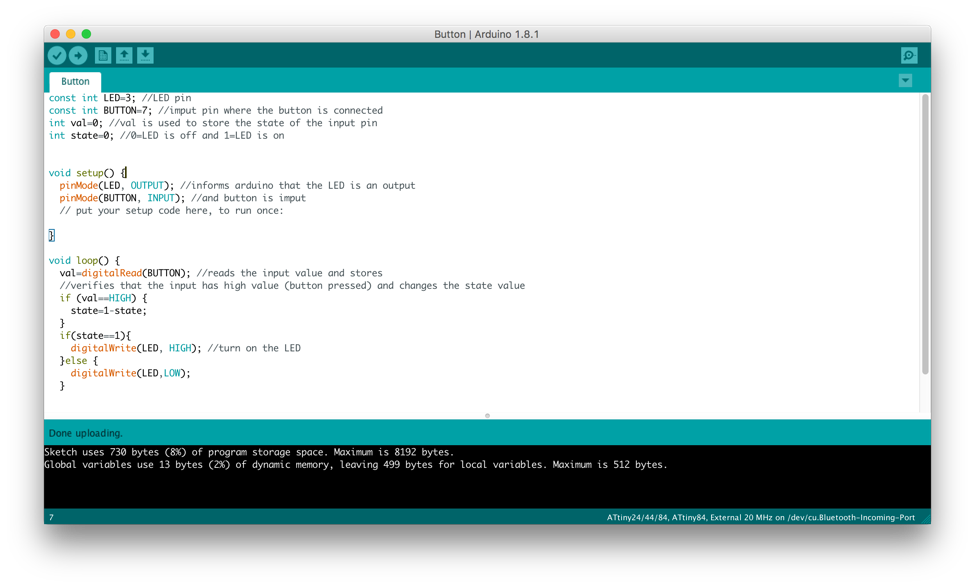
I realized that there was something wrong, because my initial idea was
the opposite. The way it was supposed to work is when I pressed the
button the LED Light would turn on. Below is an image of my first
attempt at programing the button:
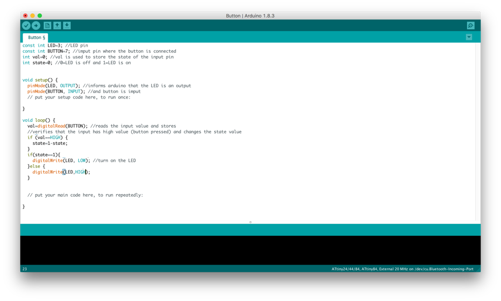
I didn’t know what was wrong. So then my next attempt was to change the
last “digitalWrite(LED,HIGH)”; for “digitalWrite(LED,LOW)”;
and “digitalWrite(LED,LOW)”; for “digitalWrite(LED,HIGH)”. As you can see in the Image below:
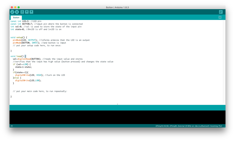
It didn’t solve my problem. So, I went back and decided to carefully
read the program again and I realized that I didn’t need to make those
changes because the problem was in if(val==HIGH). Instead of HIGH I
needed to change to if(val==LOW) because the button was connected on
the ground and not on VCC. As seen in the image below:
After I fixed the error my program finally worked. When I connected the
board with my computer and pressed the button, the LED turned on, as
you can see in the video link:
https://youtu.be/-TZJpLVlcNE