We got an
introduction to Eagle (Easily Applicable Graphical Layout Editor) in
our class. It is a flexible and expandable EDA schematic capture, PCB
layout, autorouter and CAM program.Click on here to read a tutorial:
http://archive.fabacademy.org/archives/2016/doc/electronics_design_eagle.html
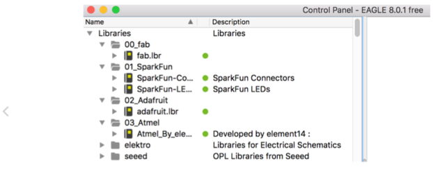
To add the components you will need the "fab" and the "supply" libraries. The "fab" library can be downloaded
here. The "supply library is already standard on the Eagle software.
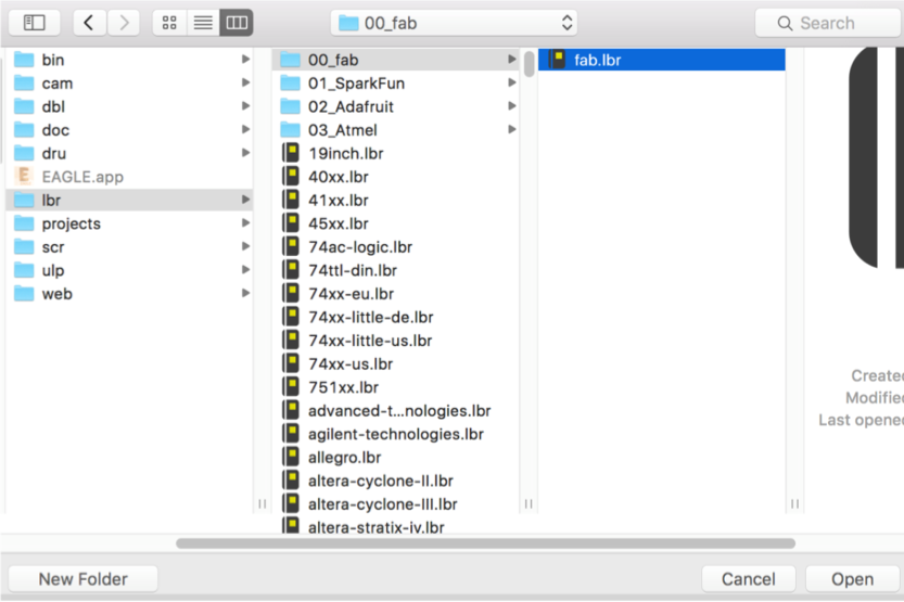
Here is how to install the libraries:
• On the Mac, it should be /Applications/EAGLE-8.#.#/lbr/
On Windows, it is most likely C:\Program Files\EAGLE-8.#.#\lbr\
On Linux, the default install location is /opt/eagle-8.#.#/lbr/
• Go to the top toolbar and select the "Library" menu
• Select "use" and open the .lbr file you downloaded.
Now when you go to add a component- all of the libraries are available.
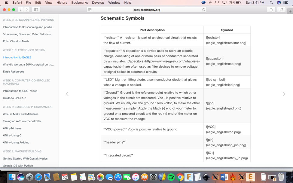
After that, I started doing the schematic.
schematic: A
schematic in electronics is a drawing representing a circuit. It uses
symbols to represent real-world electronic components. The most basic
symbol is a simple conductor (traces), shown simply as a line. If wires
connect in a diagram, they are shown with a dot at the intersection.
Here below is a description about the symbols.
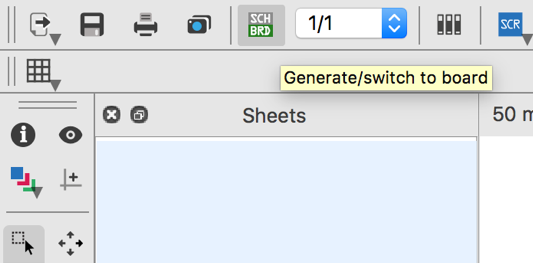
Eagle has two windows that you use simultaneously to design a board:
1) Schematic (.sch) - logical components
2) Board Layout (.brd) for the actual board that we mill
There is a schematic / board button

so you can switch between the two as you can see in the image below.
NOTE: Never
close layout and not schematic or vice versa. You need to keep both
open all the time. Closing one view while the other view is open (and
making edits) will break the link between the two.
There are 2 ways you can interact with Eagle one is though the
Graphical Icons Toolbar (image below), and the odder ins, which, you
can type a command at any point, then select the item in the schematic
/ board that you wish to interact with, see section on commands after
the picture below.
Commands:
• add = opens up the libraries so that you can add components in Schematic view
• move = moves an item
• net = makes a logical connection
• junction = adds a junction
• value = adds value to components (i.e. ohm rating)
• name = names a component
• label = displays the name of a component in schematic view
• copy = copies an existing component on the schematic.
• route = used in Layout view, this tells you if you need to add a connection (follow yellow lines)
• ERC = electronic rules check; this ensures your board will actually work (use in schematic view)
• DRC = design rules check (in board view) - keep all
the default settings (16 mil is fine); it should display a "no error"
message in the bottom
left hand corner of the screen
• group = groups components in Layout view together;
if you right-click, then you can choose Move: Group to move the grouping
• rats = in board view, tells you if you have airwires
• rip = deletes connections in layout
• show = after typing this, select a component to see
information about it displayed in the bottom left corner of the screen.
Also, if you type
show + [name of component] you can see that component highlighted. You
can use this to see all the ground traces, for example.
• text = allows you to add text to your board. You
can also edit the exported .png file in The Gimp to give text and black
and white line
images. I recommend adding text in The Gimp.)
• info = then click on text to get properties of the text
After all these steps you can start using Eagle.
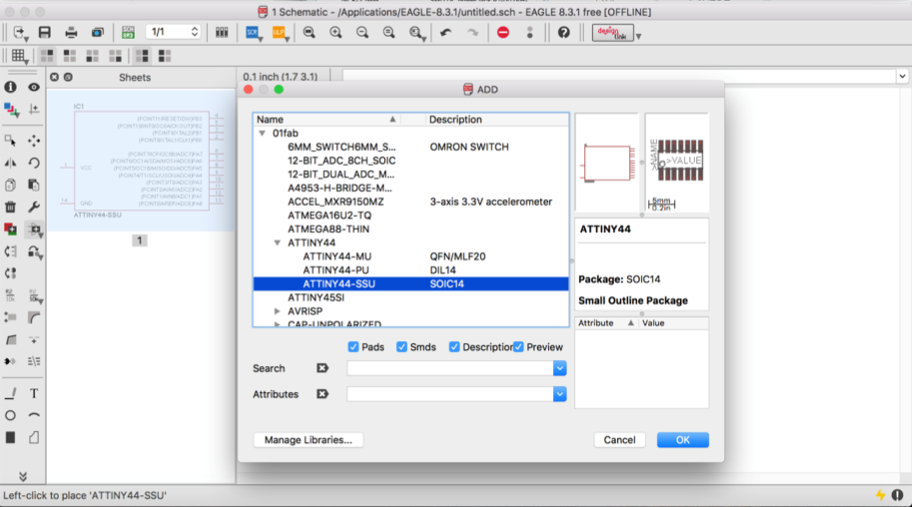
Adding Components:
Add a component (either type "add" or select the "add icon from the
toolbar". The add menu will open. You can either look through the
listed libraries for a component to add or you can type it into the box
above the "drop" button.
For example: Add ATTINY 44- SSU (in the fab.lbr library which is the same one I used)
Adding Components:
There are two ways to connect components in a schematic:
1) First you can connect the
components with a wire (also called a "net" in Eagle). This may make
connections obvious at first, but can
get really messy quickly as nets cross over each other.
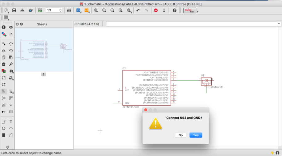
2) Or you can also name the nets
attached to components that need to be connected by naming them with
the same name. See example
schematic
above. Eagle will ask you if you want them to be connected (type yes).
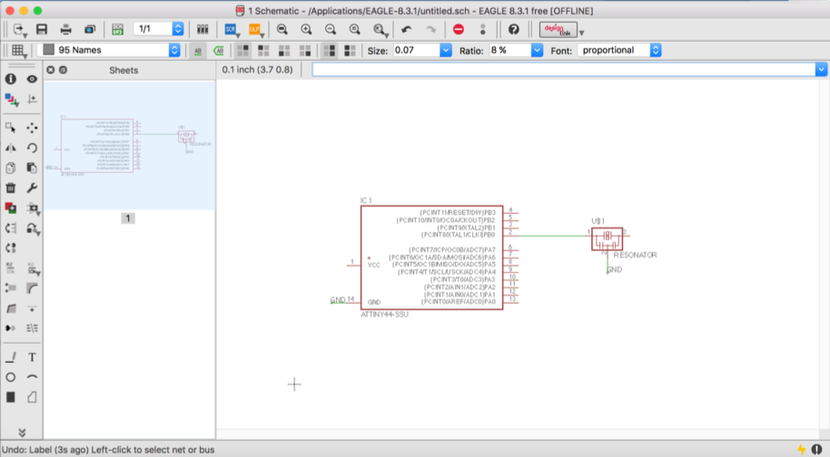
After you name the component - label it so the name
appears in the diagram.
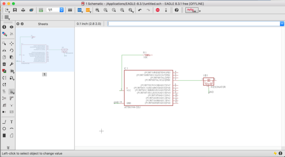
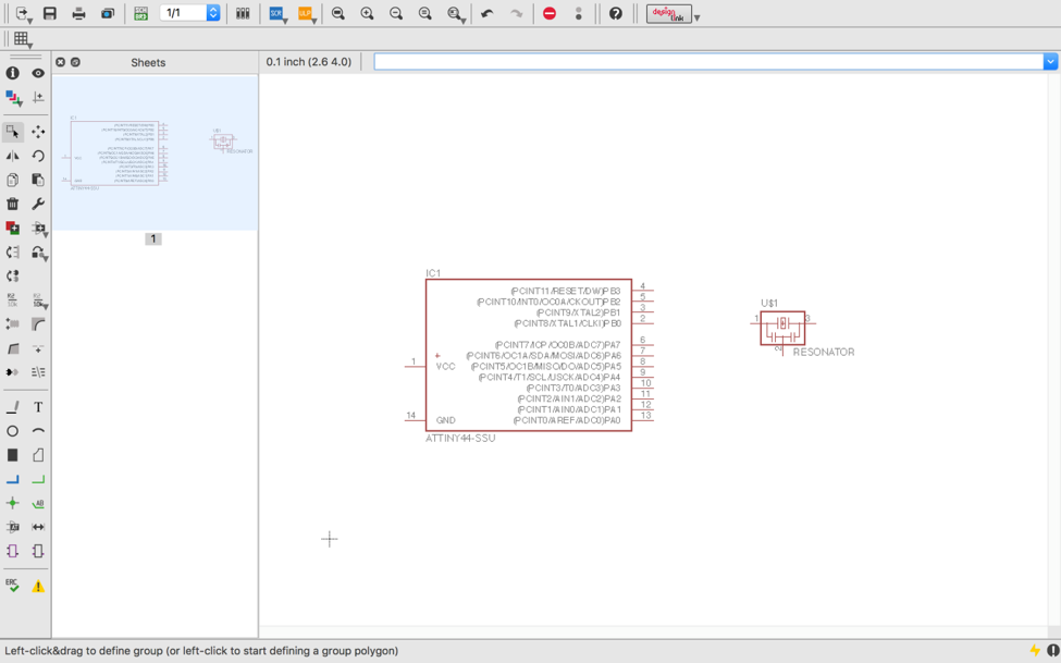
As you can see in the image below, I wanted to connect the pin 14 in
the attniny with the pin 2 in the resonator, so I created a line in
each one, and then I typed in name and enter, then I clicked on the
green line (14) and I typed GND, I also did that to the line (2) and
typed GND, then the Eagle asked if you want to connect both lines, now
the lines are connected. You can also connect the pins with one line,
as you can see in that I connect the pin (2) in the attiny with the pin
(1) in the resonator.
To show the names in the green lines you need to click on Label in the
tool bar, then you click on the green line 14 for example and is going
to show you the name you put already, you should also do it for the
line 2 in the resonator. Now you know both are connected, even though
you don’t see a line between them.
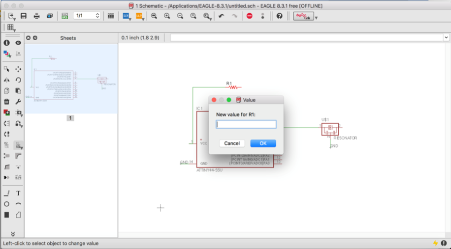
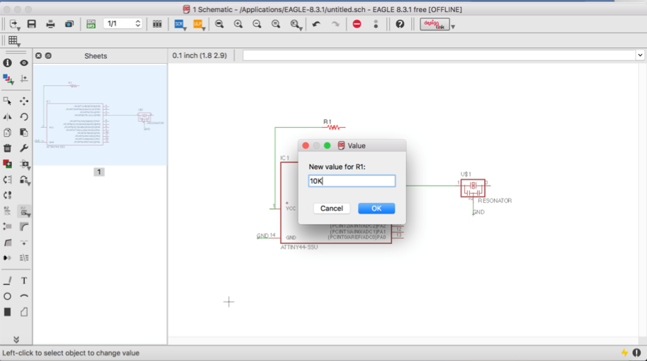
Now it was time to add a resistor and I wanted to connect the resistor
with the VCC (pin 1) in the Attiny. I created a line between them. Now
I needed to put the value in the resistor, by typing value> enter,
then you click in the resistor, it will open a window for you to type
the value.In this case my resistor had a 10K value, so I typed it. After that you press ok, then the resistor now has the value
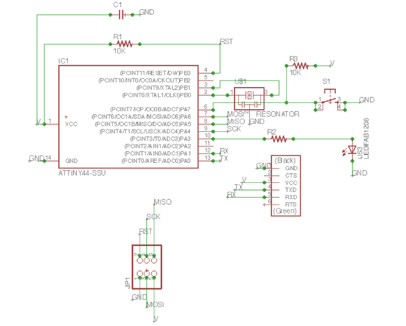
This is the schematic for "Hello Echo" that I drew:
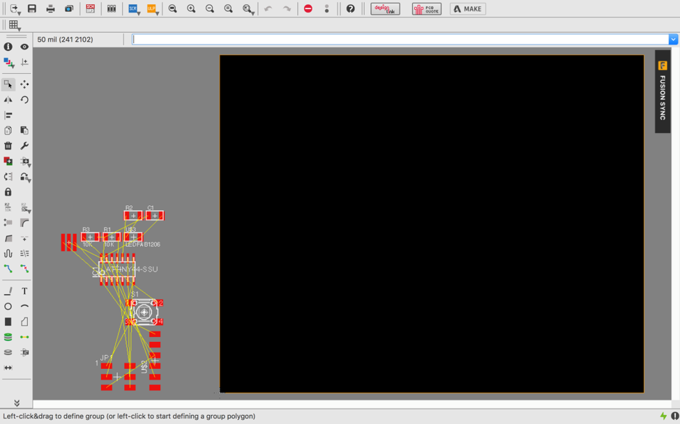
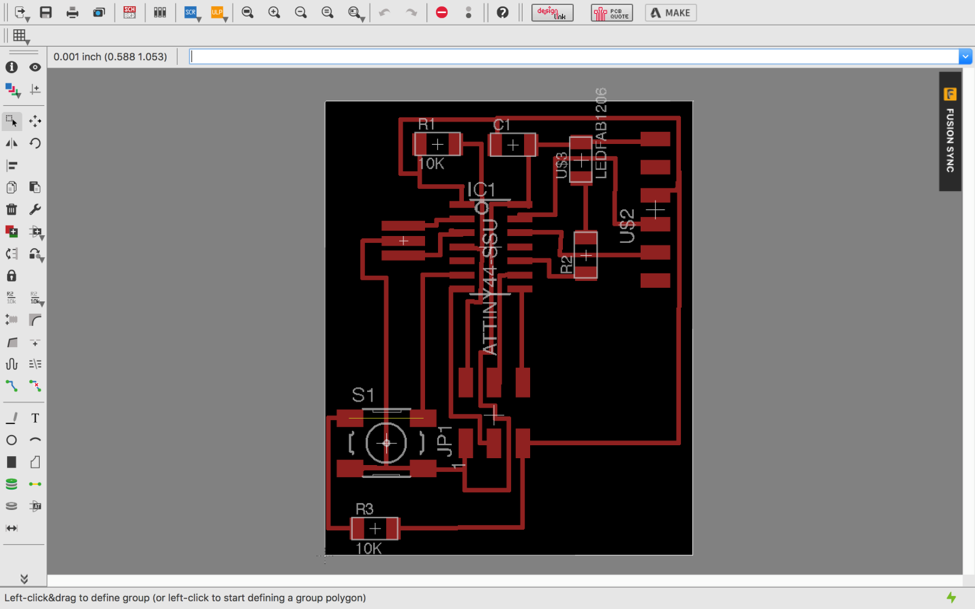
After connected all the components, I switched to board and I could see all of none routed paths.
 Routing:
• Use "move" to move each individual component around.
• Use "route" to route each trace. The wire will turn red as you route it into place.
• After you route wires, you can use the "move" tool to move them around as lines.
• Route all the traces until it looks something like the diagram below.
• There is also an autorouter
feature - it is good for making a general layout, but you will probably
have to edit the traces manually. Especially on this
circuit.
• To use the autorouter go to: the "tools" menu in the top toolbar and select "auto".
• You can also type "auto"
• It doesn't have to look exactly
the same, there is more than one way to route the traces. Just
use this as a guide.
If you do not see it, go to "Layers" and select "Unrouted". Use the
"Move" tool to position your components. After that try to route your
connections using the tool "Route". You need to figure out how to
connect them all without crossing paths to other connections. Below you
can see the routed board:
My first challenge was to put the routes in the positons that I wanted.
I had a problem that the route was crossing in a wrong way, but after
some tries I got it done. After you route your board you need to check
the design rules.We need to check that the endmill we are using (1/64
usually) is able to go between all the traces so the machine is able to
cut the board successfully. For this process we are going to use Design
Rules Check (script) that will check that there is enough space
everywhere.
Download the DRC script from
here:
• Type in EagleCad drc and press enter.
• A new dialog box should appear where you can LOAD the script.
• If everything is correct no error messages should appear.
• In case some red areas appear
between the traces, you should move the traces leaving more space
between them.
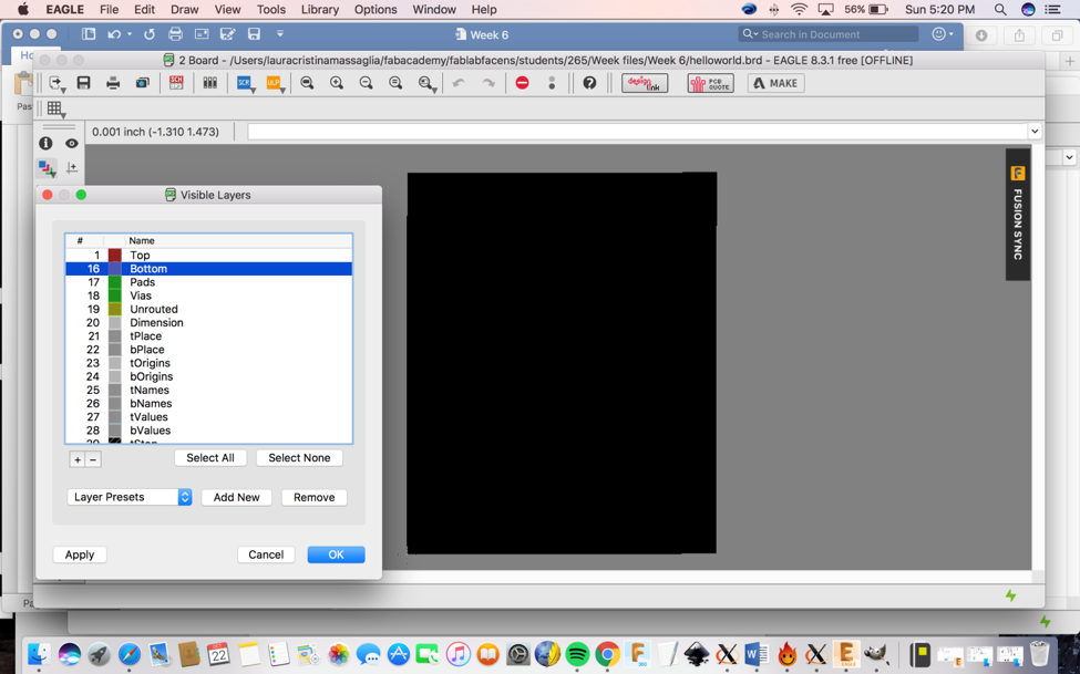
After you check the design rules you need to export the board.
Milling:
• First go to the layers
menu in the top toolbar, select the only the top layer (traces only)

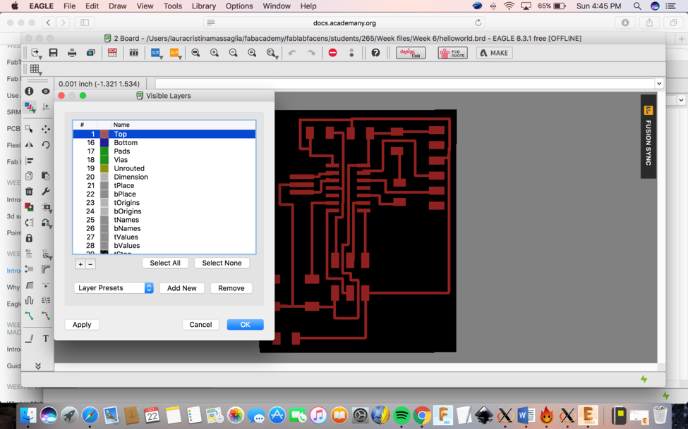
• Then export as a png (file > export > image)
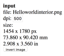
• Settings should be MONOCHROME and 500 DPI - this will export an image with white traces.
• You need to make sure the color mode is set to greyscale: image > mode > greyscale
• Then export Dimension layer for milling the outside of the board
• Remember the Modela cuts out the dark and white.
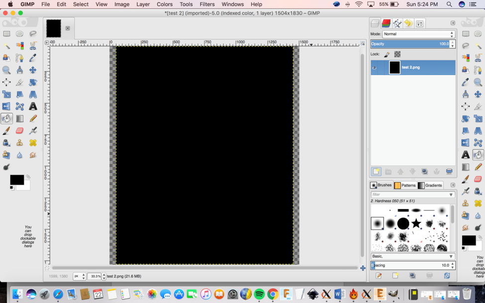
Then using Gimp I generated the interior and exterior of my board.
The Interior:
1- I first opened the file that I exported from Eagle.
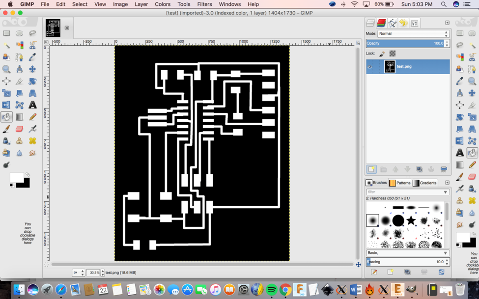
2- Then I clicked on
Image> Canvas Size and then I added 100 to the width and height,
then I clicked on center and ok.
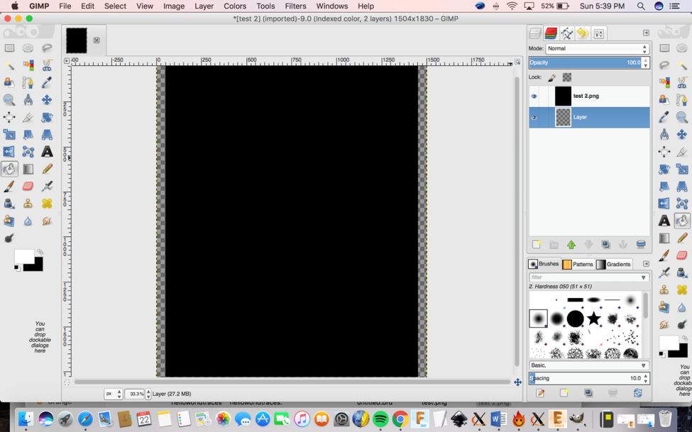
3- Create a new layer and put the layer above the image.
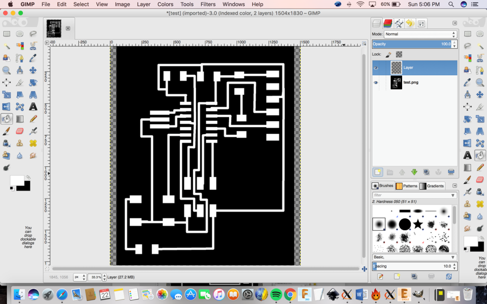
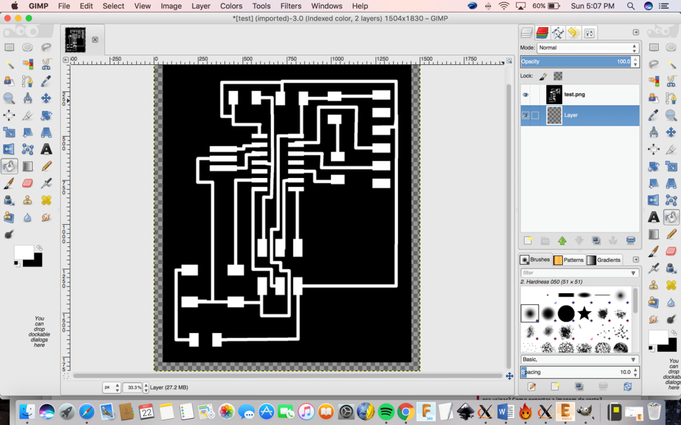
4- Then I needed to make the
checkered grey layer all black by selecting the bucket fill tool and
selecting the color black.
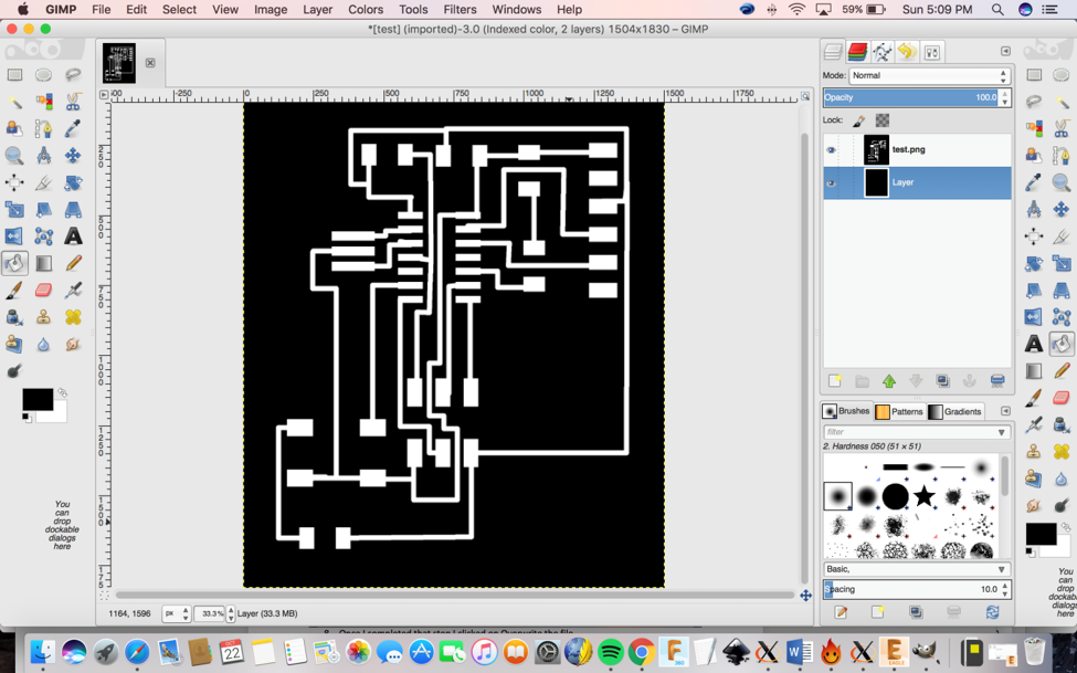
5- Once I completed that
step I clicked on file> overwrite the file. Now you have the image
ready to go on the fabmodules.org
1) You go to www.fabmodules.org
2) You click on image (.png)> Rolland mill
(.rml)> PCB traces (1/64)
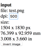
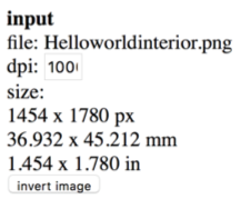
3) Since I use a Mac Book, I needed to change the dpi
500 to 1000 because of the size.
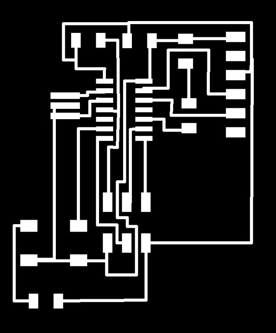
After I finished making all the routes as I wanted, I exported the
images to mill on the Modela. Here’s how the first attempt looked like:
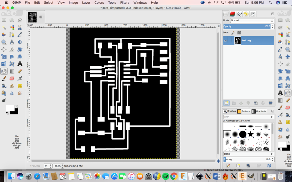
 The Exterior:
First go to the layers menu in the top toolbar, select the only the top layer (traces only)
1- I first opened the file that I exported from Eagle.

2- Then I clicked on Image>
Canvas Size and then I had to add 100 to the width and height, then I
clicked on center and ok.
3- I then created a new layer and I put the layer above the image.
4- Then I selected the “Bucket fill tool” and paint the image in white and layer in black.
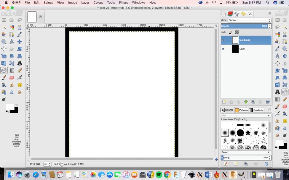
5- Once I completed that step I
clicked on file> overwrite the file. Now you have the image ready to
go on the fabmodules.org
1) You go to www.fabmodules.org
2) You click on image (.png)> Rolland mill
(.rml)> PCB traces (1/64)
3) Since I use a Mac Book, I needed to change the dpi
500 to 1000 because of the size.
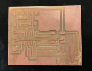
After I made all the routes as I wanted, I finally finished and
exported the images to mill on the Modela. Here´s how the first attempt
looked like:

I then milled it, cleaned it and started soldered the components on to the board.
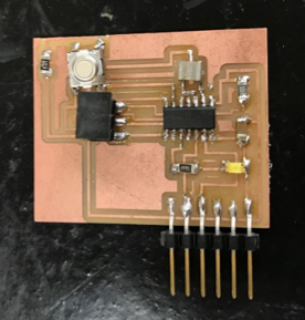
I programed the board in this
week.
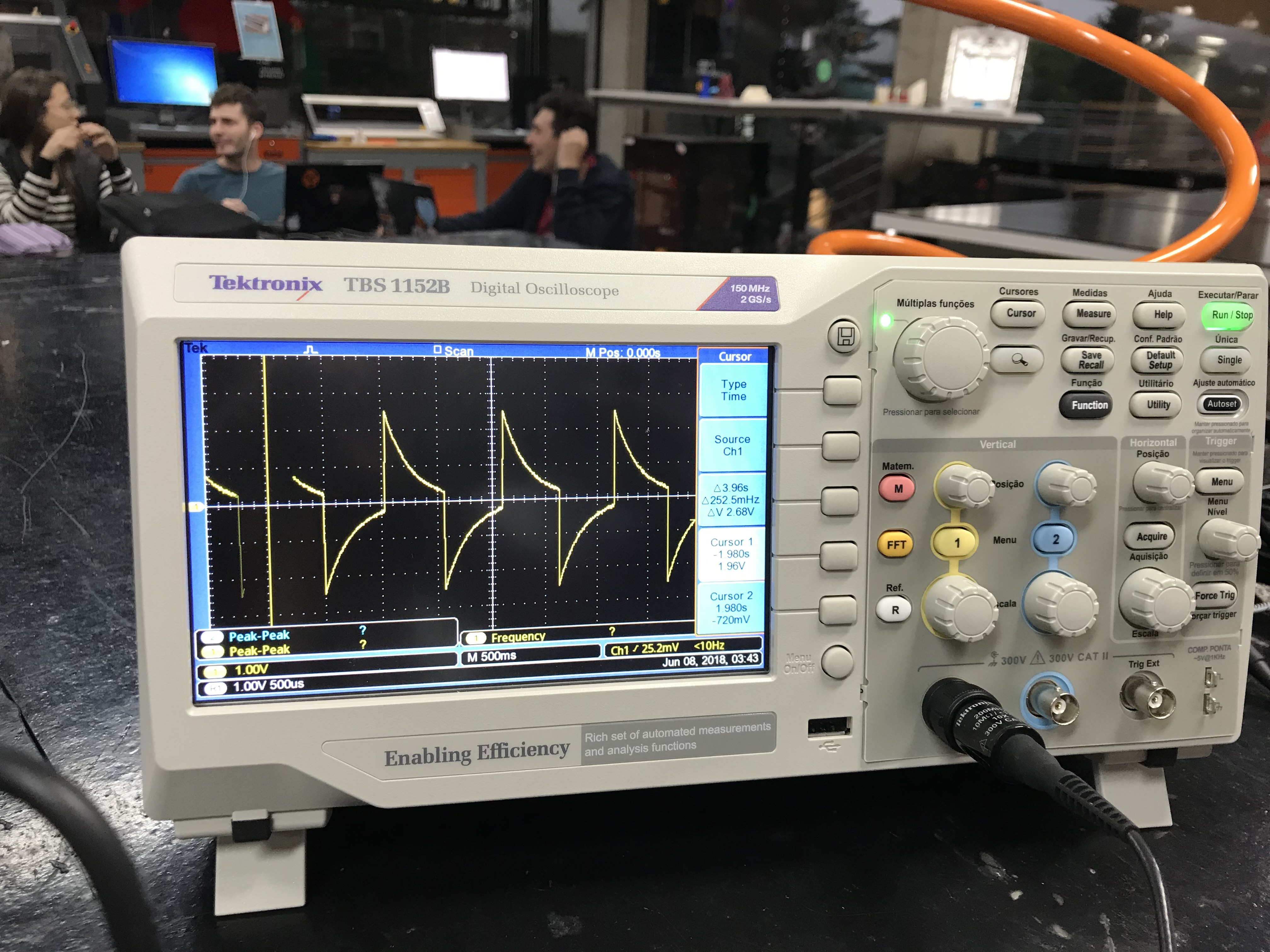
Use the test equipment in your lab to observe the operation of a microcontroller circuit board
The oscilloscope is a device for viewing oscillations, as of electrical voltage or current, by a display on the screen.
Here are two important controls:
Vertical position control: moves the whole displayed trace up and down.
It is used to set the no-input trace exactly on the center line of the
graticule, but also permits offsetting vertically by a limited amount.
With direct coupling, adjustment of this control can compensate for a
limited DC component of an input.
The horizontal position control: moves the display sidewise. It usually
sets the left end of the trace at the left edge of the graticule, but
it can displace the whole trace when desired. This control also moves
the X-Y mode traces sidewise in some instruments, and can compensate
for a limited DC component as for vertical position.
If you want to know more about it click on the
link.
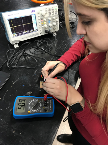
A multimeter is is an
electronic measuring instrument that combines several measurement
functions in one unit. A typical multimeter can measure milliamps (mA)
of current, voltage (V) and resistance (Ω).
If you want to know more about it click on the
link.


