Computer-Controlled Cutting
The assignments for this week were:
- Characterize your laser cutter, making test part(s) that vary cutting settings and dimensions.
- Cut something on the vinyl cutter.
- Design, make, and document a parametric press-fit construction kit, accounting for the laser cutter kerf, which can be assembled
in multiple ways.
Characterize Your Laser Cutter, Making Test Part(s)
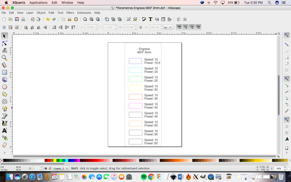
1) The first step is to draw the 2D model using Inkscape.
2) Then you have to save the 2D model in (.dxf) and save it on a pen drive.
3) After that open the model in the CutStudio (the machine software).
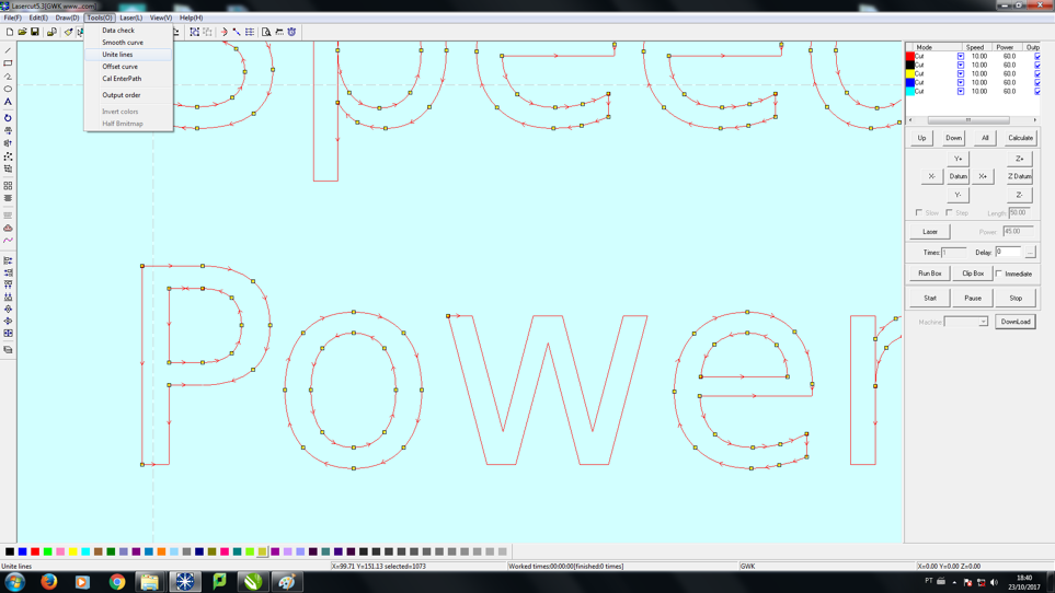
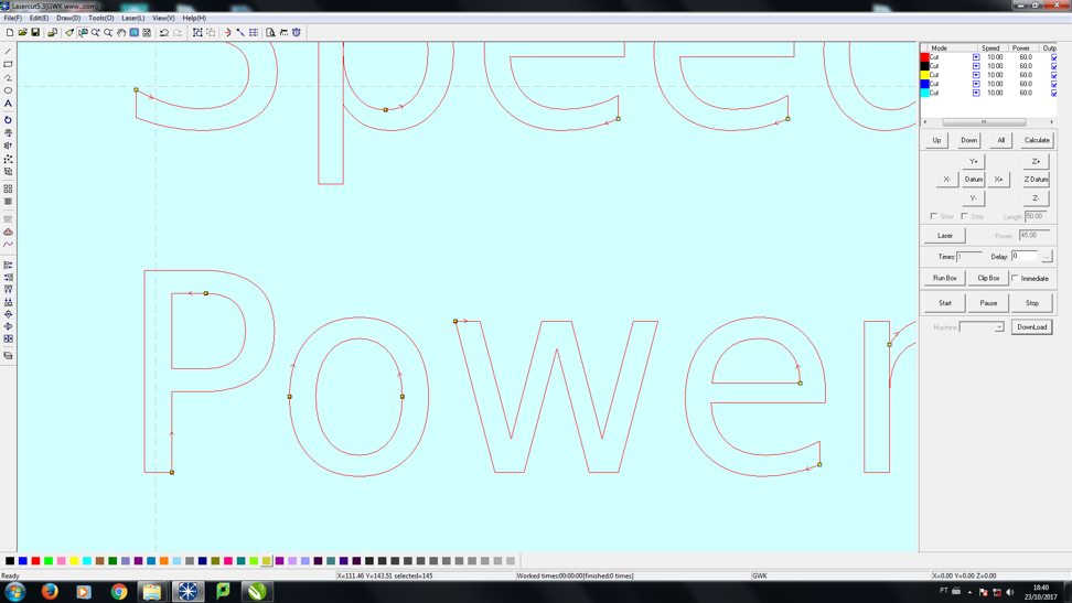
4) Then you need to unite the lines. I did this step by using “Tools(O)> Unite lines”.
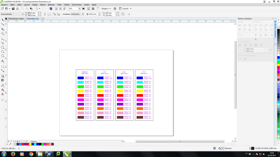
5) Then you need to use the Corel Draw to
realign and change the squares colors. I used the Corel Draw for this
step
because, it was linked to the computer that the machine was hooked up to.
6)
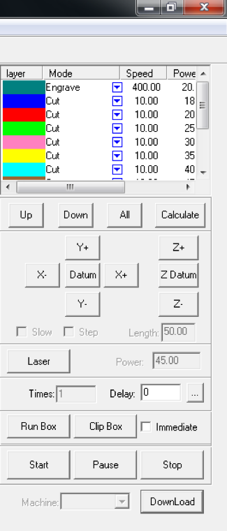
After that you need insert the parameters that you want to test in the
box on the right side. See final image to see
all parameters that were inserted.
7) Once you finished inserting the parameters click on DownLoad.
8) After that you need to turn on the laser
cutter machine. I recommend running a test first to verify the area you
are going to use.
9) Finally cut the 2D model. Video here:
https://youtu.be/KVU-Q8FnXtg .
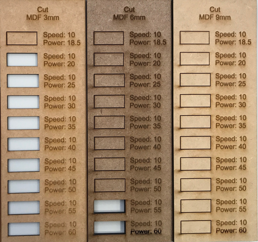
Please take a look at the final image below, you can see that I used MDF material at 3 different thicknesses: 3mm, 6mm and 9mm.
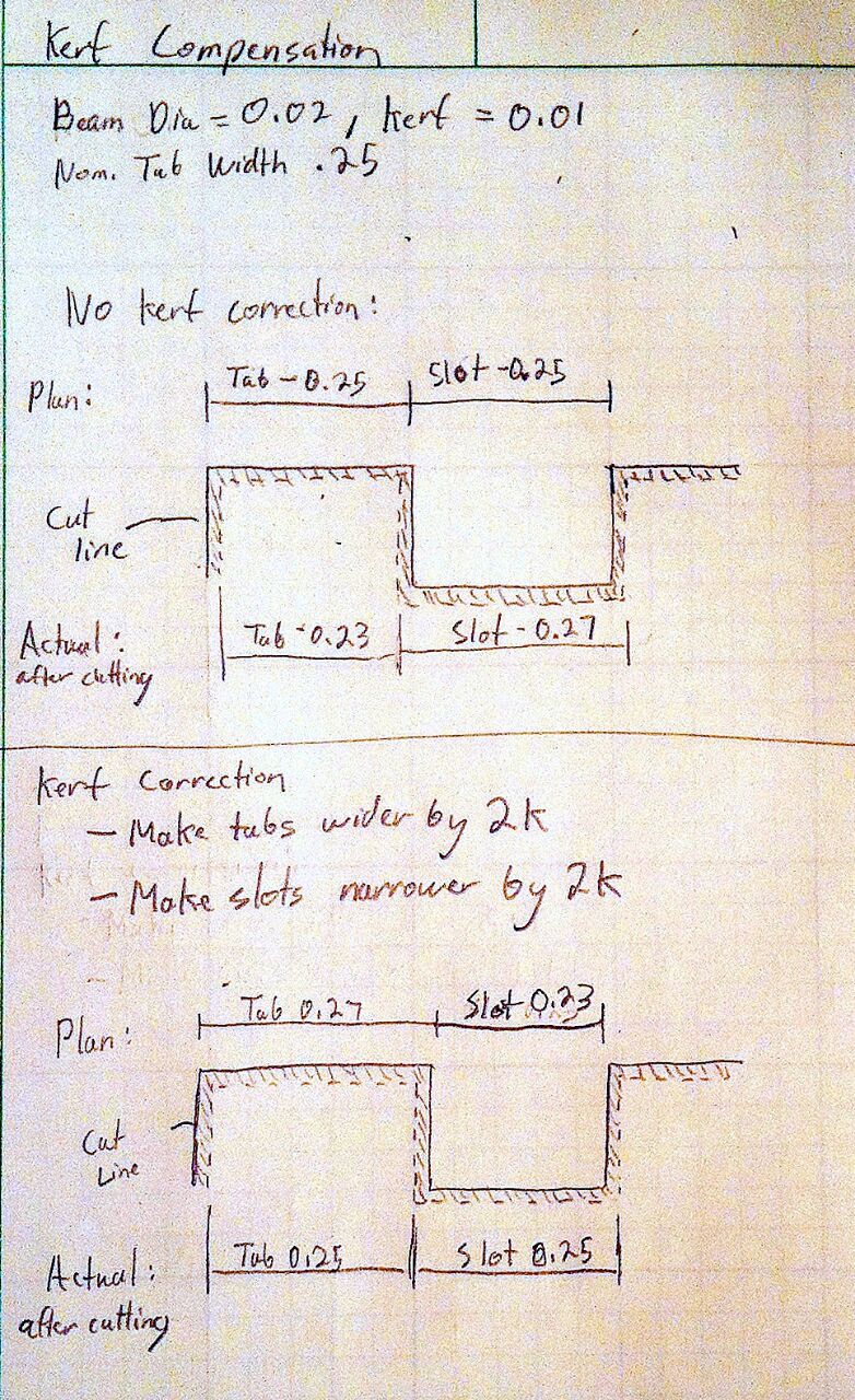
Paulo did the math about Kerf to show the machine parameters
Below there is a demonstration. Also click on the link to his
webpage to see more details.
Kerf:
Kerf=With
Kerf is defined as the width of material that is removed by a cutting process.
When cutting parts with the CNC laser machine
(which is what I used) or any other kinds of CNC cutting machines you
want to produce cut parts with dimensions as close as possible to your
programmed shape. Example if you program a 6" by 6" square and the
laser removes 0.25" of material as it cuts, then the resulting
part is going to be 5.75" by 5.75". So the actual tool path has
to be compensated by half of the tool kerf. In this case it will
be compensated 0.125".
Kerf offset is usually adjusted by who ever is
using the machine. Before running a program, the operator must enter
the kerf width so that the CNC can calculate the actual tool path
required to cut the part to the correct dimensions.
Final comments:
I Learned that the power parameter determines how deep the laser will
go through the material. As you can see in our fab lab we have 3
different thickness of MDF material ranging 3mm-9mm. I chose to use the
same laser cutter speed for all three thicknesses and start the power
of the laser cutter from 18.5-60.
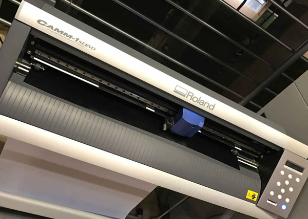
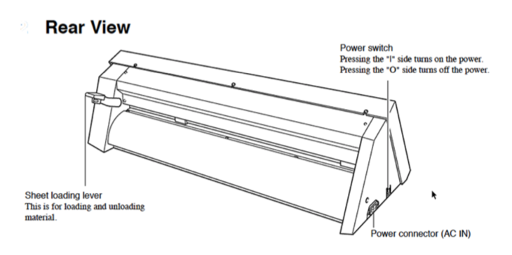
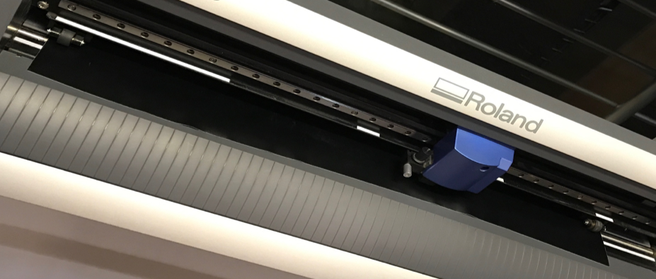
The Vinyl Cutter Machine
The vinyl cutter machine is Roland Camm-1 CX-24.
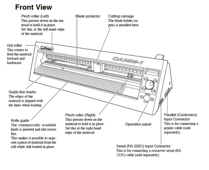
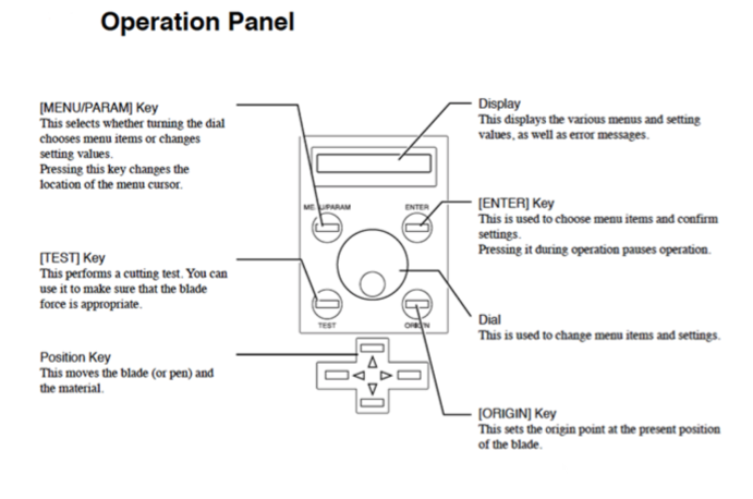
Below are the pictures of the front view, rear view and operation panel of the machine:
File Preparation
The vinyl cutter files must contain only vectors; the vectors must be
lines only, with no fill; the vinyl cutter drivers can only interpret
cut lines. All vectors must be contained within the bounds of the
document canvas.You will need to size your page in your drawing program appropriately for the width of vinyl that you
are using. Vinyl comes in two widths, 24" and 15".You can change
the width and the height using Inkscape. The vinyl is on a roll
so, the max height could be as long as the length of vinyl on the roll.
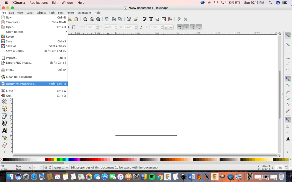
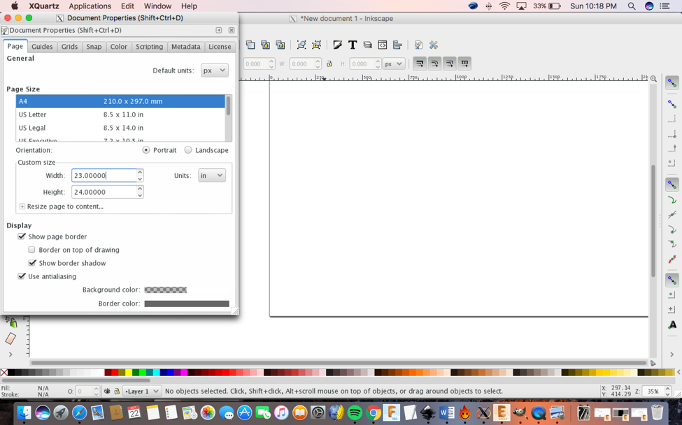
Changing the with and hight using ink skape:
1) File > Document Properties.
2) Modify the width for 23 in and the height for 24 in.
Vinyl Cutter
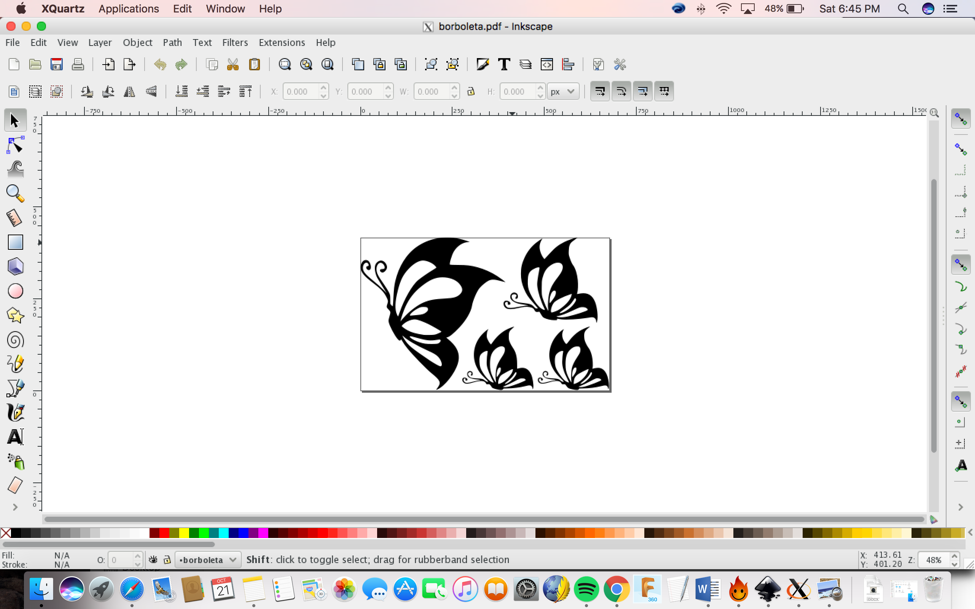
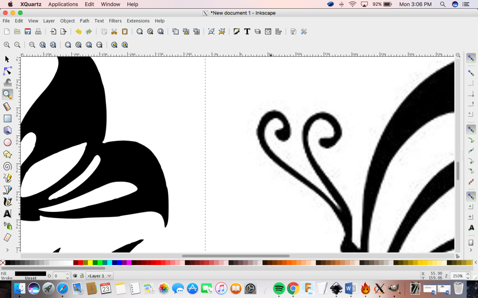
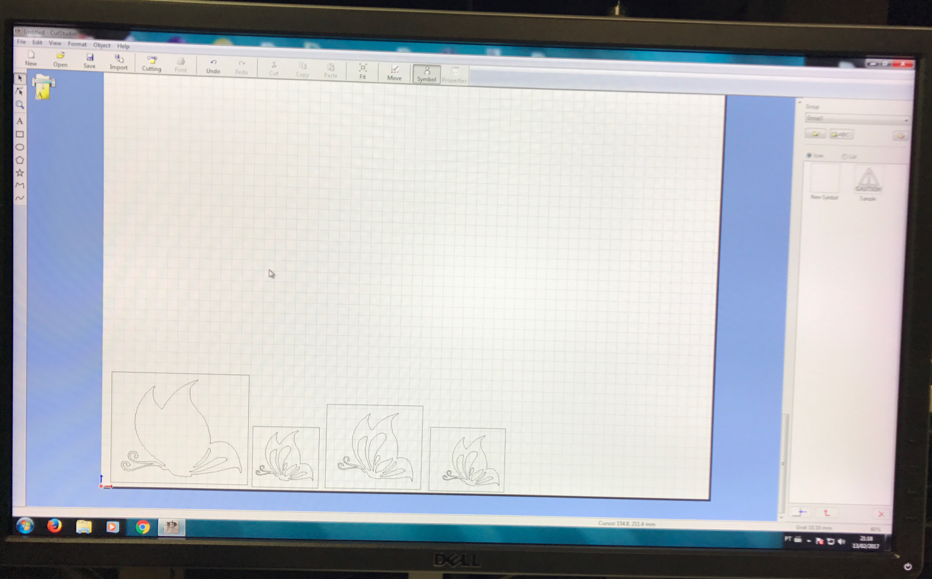
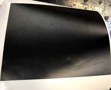
I decided to make four butterflies to stick on my bedroom wall.I used
Inkscape to do it. First I needed to rasterize the JPG image on
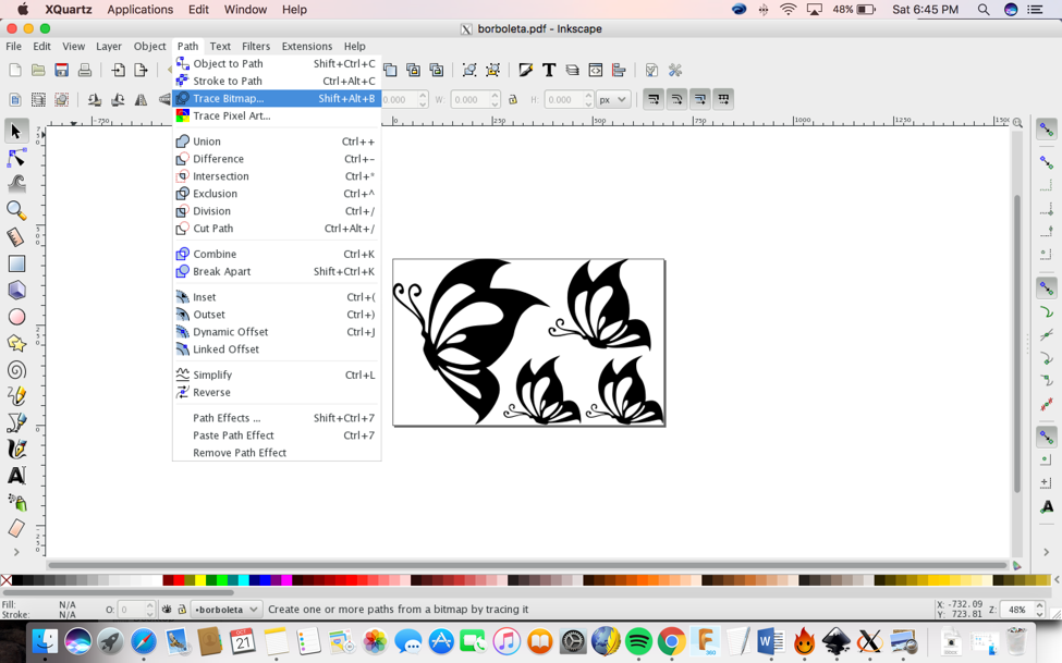
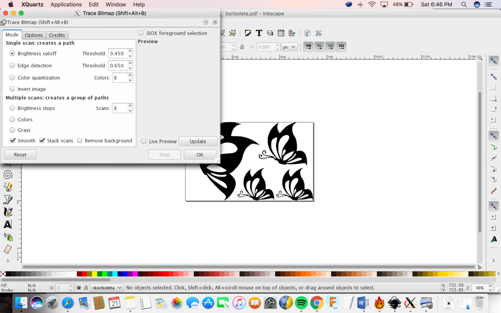
Inkscape by doing:
Path>Trace Bitmap
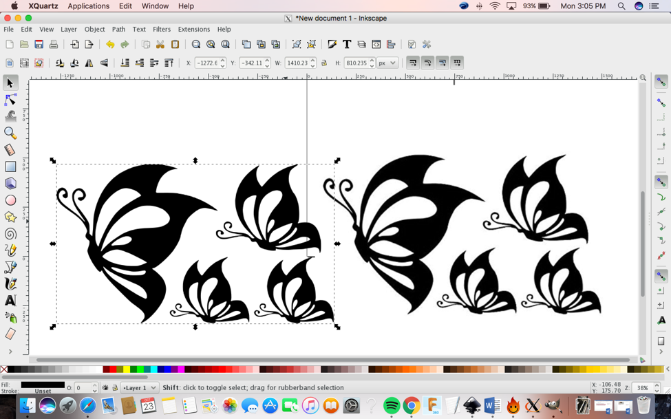
After this process,
I will have a vector above my image, so I can delete the image and keep
just the vector. Then I saved as “.svg” and I realized that I
should save as “.eps” to use the vinyl cutter. I read a tutorial how to
do this whole process using Inkscape.
Click the link:
https://inkscape.org/en/doc/tutorials/tracing/tutorial-tracing.en.html.
Here are the images of my Inkskape during this process:
The next step is to
go to theCutStudio software and choose "File>Print". A window will
open so you need to choose the Vinyl cutter and click as Printer and
then click Print
Now you can load the Vinyl fallow the following steps:
1) Select a roll of vinyl and place it on the rollers behind the machine.
2) On the back right of the machine you will
see a lever; place it in the "down" position so you can load the vinyl.
3) You need to make sure the vinyl side is
facing up as you feed it through the rollers into the vinyl cutter.
4) Under the rubber wheels there is a white sticker indicator.
o Ensure that the vinyl is aligned
properly under the rubber wheels.
o The left wheel must always be
under the wide white sticker on the left.
o The right rubber wheel must be
under any one of the three white stickers on the right, depending on
the width of your vinyl.
o Make sure your vinyl is straight
and about 2-3 inches past the rubber wheels.
5) After inserting the vinyl into the
machine, pull up the lever at the back of the machine to ensure that
the vinyl is securely loaded.
Now you can turn on the Vinyl cutter:
On the left side of
the vinyl cutter is the power button, which you need to turn on. Now
you need to select press “select roll” on the screen.The vinyl cutter
will measure the width of the roll (in
mm).Set the origin by pressing the "Origin" button on the control
panel. After completing this step and material is placed correctly in
the machine, check if it cuts your material properly using the button
"Test". If not, adjust the force and the speed, or check if the blade
is still good to use or if you need to change it. I chose to use a roll
of black vynil material with the force of 100gF and speed of 10 cm/s to
cut my image.
After that you can start to print:
To print the file, go to File > Print > select the "vinyl cuter"
driver from the print menu.Hit the "print" button to send the file to the vinyl cutter.
You can watch a video here:
https://www.youtube.com/watch?v=yRo0vUNnpQ8
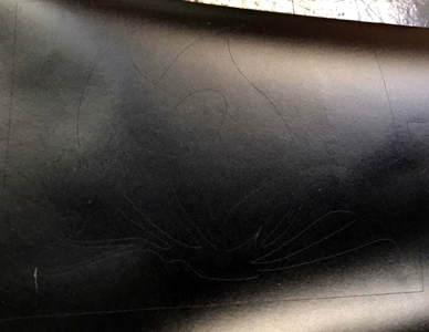
After the vinyl cutter is done you need to cut your file, use scissors
to cut off the section with your cut design, you also need to weed the
vinyl, which is process of removing the unwanted areas from the final
cut design.
The tools I used were:
• Transfer Tape
• Scissors
• X-Acto knife
• Tweezers
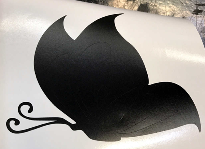
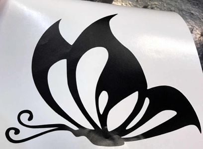
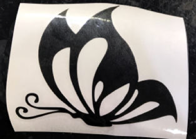
Then after cutting, trim area you want to keep with scissors. After
that remove the unwanted parts of vinyl with an X-Axcto knife and or
tweezers. See the images below:
Once those steps
are finished, you are ready to transfer your vynal image to the desired
surface. Carefully apply transfer tape to the surface of the weeded
vinyl. Rub the transfer tape onto the vinyl to form a strong bond
between the tape and the top surface of the vinyl design. Then after
rubbing, carefully pull the transfer tape (with the vinyl adhering to
it) away from the vinyl paper backing. After you have removed the vinyl
from the paper backing and it is attached to the transfer tape, apply
it to the desired surface. Rub the surface of the transfer tape to
ensure that the vinyl will adhere to the new surface. Then carefully
pull the transfer tape away from the vinyl, leaving the vinyl attached
to the desired surface.
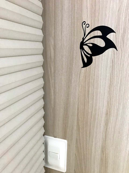
Here below you can see the vinyl butterfly and the butterfly on my closet:
Paramitizing Design and Laser Cutter
Parmaitizing Design:
What does it mean to parametrize (parametric measures) a model?
Use parameters in Design Studies and link them to variables that can be
changed with each iteration of an evaluation or optimization design
scenario. You can parameterize model dimensions, global variables, and
features from Simulation and Motion studies.Link parameters to input
fields to let the parameters drive the numeric value of the associated
feature. For example, if you define Force1 as a force parameter, you
can link it to a force input field instead of entering a numeric force
value. Changing the value of the parameter Force1, automatically
changes the force input linked to it.
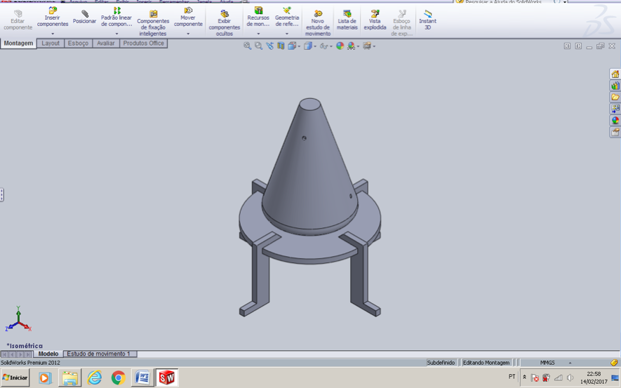
I decided to
designed my Extractor’s support legs using the SolidWorks
software. I came up with this idea when I first designed my Extractor
and then I realized that I should make a support for it because the
solution entrance is on the bottom of the Extractor. The new leg
supporters would not only make my extractor more stable but would also
add more height from the bottom of the Extractor to any surface
allowing more space bellow the solution entrance.
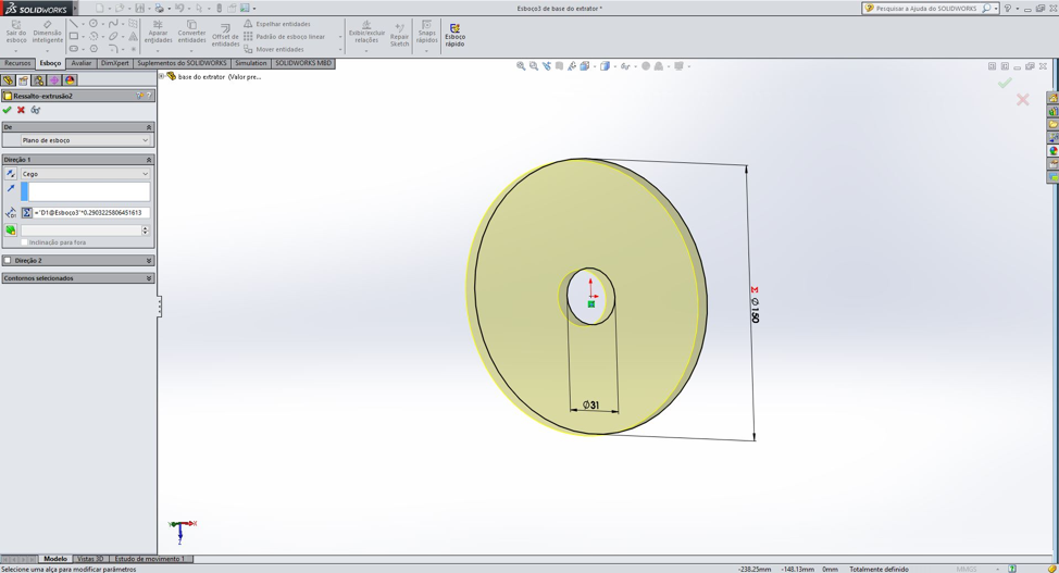
Below is an image from Solid Works of my support design.
Please note
that for this specific assignment I only cut the legs and the support
table. The conical vase was printed at a later date.
The legs:
Below are two pictures of one leg. The first picture is sketched with a
parametric measure and the second is the solid 3D design. When your
parametric measure is complete click File> Save as> Choose the
“.dxf”.
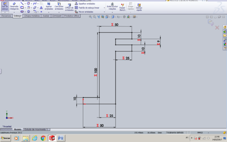
(Sketch with Parametric Measures)
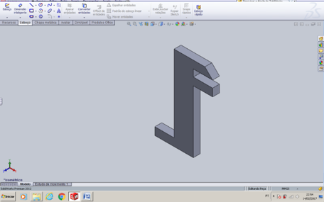
(Solid 3D Design)
Here below is how I
got my leg parametrized. It’s not so hard to do and you can fallow
these steps on how to design an image using a parametric measure
including a picture of my measurements:
1) Insert your sketch
2) Click one of the lines of your sketch and
then you click smart dimension tool at the top left of the window.
3) A small window will appear and Insert the line dimension you prefer in (mm)
4) Create a global variable by clicking the tool next to the red x button
5) Type an = then type in your name for the variable then accept the variable by clicking on the

symbol
6) Click on another sketch line and repeat
steps except for this time insert an equation as you can see in the
image bellow and
click accept.
7) Continue these steps where you see fit to parametrize the dimensions of your sketch.

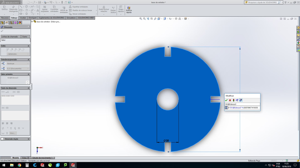
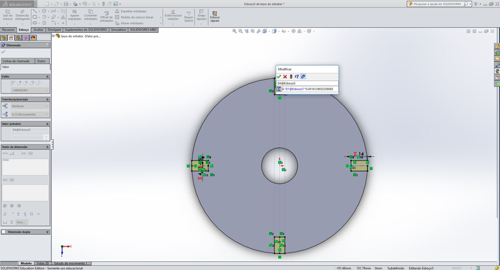
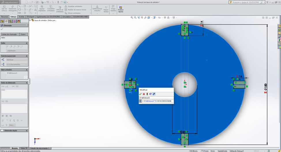
The base:
I used the same concept for the base as I used for the legs. First, I
got the diameter of 31 (the smaller circle, in the center) and I
parametrized all the other measurements starting from this
point.
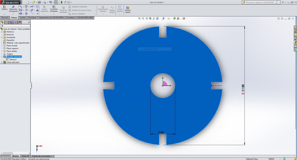
To do this step I used a function (=“D1@Esboço3”*4.8387) which you can see in the image below:
Laser Cutter:
What are Laser cutters?
The laser cutter/s is one of the most useful tools in a modern
fabrication shop or lab. Laser cutters work by directing a very
powerful laser beam, at a precise focal length, onto a material which
they either cut or etch, depending on how the laser cutter has been set
up. Laser cutters cut materials similarly to other computer controlled
tools, only they do it using a beam of light as opposed to a blade.
Once the laser cutters are set up to etch something on the
surface of a material, they operate like a printer, basically using
their laser beam to etch an image onto something.
I first read a tutorial about the laser cutter before using it:
http://www.instructables.com/id/How-to-Use-a-Laser-Cutter/
Below you can see the mane steps on how to use the laser cutter:
1) You first need to have a software
such as Inkscape, CorelDraw, Illustrator to convert you image to a
vector. I used Inkscape.
2) Then you need to choose which
material between Cast Acrylic, Extruded Acrylic; ABS; Polycarbonate;
Anodized Aluminum;
Glass; Wood. I used 9 mm MDF material to cut the legs and base.
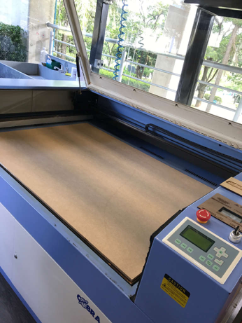
3) After that you need to place your
material inside the machine the dimensions. The machine used is model:
G-WEIKE laser cutter
model LC1390. The machine dimentions are: 130cmx90cm
4) Once everything is placed, you may need to
adjust the bed. There is a focus button on the front control panel of
the Laser Cutter.
If you push that, and
then the down arrow, you should see the bed lower. Keep lowering the
bed until you have enough space that
the laser will not come into contact with your materials.
5) Now that everything is placed, you need to
do a test run. For this step, leave the lid open, otherwise it will not
run the test and may
start to actually cut.
Before the actual cut, you may want to ensure that your print area is
contained within the space you're hoping for.
There is an easy ways to do this:
If you tape over your
print area, or tape a sheet of paper over the area you intend to print
(make sure you cover more than just
the intended
print area, in case your measurements are off, this is what makes a
test cut useful), you can etch into the paper
or tape,and make sure the laser is only going to cut the areas you plan.
6) After you run the test you close the lid.
Go back onto the computer in the File -> Print ---> Preferences
menu, select Raster
or Vector depending on what you
plan to cut. Once that's selected you can, choose the Power and Speed
settings that would
be most suitable for your piece. If
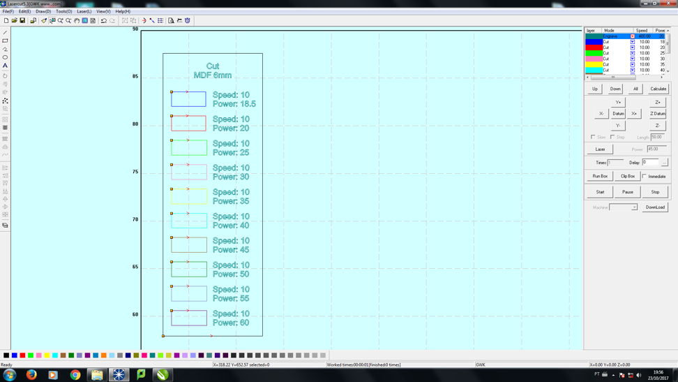
you're cutting in Vector, don't forget the Hertz setting. I used speed
of 10 and the power of 60
as you can see in the
picture below. I got the speed and power using the MDF laser cutter
test at the beginning of the page.
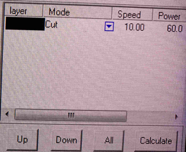
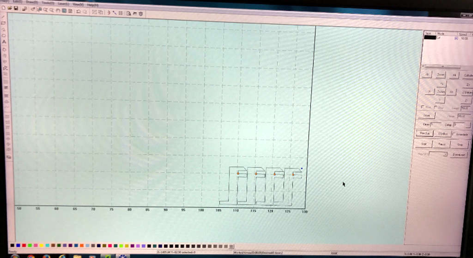
7) Here below you can see the picture of my
design in the Lasercut software. You need to configure the speed and
the power. Once
everything is selected, and properly placed, click OK to start printing from the computer.
8)
If everything looks okay, turn on the exhaust fan. If you're
doing a Vector cut, turn on the air compressor and click GO on the
laser
cutter control panel.
9) After that you will have your cut ready.
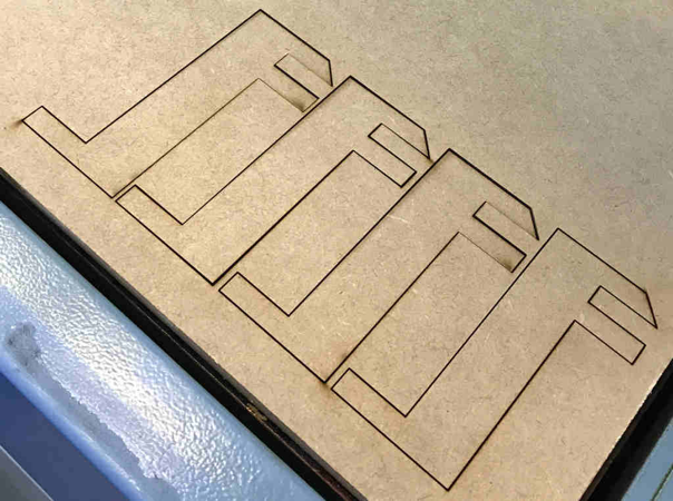
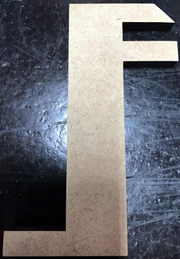
10) Then I used a hand sander for a betterr finish and a
better appearance. My 4 pieces of my extractor support was ready.
(Before Sanding)
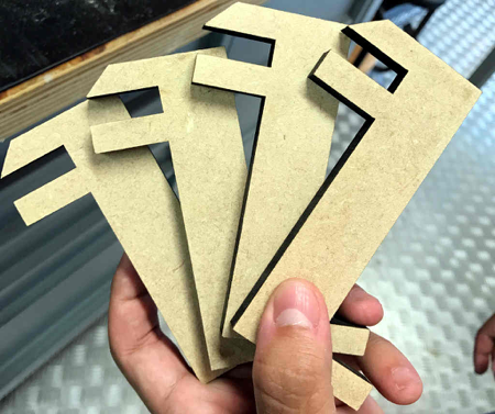
(Finished Legs)
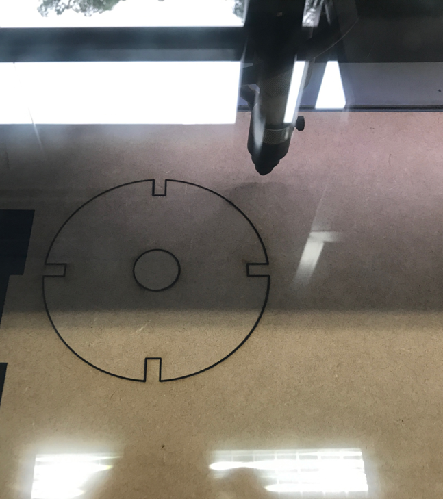
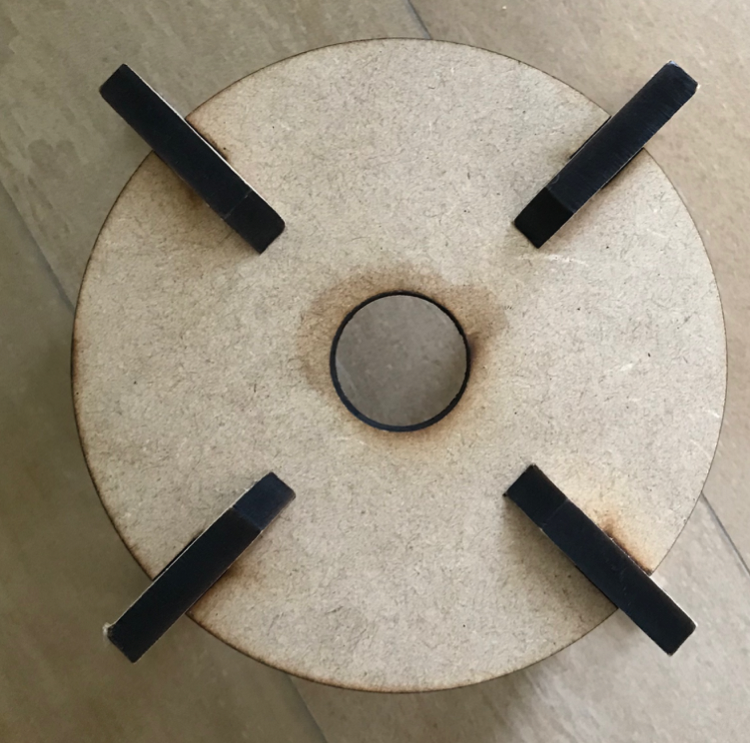
(The base after laser cut)
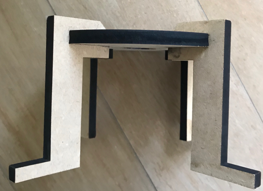
In the pictures below, you can see the base with the legs.


