- To learn abilities like vector, 2D, 3D, render, animate, simulate.
- To build a possible final project using these tools, and post it on our class page.
This week we
focused on how to use several softwares for design and drawing in 2D
and 3D. We also learned how to edit photos using Gimp so, the photos
would not post heavy when we push our web content on to the web
page. It has been a lot of new information for me. I didn't
have a lot of experience with design before this course, just the
basics, which I learned during my first semester of university.
I used a SolidWorks premium 2012 for both 2D and 3D design, which my
uncle had in his computer. I have a Mac Book, so I couldn’t find the
SolidWorks download for Mac. I didn’t know how to use this software, so
my uncle taught me the basics skills so I could get started on my
project.
Inkscape
In computer-controlled cutting week, I used Inkscape for 2D modeling please click on on the
link to learn more about 2D modeling and Inkscape.
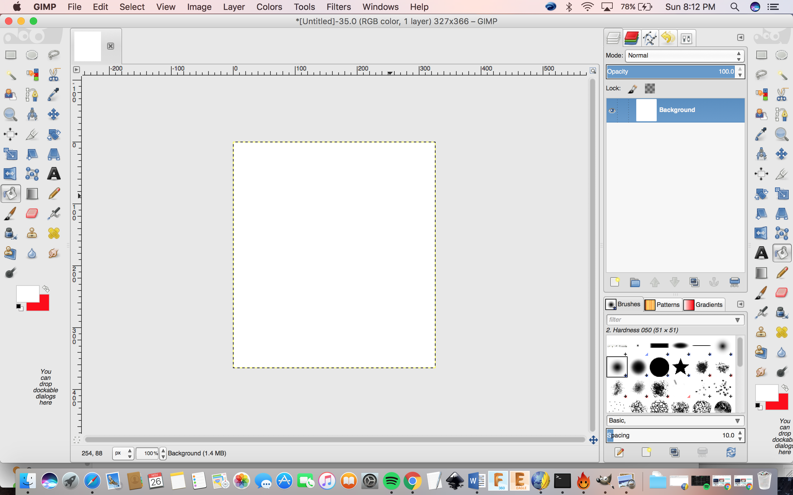
Gimp
I used gimp to edit the photos. In this section I will talk about the basic functions and tools on Gimp.
Download:
https://www.gimp.org/downloads/
Basic Tools:
https://docs.gimp.org/en/gimp-tools.html#gimp-toolbox-introduction
Important functions:
Scale image:
To change the size of the image go to Image> Scale image> then you change the width to 1024> export image..
Highlighting points on image:
Steps:
1. Create a new layer in your image.
2. Select the Ellipse tool from the Gimp Toolbox.
3. Draw an ellipse/circle where
you want it on your image. (Click one spot, drag the mouse to a second
spot, and then release it.)
Recommend
to make it just a bit larger than you think you’ll need it, because the
circle border will have a slight width to it. (Hold down
the Shift
and Alt keys while drawing to make a circle rather than an ellipse.)
4. On the Gimp menu, click the Select menu, then the Border menu item.
5. On the Border Selection dialog
that comes up, select the pixel width for your circle. (I know that’s
not what it says, but that’s
what it
means.) Recommended to use two or three pixels. You can also experiment
with the “Feather Border” setting to see if you like
what it does.
6. When you click OK on that
dialog, you should now see that your ellipse/circle appears to have a
border, with dashed lines making up
the inner and outer border edges.
7. Make sure the foreground color is set to the color you want.
8. Finally, click the Edit menu, and select the “Fill with FG Color” option.
Rasterize a layer:
Rasterization is making an image into a raster image, also known as a
pixel image or bitmap. Rasterization is usually done to vector graphics
or images that have vector components. Vector components can be things
like text objects that haven't yet been rasterized such as letterforms
which are vector images. Rasterization usually reduces the image to one
flat layer, and thus limits the edit ability to a minimum. You will
want to keep a non-rasterized version of your file archived at all
times, just to make adjustments later, if necessary.
Note: I didn’t have a need to rasterize a layer but it is still an important function.
Steps:
1. Start the GIMP application.
Select "File" from the menu at the top and choose "Open." In the dialog
that appears locate and open a
file containing a text layer you want to rasterize.
2. Go to the "Layers" panel and
right click on the text layer. From the options, choose "Discard Text
Information." This does not, as you
might
think form the name, delete you text. Instead, it turns it into a
standard graphic by rasterizing it.
3. Select "File" from the menu and choose "Save."
Animation:
I didn’t have a need for this in my project but I found a tutorial on
how to create an animation because it can be a useful tool in the
future.
Steps:
1. First thing you should do is
select the pictures you want to use for creating your animated GIF
file. For an easier process,
it is
recommending that you copy all of them in a separate folder. It is also
recommended that you rename all the pictures with
incrementing numbers. For each picture use the number corresponding to
the place it will have in your animation.
2. Now open GIMP.
3. In the GNU Image Manipulation
Program (GIMP) main window, open the File menu and select Open. This
action will launch the
Open Image
dialog. Browse to the folder where you stored your pictures. Then,
select the first image you'll use for the animated GIF.
4. Next, you'll need to do the
same thing for all the other pictures that will be a part of your
animated GIF file. In the window displaying
your first
picture, open the File menu. Then, click or tap on Open as Layers.
Browse to the folder where you stored the pictures and
open the
second picture you want to use for the animated GIF file. If you have
more pictures to add to the GIF file, repeat the last
step: open the File
menu, click or tap on Open as Layers and select the next picture in
your sequence.
5. When all the pictures are
added, in order to get a preview of how your animated GIF file will
look, open the Filters menu, go to
Animation,
and click or tap on Playback. To end the preview, simply close the
Animation Playback window.
6. All there is left to do in
order to fully create your own animated GIF file is to save it. Open
File again, and click or tap on Export As...
In the
Export Image window, select the location where you want to save your
GIF file, type a name for it and (very important) make
sure you
specify the.gif extension at its end. Then, click or tap Export. GIMP
will open a new dialog, called Export Image as GIF.
The only
essential thing to do here is to make sure you check the option called
As animation. If you want to, you can also set the
delay used
between the frames of your animation and whether the GIF animation will
loop forever or not. When you've chosen all the
settings that you wanted, click or tap Export.
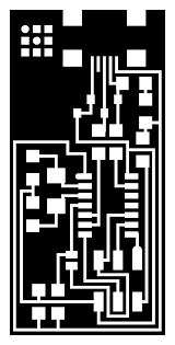
Outline and traces:
My Fab Lab coordinator briefly explained that we will need to know how
to export the outline and traces images of our circuit boards in
monochrome which just means black and white images. This step will be
used during a future weekly assignment. He didn’t go into much detail
as we wouldn’t need this step for this week.
Outline:
Traces:

Sources Used:
https://docs.gimp.org/2.8/en/ (English user manual)
https://alvinalexander.com/gimp/gimp-how-to-create-draw-circle-in-gimp-tutorial
https://www.digitalcitizen.life/how-create-animated-gif-using-your-own-pictures-gimp
Learning 2D and 3D Design
I believe getting a basic understanding to a more advanced
understanding of SolidWorks tools and functions is essential before
getting started because it shortens the time needed to create your
project as there are many tricks to make it easier to design your
project. It is also very useful to practice using solid works, creating
basic shapes and playing around with the different generic tools to see
how they affect your designs. SolidWorks is very advanced software and
with little knowledge can be very hard to use.
Below is a basic guideline on how to use solid works and other links to extensive guides:
Link
1
Link
2
Link
3
Link
4
SolidWorks User Interface Basics:
Click on the link to go into more detail:
http://shoutmetutorials.com/solidworks-user-interface/
Menu bar:
You can find the menu bar at the top most portion of the Solid works
user interface. It contains some standard menu tools (New execution of
files, Open, Save, Print, Select, Undo, Properties, Options and
Rebuild), SolidWorks search, fly out menu help options and detailed
SolidWorks side drag menu.
Command Manager:
The command manager tool bar contains the most frequently used tools
for designing process. It contains various sub-sections such as
“Features, Sketches, Evaluate, DimXpert, Office products”. Each
sub-section is arranged in tabbed manner. So, to access it, just click
on the tab, it will automatically update with available tool services
in the command manager. rom the toolbar dropdown or go to “Tools ->
Customize”.
Features: It
contains 3D solid addition and elimination tools like extrude
boss/base, Revolve Boss/Base, Loft Boss/Base, Sweep Boss/Base, Boundary
Boss/Base, Boundary Cut, Extrude cut, Revolved cut, Sweep cut , Loft
Cut , Boundary Cut, Fillet, Chamfer, Simple Hole, Hole Wizard, Rib,
Shell, Draft, Reference Plane, Linear Pattern , Circular Pattern,
Mirror etc. To see more about SolidWorks Features Tools
Sketch: The
Sketch tools help to make 2D drawing before creation of 3D model. You
can draw any view (Top/Side view) of the product and use the feature
options to add materials. Sketch tools are Line, Circle, Rectangle,
Polygon, Arc, Slot, Ellipse, SmartDimension, Parabola, Sketch Fillet,
Sketch Chamfer, Sketch Trim Entities, Linear Sketch Pattern, Circular
Sketch Pattern , Spline etc.
Evaluate: These tools helps to analyze the design and contains tools like Geometry, Draft, Undercut, Parting line analysis etc.
DimXpert: It is dimension agent of Solid Works, which enables to dimension and tolerance to your modeled part.
Office Products: Other supporting packages like Simulation, Routing, PhotoView360, Circuitworks etc.
FeatureManager Design Tree:
The feature manager design tree helps to see how you construct or
design the model. It shows your sketch 2D files, Feature Tools, planes
etc. From there, you can directly access through each tree function
from the user interface for editing purposes. Overall it gives an
outline about the model development. You can also filter the design
tree by types of feature tools, Sketches, Mates, folders etc.
Configuration Manager:
It manages the different configuration of part or assembly in a design
document. You can select, create and view multiple configurations using
it. Also, you can control the display states of part file by linking
display states to configuration.
Property manager:
The property manager controls the all tools properties of Solid Works.
When you click any tool button on the command manager, the property
manager automatically appears and asks for the value or property entry.
You need to enter or select the correct property values, otherwise it
rejects the entry.
Graphics area:
This is the working area of SolidWorks in which you can draw or create
3D models of different products. It shows the display of parts or
assemblies here. Here you can see a XYZ co-ordinate ate bottom left
corner of graphics area. These trimetric coordinates convert the
graphics area into three dimensions.
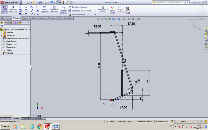
Sketching my project in 2D using solid works:
I needed to make a sketch for my conical oil extractor separating
vessel. My basic understanding of solid works is that it is a good idea
to sketch your model in 2D first and then convert it to a 3D model.
Below I will list the main steps that I used to make a 2D model.
1) I used the referential line in the center to help me to build the shell.
2) I made the shell lines from the bottom to the top, the scale is in mm.
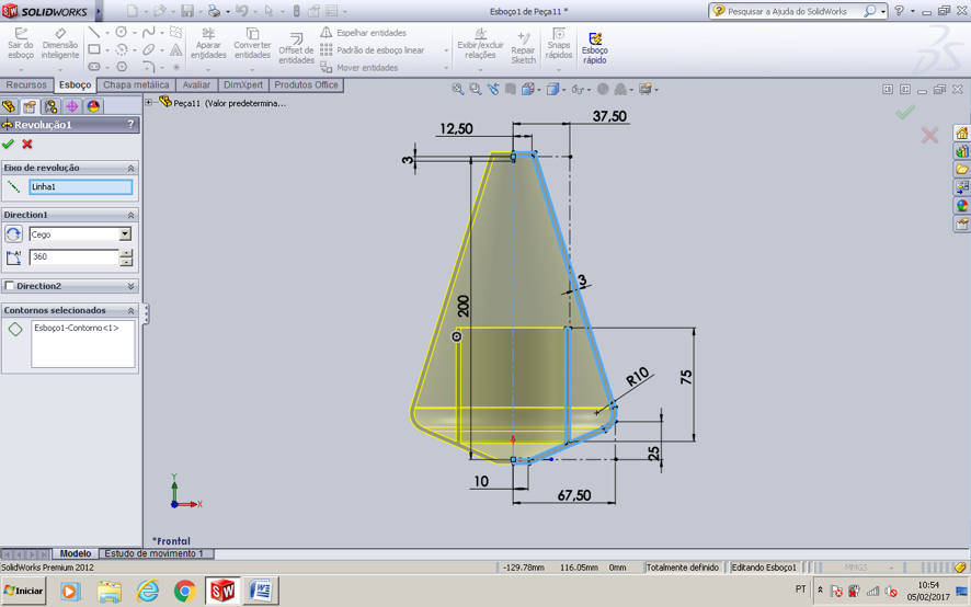
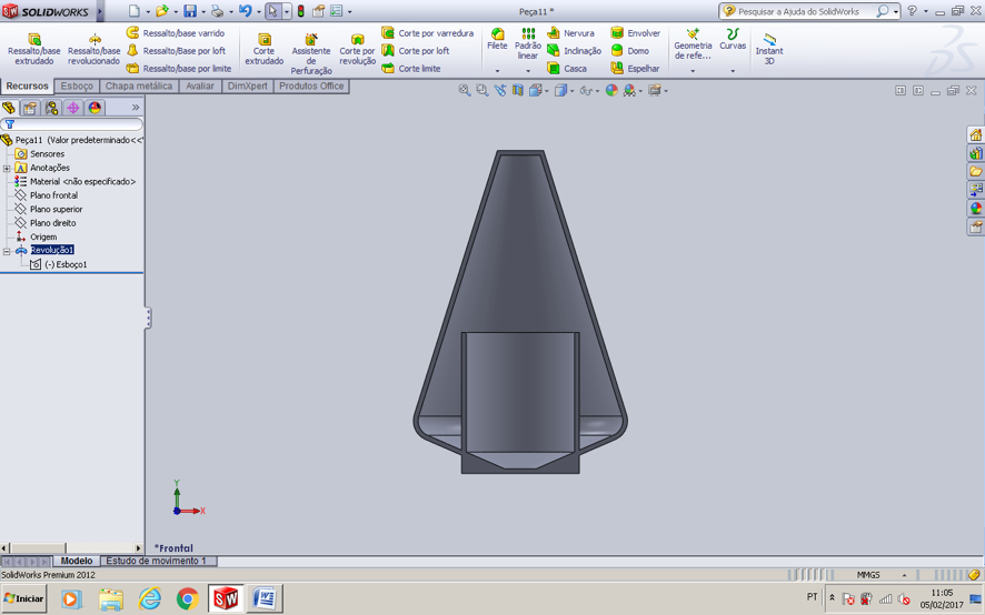
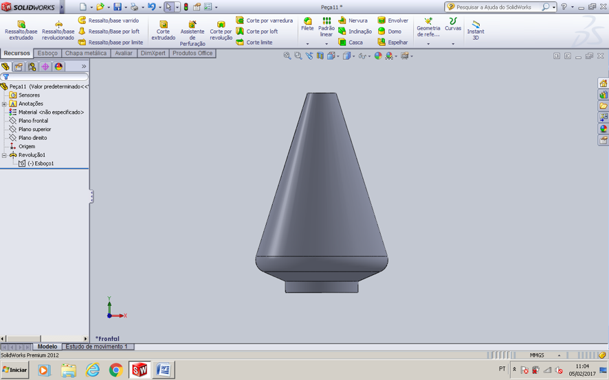
3D design:
I used a revolution tool to build the solid. As you can see, there is a
cylinder in the center of extractor because it will help to separate
the oil from the water. In the picture below I used 180° revolution
only, to visualize better inside. In the next picture, I used the 360 °
revolution.
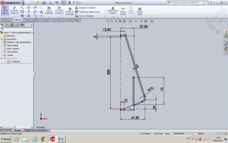
After this step, I realized that I forgot to add a large base to the
bottom to help it with stability when it will be printed on the 3D
printer. So, I went back to my first sketch and added the large base.
You can see both designs below side by side: The one on the left is the
original design and the one on be right is the new design.
In the next picture below I used 180° revolution only, to visualize the
inside of my conical. Now, I can see that the base is much more stable
than the first model.
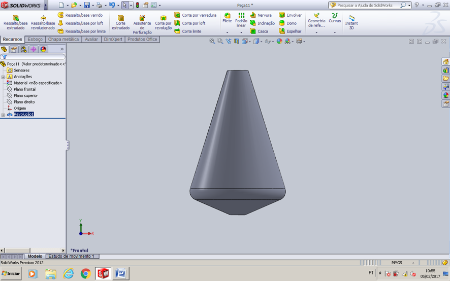
I then used the 360 ° revolution. There is one entrance for the
distilling on the bottom, and two exits, one for the water and the
other one for the oil, on the top. I will figure out the diameter and
better positioning later.
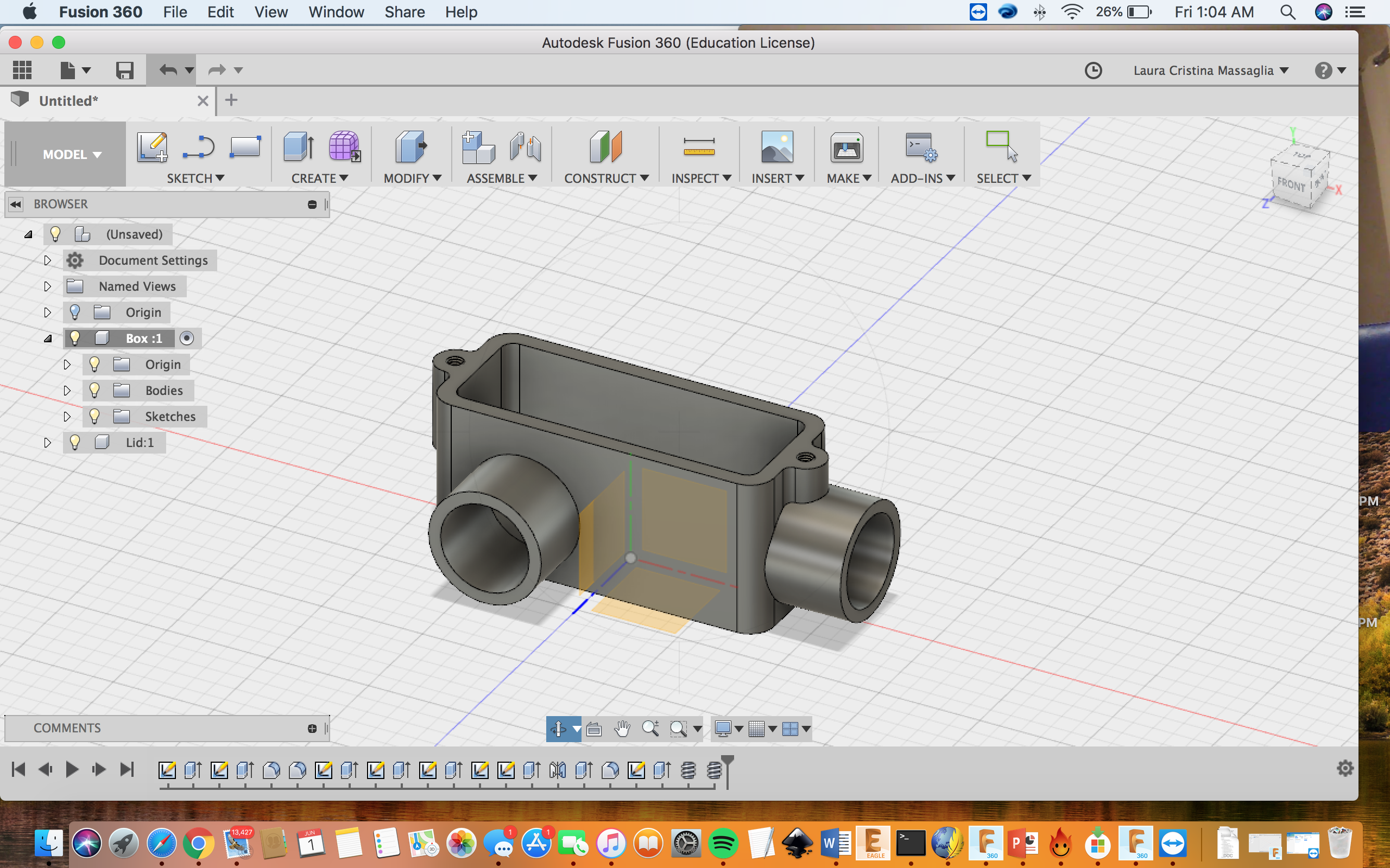
Fusion 360:
Fusion 360 is a cloud-based CAD/CAM/CAE tool for collaborative product
development. It combines fast and easy organic modeling with precise
solid modeling, allowing you to make your designs manufacturable. I
didnt use this software for my project but, I did play around with it
and reaserched how to use it. Here are some links to help you with this
software.
Link
1
Link
2
Link
3
Link
4
I watched the video in link 4 and fallowed the step by step process on
how to build a plastic conduit. Here is the example image of the work I
did.
Final thoughts:
I found Solidworks to be a
very powerful tool in designing, creating,
and building a product. It has many functions and tools that really
help the creator maximize his or her vision. I look forward to continue
to use Solidworks throughout this project and improve my skills. I am
still just a novice at using Solidworks but it has a really good
interface that guides you through your project and makes it easier for
beginners to use. It also was very time consuming if you don’t know
what all the tools and tricks can do. I also found that fusion 360 was
more advanced and harder to use then Solidworks. I had a lot of
difficulty using this software and will need more time to practice. I
look forward to fully learning Fusion 360 in the future.
Project Files:
• Conical.stl
• Conduit.stl
• Plastic conduit
• Conical (Solidworks)
• Plastic conduit (Fusion 360)


