 ASSIGNMENTS
Interface and Application Programming
This week's assignment was:
- Write an application that interfaces with an input
and/or output device that you made, comparing as many tool options as
possible.
First I decided to
make a program/app that I will use in my final project. It will be
linked to the device that I made “input” from a previous week.
The program is a temperature sensor that will measure the water
temperate after the distillation in the extractor. The program that I
used is App Inventor. I did not know anything about App Inventor,
so a Fablab technician taught me the basic tools.
I tried to make an android interface to interact with the input device. I have chosen the mobile platform due to its wide spread use.
I intend to use a Bluetooth module for this assignment to speak to the
board and the phone. Since I have an IPhone, I used the Fablab technician phone,
which is Android to run the App.
The input board:
Please go to this assignment for more details.
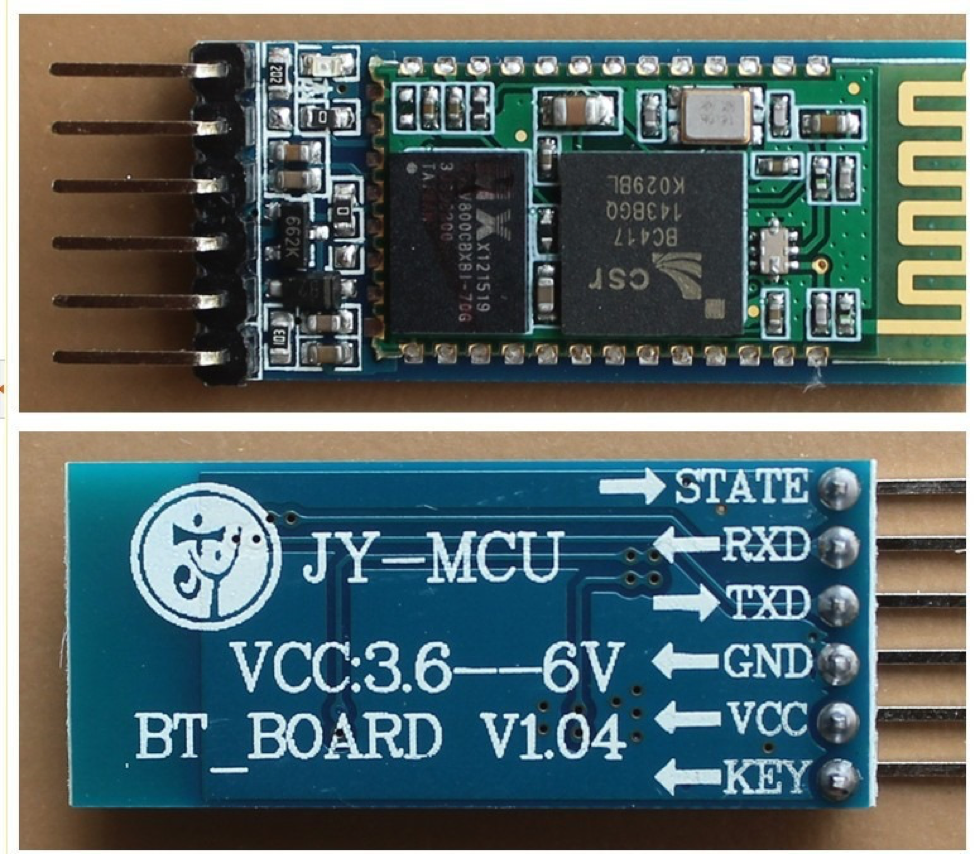
HC-05 module is an easy to use Bluetooth SPP (Serial Port Protocol)
module, designed for transparent wireless serial connection setup.
There is lot of information regarding the pinouts and usage on the
internet. A few useful links are itead.cc/HC-05 and developer.mbed.
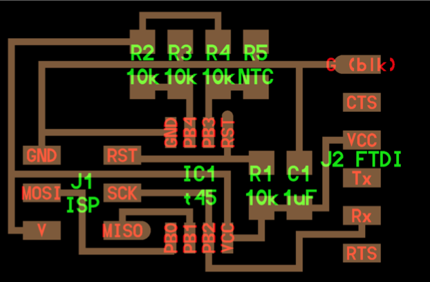
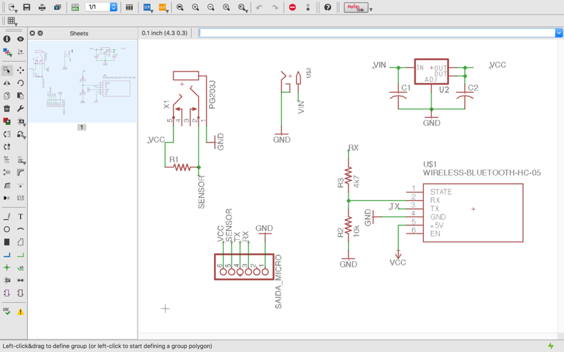
I designed
a new board to pair with a Bluetooth device that would allow the
readings of the thermometer to be received by the app.
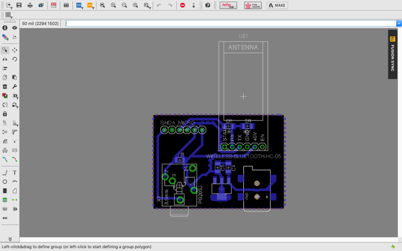
Here below you can see the schematic and the board:
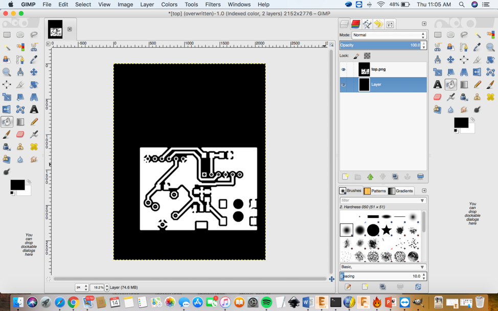
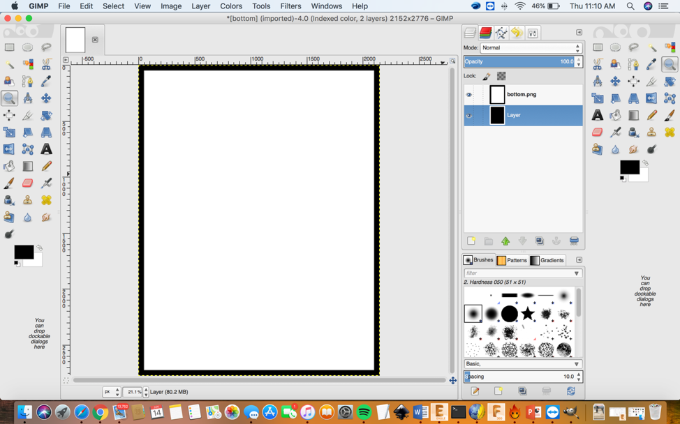
After I finished designing my board, I needed to use the Gimp program to convert the file to a .png file.
The first step before you use the Gimp program is to save the board and the traces.
In the input device week I explained step by step on how you have to
save the file after you design it on Eagle and how you use gimp.
Refresh your knowledge of this process by clicking on this link.
Using Gimp, I generated the interior and exterior of my board as shown in the images below:
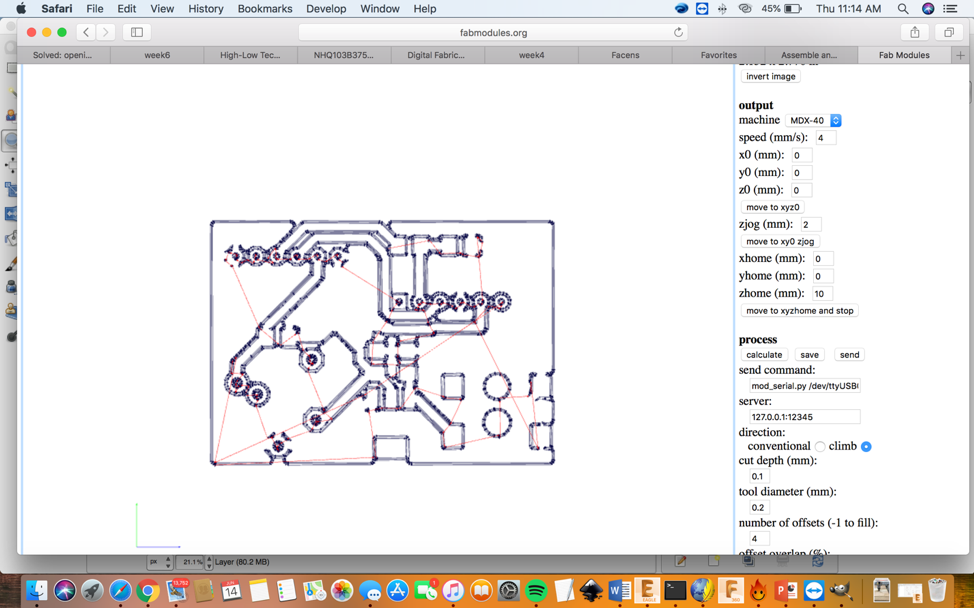
After the Gimp process, you need to go to Fabmodules.
Fabmodules will allow me to program the image so I can cut the board using the Roland mill.
Once, I finished converting the file images I then opened the file on this website: http://fabmodules.org
I also explained a step by step process on how to use Fabmodules during
the “Input Device” week. Refresh your knowledge of this process by
clicking on this link.
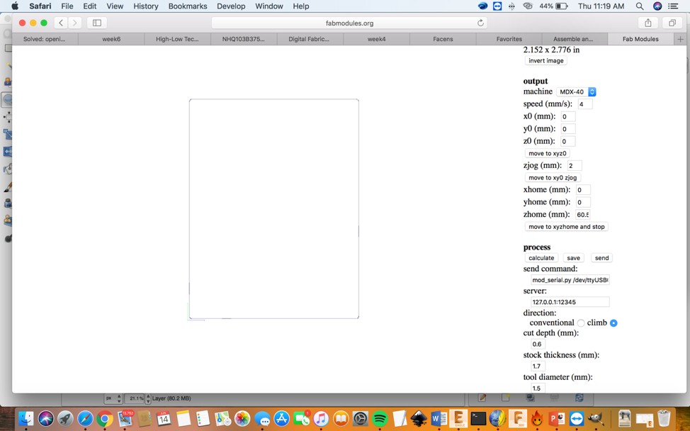
Below are the images on the interior and exterior traces:
For the interior I used a tool diameter of 0.2mm
For the exterior I used a tool diameter of 1.5mm
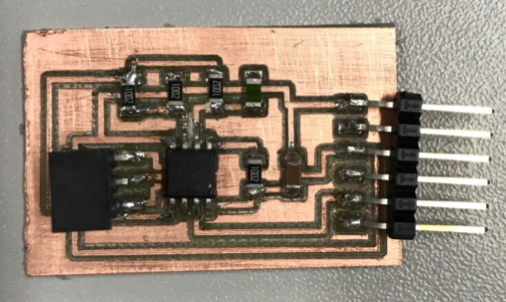
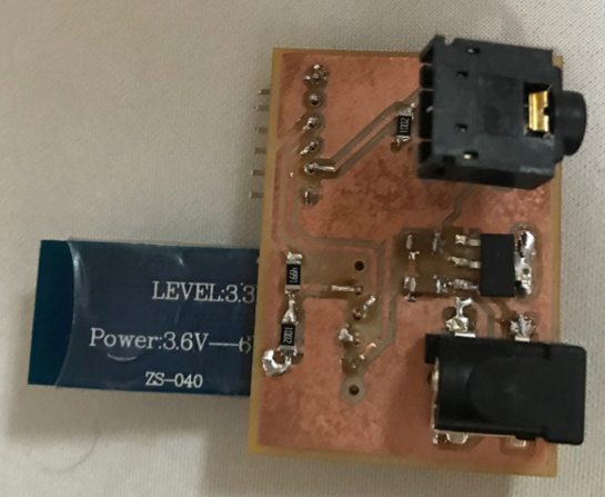
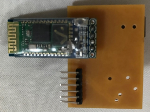
After, I generated the code on Fabmodules the next step was to cut the board and drilled the holes.
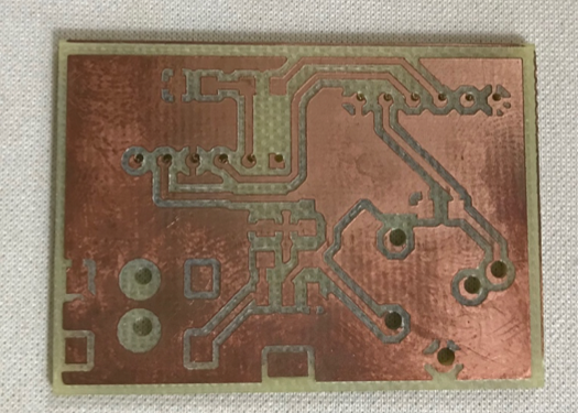
Then I soldered the components as you can see in the images below:
1 x Bluetooth HC-05
1 x Power connector
1 x Audio connector (for the temperature sensor)
1 x 5V voltage regulator
2 x capacitors
2 x 10 kΩ resistors
1 x 5 kΩ resistors
Once the board was soldered it was time to programed it.
To program this board, I used the input board from the previous week. I
first wrote the code using the Arduino software. Then the next step is
to connect the boards to the computer which I explain more further down
the page. The code only does these two things, reads the sensor and
sends via Bluetooth
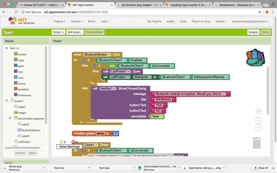
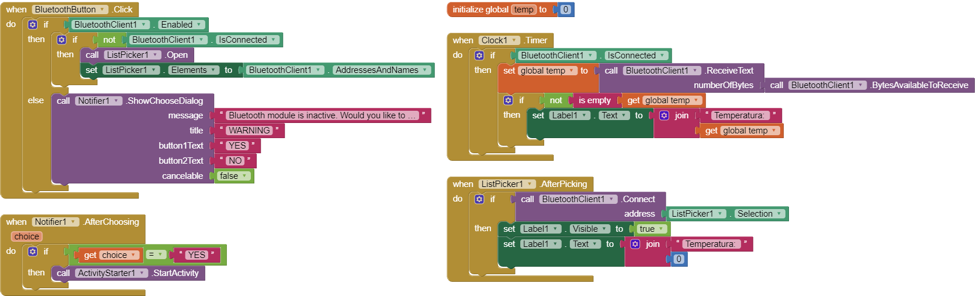
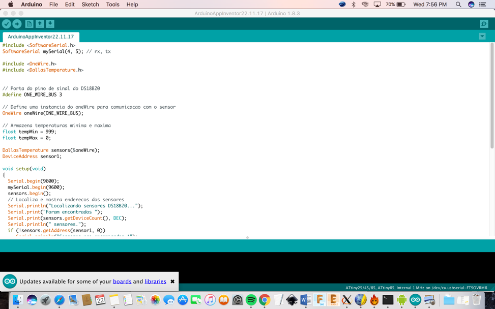
Here is an image of the program:
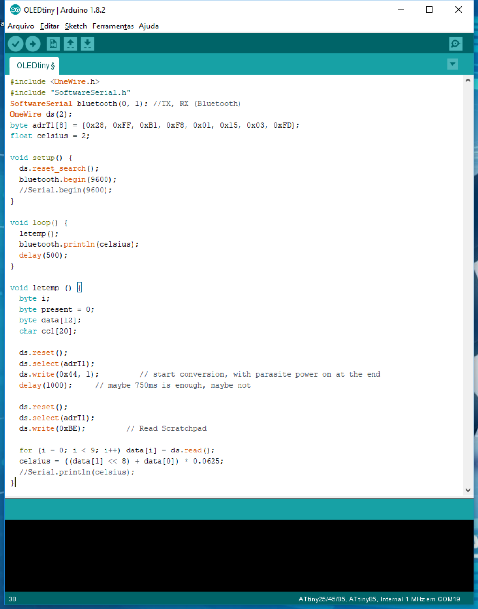
At the top we have the libraries, the definition of two Bluetooth ports
and the sensor port. In the Setup we will initialize the sensor and
Bluetooth.
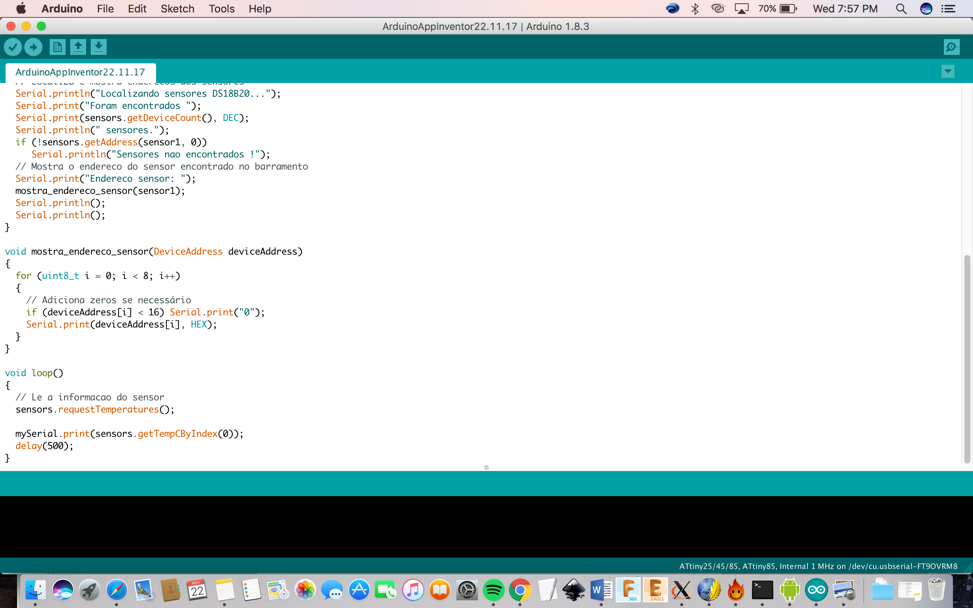
Just below it is the Loop, there the code keeps repeating itself, the
sensor is read and sends it by Bluetooth. I created a function to read
the sensors to find out where the connections need to be made. How this
step is done is to first search for the sensor address, then send
a request and read the bits that the sensor sent.
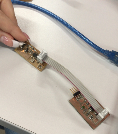
After programming, I connected my input board to the FabISP board which
is connected to the computer. I then programmed the input board with
the code as I explained above. Bellow is the image of the connected
boards:
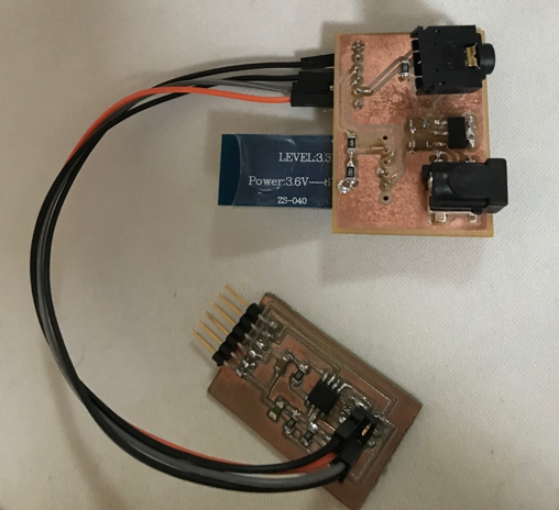
Then I connected the input board to the Bluetooth board I made in this assignment.
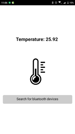
In this video you can see that the bluetooth is working with the temperature sensor.
MIT Appinventor:
Below you can understand better how to use the App Inventor:
1) The first step is to have an gmail account.
2) Then you can start the project by clicking on “New Project” in the right side of the page.
Then you name your project, mine I named as “Test1”.
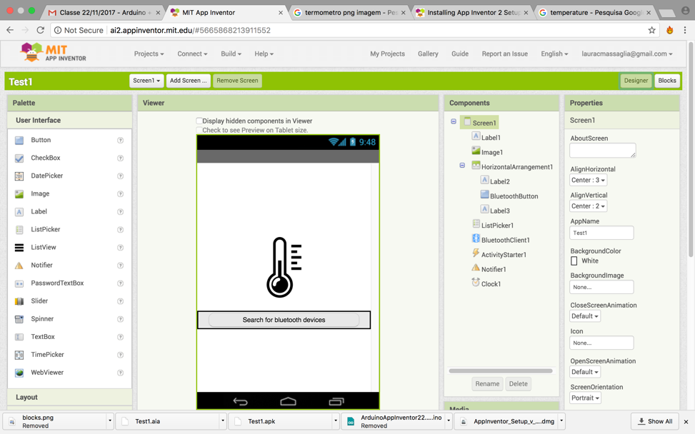
3) After that you can start the design. The Design
Window, or simply "Designer" is where you lay out the look and feel of
your app, and specify what functionalities it should have. You choose
things for the user interface things like Buttons, Images, and Text
boxes, and functionalities like Text-to-Speech, Sensors, and GPS.
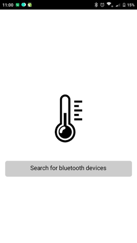
4) Then you will add a button. Our project needs a
button. Click and hold on the word "Button" in the palette. Drag your
mouse over to the Viewer. Drop the button and a new button will appear
on the Viewer. In my project I named the button as “Search for a
Bluetooth device”.
5) After that you connect the app inventor to your
phone for live testing. One of the neatest things about App Inventor is
that you can see and test your app while you're building it, on a
connected device. If you have an Android phone or tablet, follow the
steps below. If you do not have a device, then follow the instructions
for setting up the on-screen emulator (opens a new page) and then come
back to this tutorial once you've gotten the emulator connected to App
Inventor.
6) Then you need to get the MIT AI2 Companion from the Play Store and install it on your phone.
7) Now you need to start the AICompanion on your
device. On your phone, click the icon for the MIT AI Companion to start
the app. NOTE: Your phone and computer must both be on the same
wireless network. Make sure your phone's wifi is on and that you are
connected to the local wireless network. If you cannot connect over
wifi, go to the Setup Instructions on the App Inventor Website to find
out how to connect with a USB cable.
8) After that you need to Get the connection code
from the App Inventor and scan or type it into our Companion App.
On the Connect menu, choose "AI Companion". You can connect by:
Scanning the QR code by clicking "Scan QR code" (#1); or Typing the
code into the text window and click "Connect with code" (#2).
9) After that you will see your app on the connect device.
The Initial testing using Arduino:
I programmed the board by using Arduino.
First I needed to download the Dallas Temperature at the Arduino
library by clicking: Sketch > Include library>
DallasTemperature.
Then the Guru helped me to program the board since I don’t have a lot of experience.
We worked together for a while figuring out the correct code for my specific project.
Below you can see the screen shots of my coding:
Video:
If you have any troubled understaniding how to do these steps here is another tutorial:
http://archive.fabacademy.org/archives/2017/fablabtrivandrum/students/312/exercise16.html
Project Files:
• Arduino code
• App Inventor
• App
• Temperature sensor
• Board schematic
• Board
• Outside (.rml)
• Inside (.rml)
|

