Input Devices
The assignment for this week was:
- Measure something and add a sensor to a microcontroller board that you have designed and read it.
- Measure the analog levels and digital signals in an input device.
Designing and Configuring My Board
I initially decided to work with RTC thermistor as my input device,
because for my final project I would like to measure the oil
temperature by the end of the process. I decided in the end to to use
the NTC thermistor.
First I read about the RTC thermistor using the document link provided by FAB course:
https://www.digikey.com/product-detail/en/PTS120601B1K00P100/PTS12061.0KCT-ND
I also read about the NTC thermistor in this document link:
https://www.digikey.com/product-detail/en/NHQ103B375T10/235-1109-1-ND
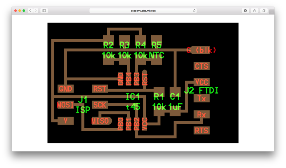
I used the hello.temp.45 provided by the course to design my board:
http://academy.cba.mit.edu/classes/input_devices/temp/hello.temp.45.png)
Eagle:
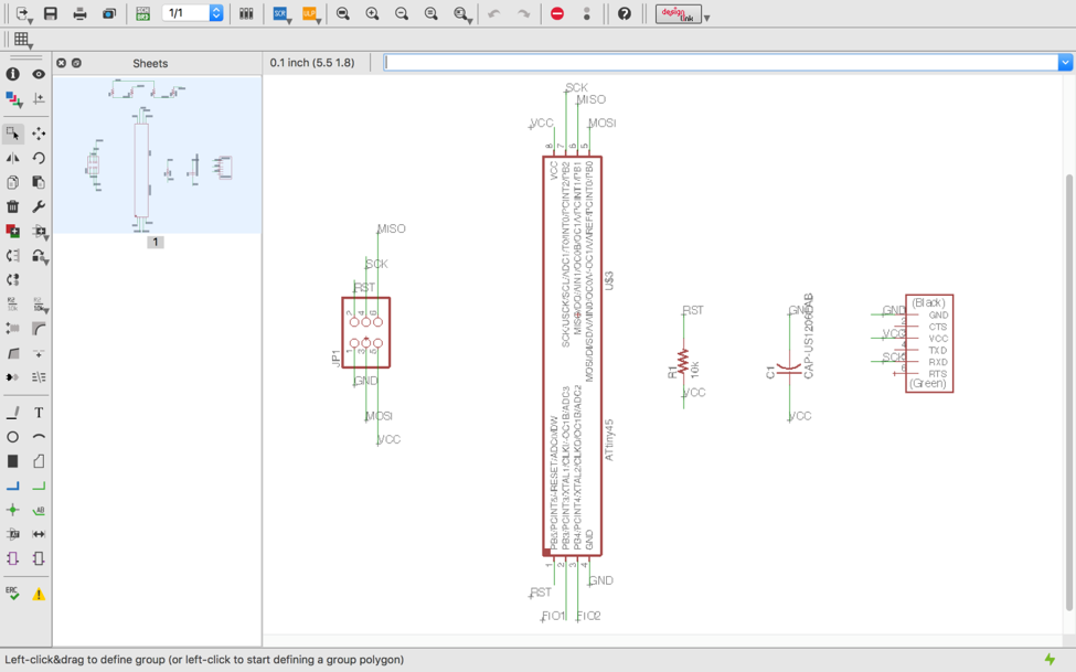
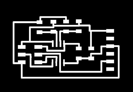
Then I started to draw on the Eagle program as you can see in the image below:
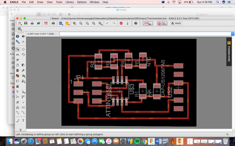
I switched to board and I connect the components as you can see in the
image below. I tried to figure out the best way to make a small board.
After I finished
designing my board I needed to use the Gimp program to convert the file
to a .png file. Before I used the Gimp program I needed to save the
board and the traces.
Here are the following steps I took using the Eagle still to save the board and traces:
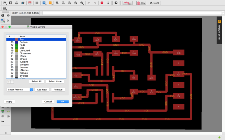
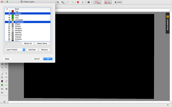
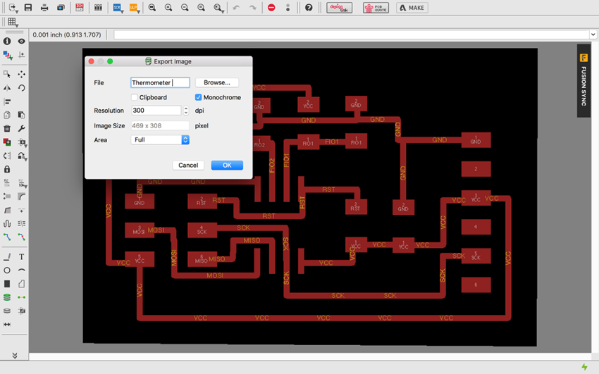
First I went to layer settings, selected none and then I selected only
the top layer. After I selected the top image I went to file >
export > as image > then I chose the file. I selected the
monochrome and then clicked save. Then I selected only the bottom and
dimension. After that I went to file>export>as image>then I
chose the file. I selected the monochrome, then I changed the dpi to
300 from 500 and then clicked save.
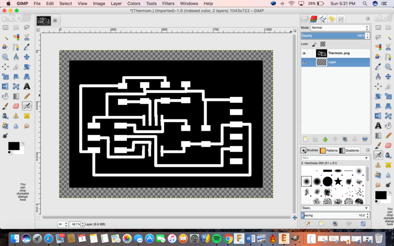
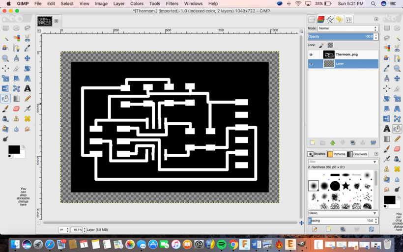
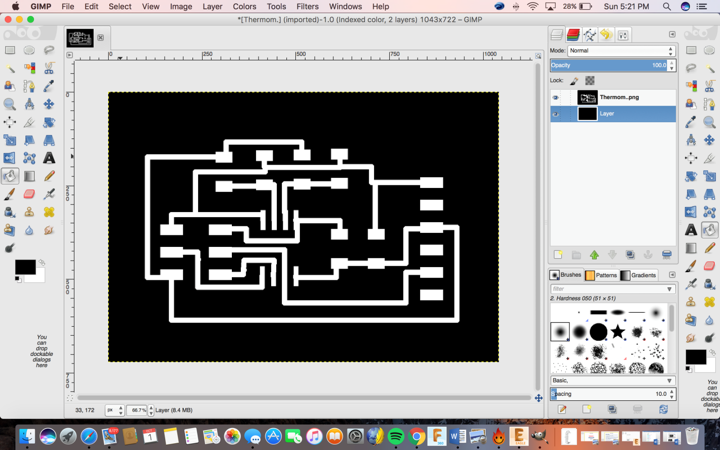
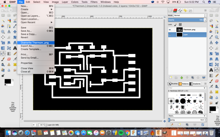
Gimp:
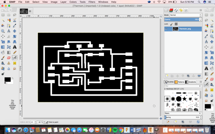
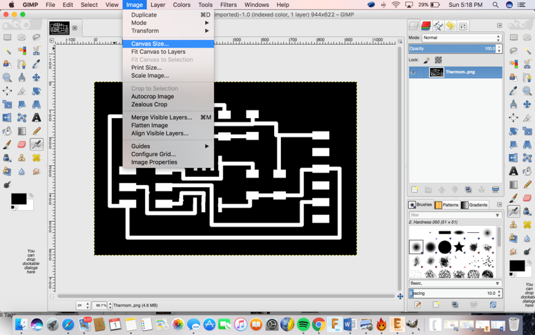
Using Gimp I generated the interior and exterior of my board.
The interior:
1. I first opened the file that I exported from Eagle.
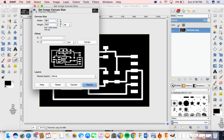
2. Then I clicked on Image>Canvas Size..
3. I then needed to add 100 pixels to
the width and height. I changed the width from 944 to 1044 and the
height from 622 to 722 and Then I
centered the image and finally I clicked on resize.
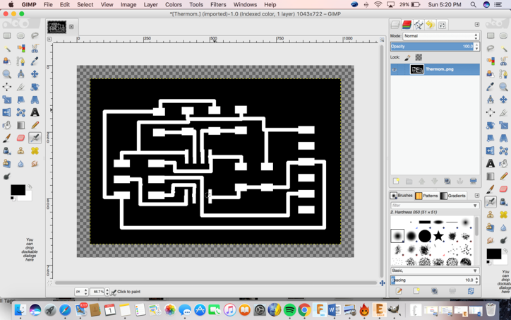
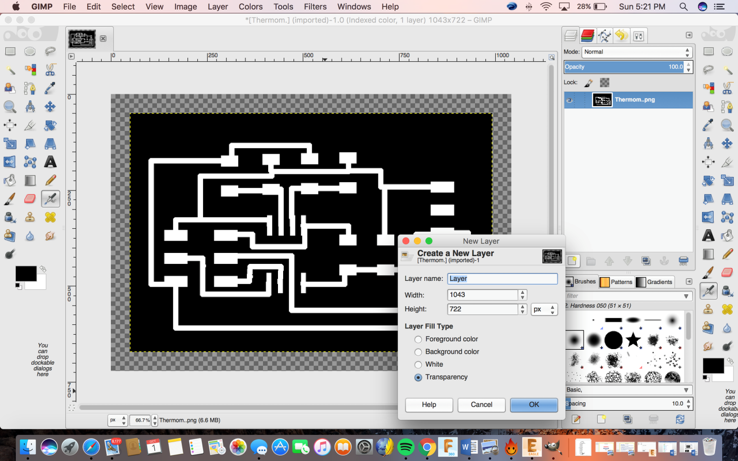
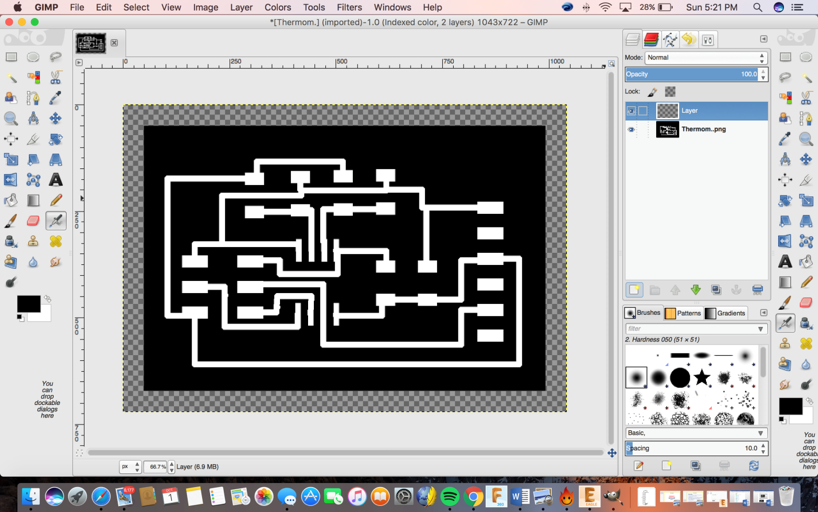
4. I then needed to create a new layer
5. After that I put the layer highlighted in blue below the original layer. Then I need to make the checkered grey layer all
black by selecting
the bucket fill tool and selecting the color black. Once I completed
that step I clicked on Overwrite
the file. After I had overwritten the file I opened the new file. Fallow the image sequence below to see these steps.
Outline:
I repeated these same steps on gimp for the outline. Final result below.
Fabmodules:
Fabmodules will allow me to program the image so I can cut the board using the Roland mill.
Once I had the finished converting the file images I opened the file in this website:
http://fabmodules.org
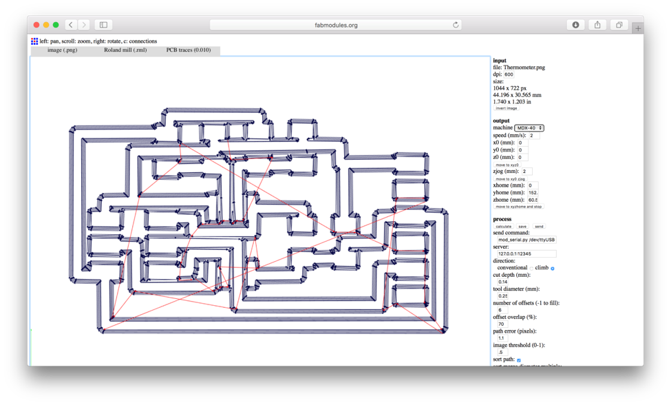
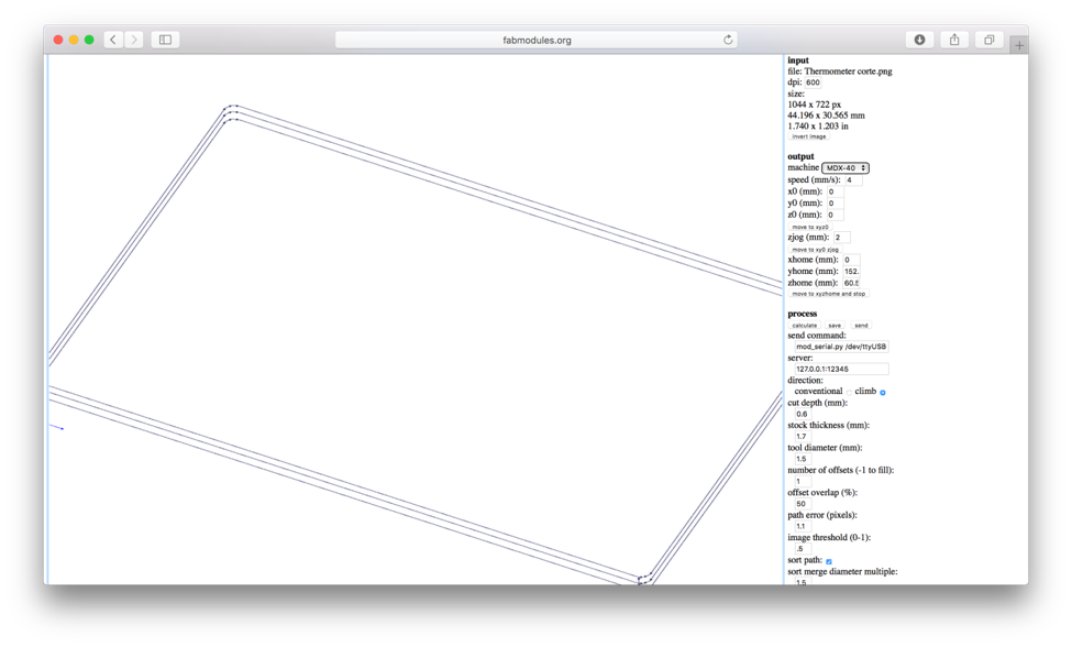
Interior Traces:
The First image
that I pulled up on the program is the interior traces of my board.
First I needed to select the image (.png), then I need to select the
output format which is Roland mill (.rml) and then I needed to select
process PCB traces (0.010). After I selected all the correct formats
and processes a side bar opened. The next thing I needed to do was to
correctly format the settings for input, output and process. First I
changed the dpi setting in input from 300.025 to 600.025 because, I am
using a MAC and I needed to double the input size. Then I needed to
configure the output settings. First I selected the MDX-40 for the
machine setting. Then I change the x0 and y0 setting from 10 to 0.
Finally I needed to change the process settings. The first setting I
needed to change was cut depth (mm) from 0.1 mm to 0.14 mm. Then I
needed to change number of offsets (-1 to fill) from 1 to 6 and then I
changed the offset overlap (%) from 50 to 70. The final step is to
click calculate bellow process in the side bar and then click save.
The Second image
that I pulled up on the program is the exterior traces of my board. The
process was similar but not the same as the first one. First I need to
select the image (.png), then I needed to select the output format
which is Roland mill (.rml) and then I needed to select process PCB
outline (1\32). After I selected all the correct formats and processes
a side bar opened. The next thing I needed to do was to correctly
format the settings for input, output and process. First I changed the
dpi setting in input from 300.025 to 600.025 because, I am using a MAC
and I needed to double the input size. Then I needed to configure the
output settings. First I selected the MDX-40 for the machine setting.
Then I change the x0 and y0 setting from 10 to 0. Finally I needed to
change the process settings. The only change I made to this setting was
changing the tool diameter (mm) from 0.75 mm to 1.5 mm. The final
step is to click calculate bellow process in the side bar and thenclick
save.
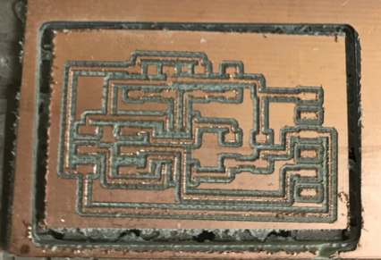
Once I completed
and saved the sketches I put them onto a pin drive so I can transfer
the files to the Roland mill to cut the board.Here is a video link of
the Roland mill cutting my design into the board:
https://www.youtube.com/watch?v=fsG7Pu9v7ks . Below is an image of what the board looks like after being cut.
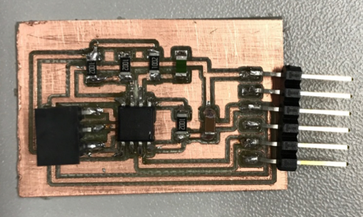
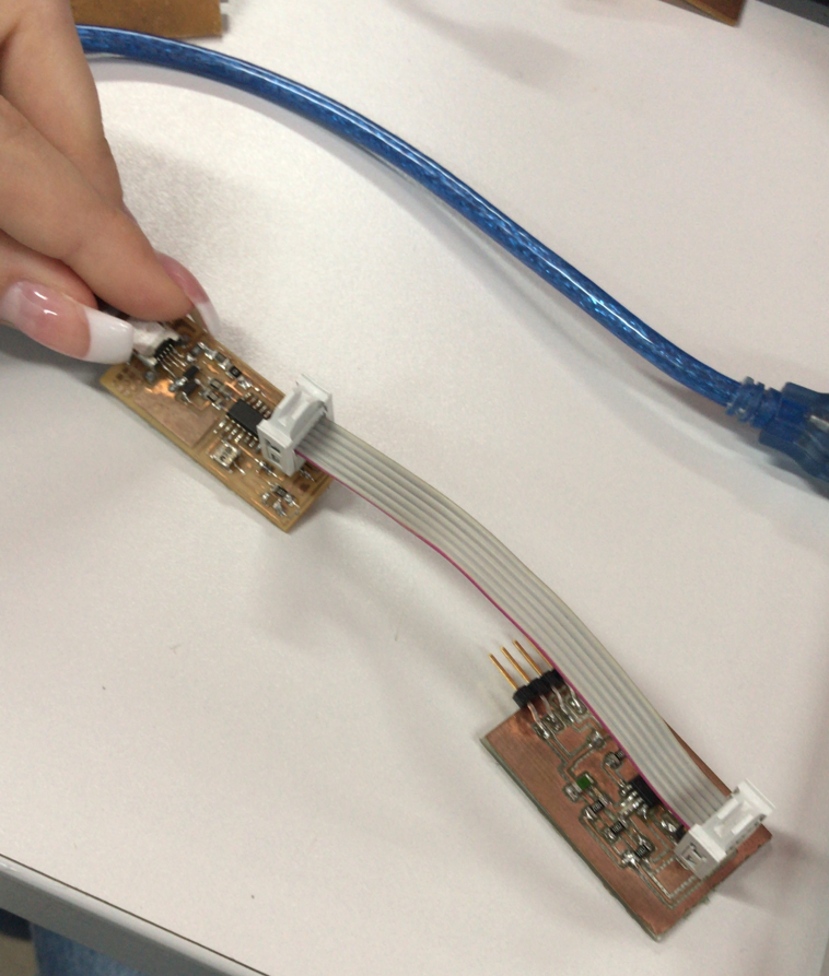
Once the board was cut I needed to file and smooth out all the sides of
the board including top and bottom. Then I soldered the components onto
the board as you can see below.
Note: This
step was difficult for me as I didn’t have much experience and the
parts are very small. I recommend taking your time in this process and
make sure you have a good grip on the parts before soldering.
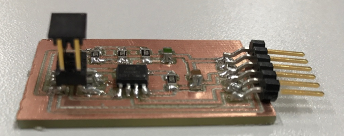
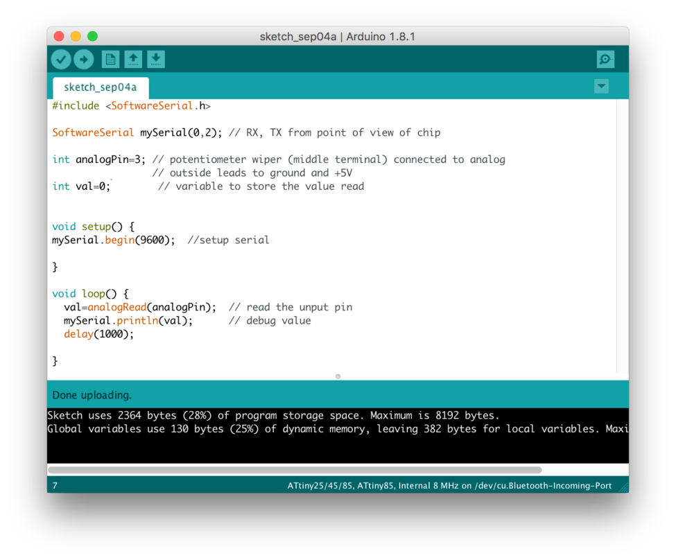
Programing board:
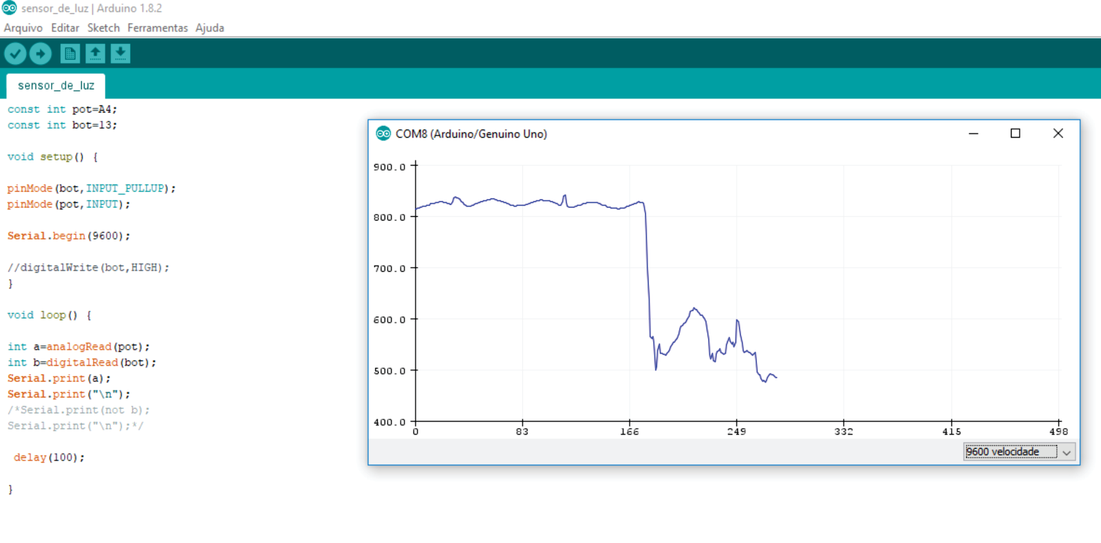
The Final step in this week’s project was to program the board. I used
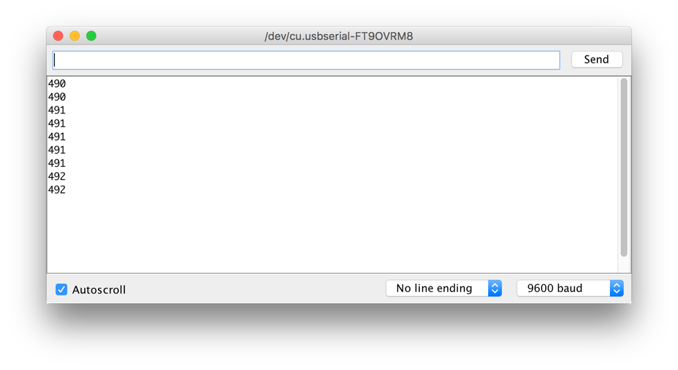
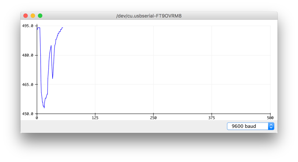
the Arduino software to program.The first program was reading a digital
value on the port, it was generating values around 490. Which obviously
showed that the thermometer was not working properly. My instructor
told me that I should program the thermometer to generate a temperature
value in degrees Celsius.
I connected the ISP programmer to the board, and followed the process
to load it into the microcontroller. Make sure your Arduino IDE is set
to program the aTTiny, as I mentioned in the “Embedded Programming”
assignment and in the following page:
http://highlowtech.org/?p=1695
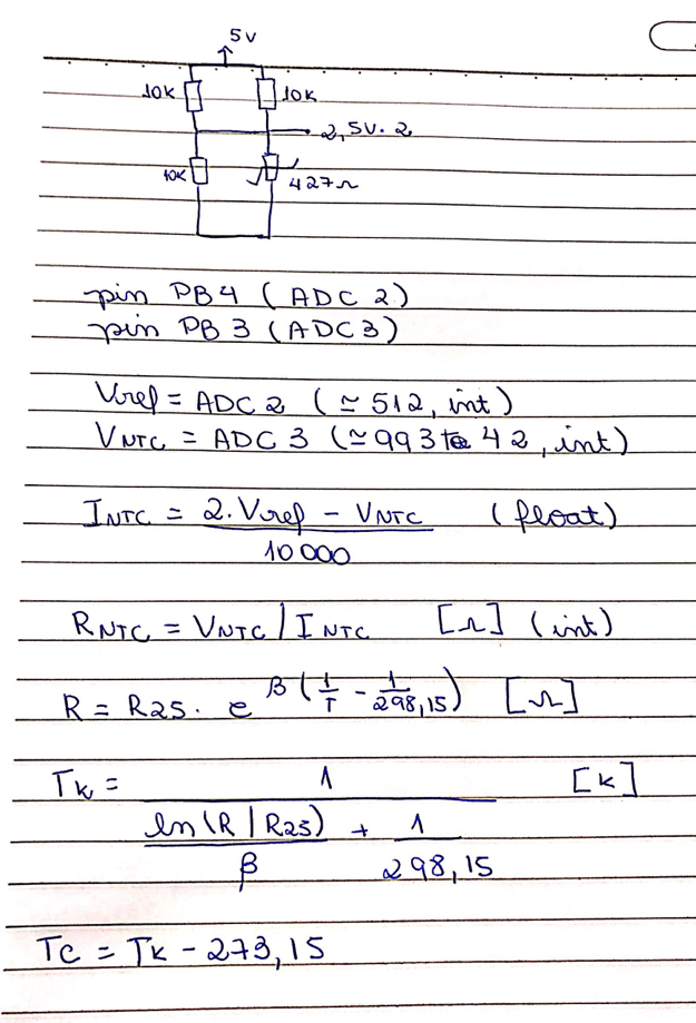
I had help from a Fab technician to do the following math, since he is a graduate in electrical engineering.
Also, I read
this tutorial to help me out.
I used the following math to correct the mistake.
Now the thermometer works as you can see in the pictures and video link:
https://youtu.be/ExZFiTMnLbI
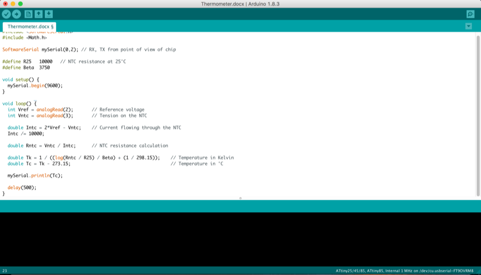
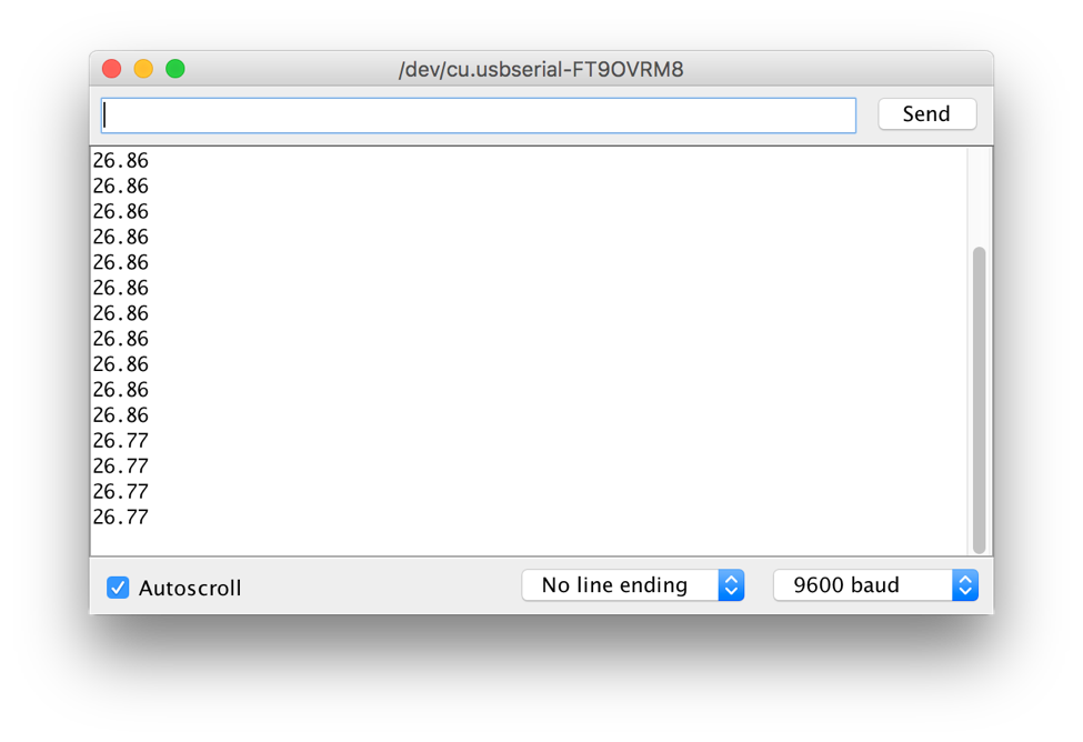
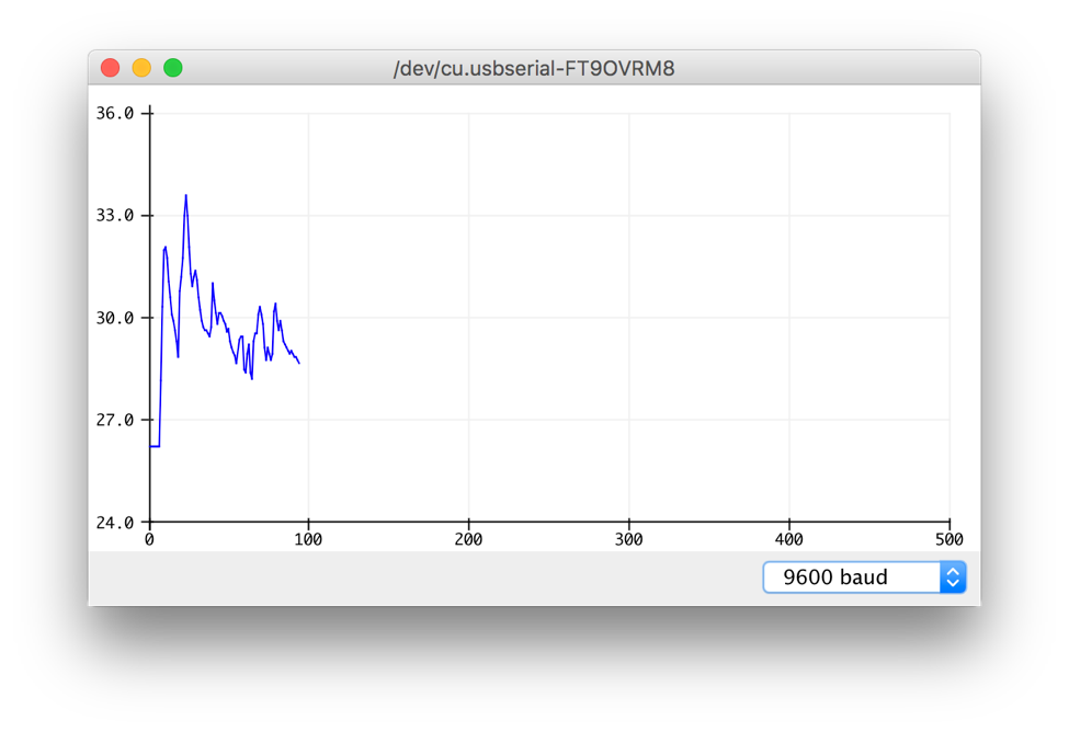
In the picture below you can see when I programmed the board.
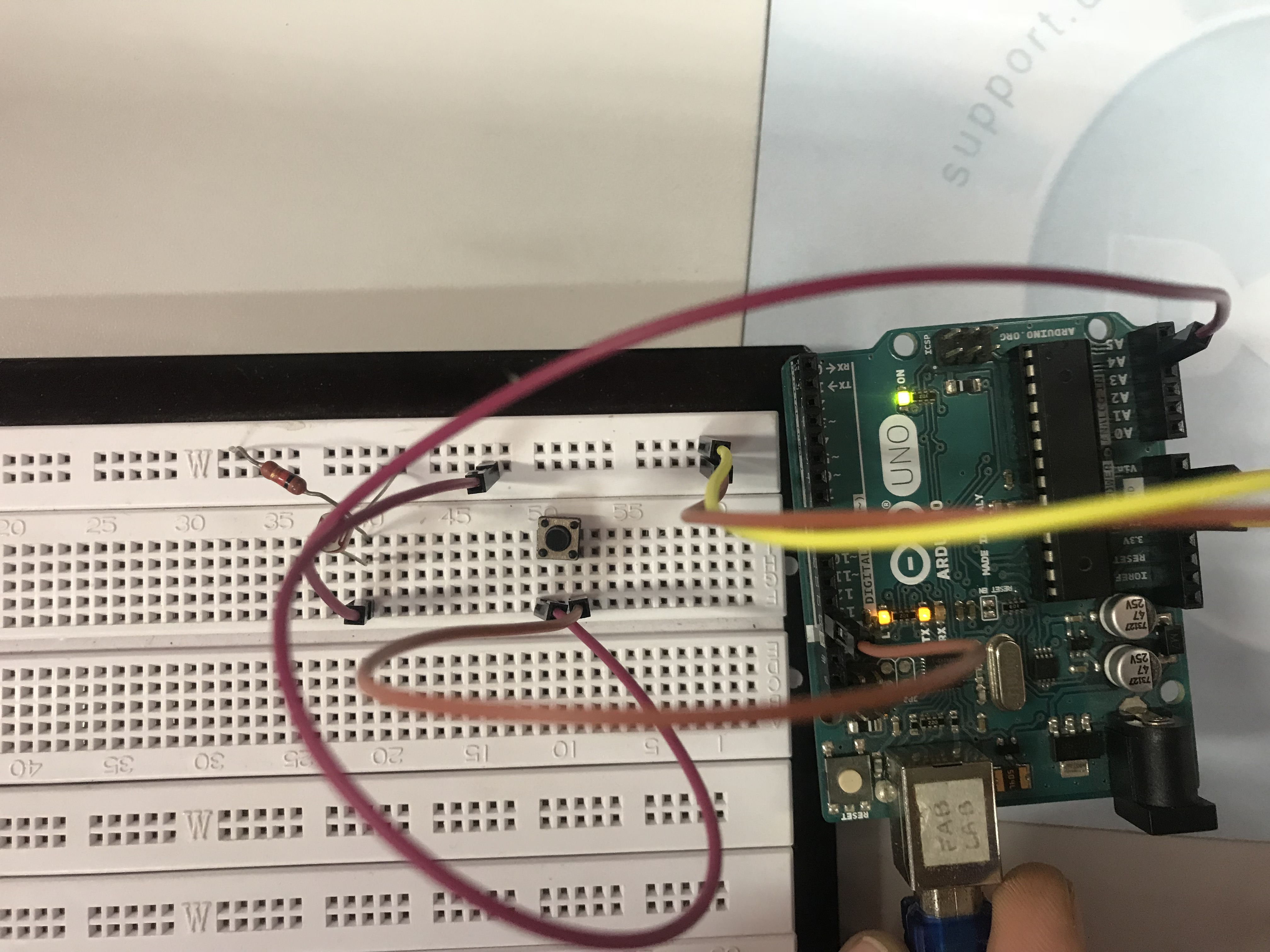
Measure the analog levels and digital signals in an input device
I
used an Arduino to test and read the value of two different input
devices. The first is an LDR (light independent resistor) that measures
the luminous intensity and the other device is a button. The LDR will
be used as an analog measurement and the button to perform the digital
measurements.