 ASSIGNMENTS
Networking and Communications
This week's assignment was:
- Design and build a wired &/or wireless network connecting at least two processors.
In the interface and application week I used the HC-05 Bluetooth.
Material:
- FTDI cable for serial: 28AWG
- 3x Atiiny 85 (At our Fab Lab we did not have the Atiiny 45)
- 1x 6pin header
- 3x 10k resistors
- 3x luF capacitors
- 3x 2x2 4posheader
- 3x LED (White)
- 3x 1k resistors
- 3x 6posheader
- FR1 phenolic paper
Designing the Boards
FTDI cable for serial: 28AWG
Tx-Transmits
Rx-Recieves
Serial Bus:
Bridge Board- runs transmit/receive to header
Node Board- power/ground/transmit/receive
Multiple connectors on one cable
I designed my boards off the Serial Bus boards provided in the weekly
assignment page. Which can be accessed through the links below:
http://academy.cba.mit.edu/classes/networking_communications/index.html
A serial bus communication is only two wires - one to send information (Tx) and other to receive information (Rx).
Serial interfaces stream their data to the boards connected to them.
Note that RX and TX labels refeers to the device itself. Therefore RX in the master board connects to the TX in the slaves one.
I've read some more information about serial bus on sparkfun website: https://learn.sparkfun.com/tutorials/serial-communication/all
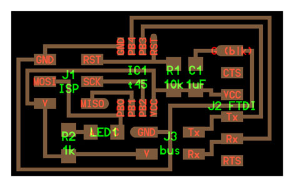
1x Bridge:
http://academy.cba.mit.edu/classes/networking_communications/bus/hello.bus.45.bridge.png
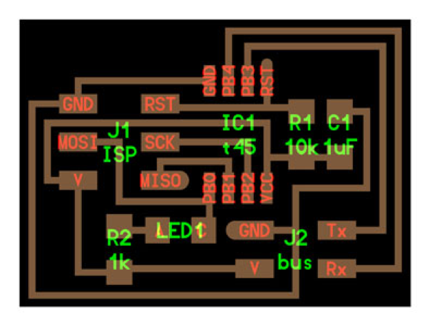
2x Node:
http://academy.cba.mit.edu/classes/networking_communications/bus/hello.bus.45.node.png
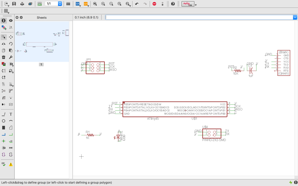
Eagle:
If you can’t remember how to use eagle to design your boards click on the Week 4
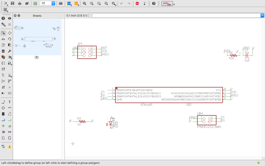
After evaluating the components and what I would need on my board I
went to Eagle to start designing the board. I made the bridge board
first.
Since the node boards are so similar all I had to do was to save as and
then changed the name and removed the header to easily design them. You
only need to design one node board and use the file to mill two
identical boards.
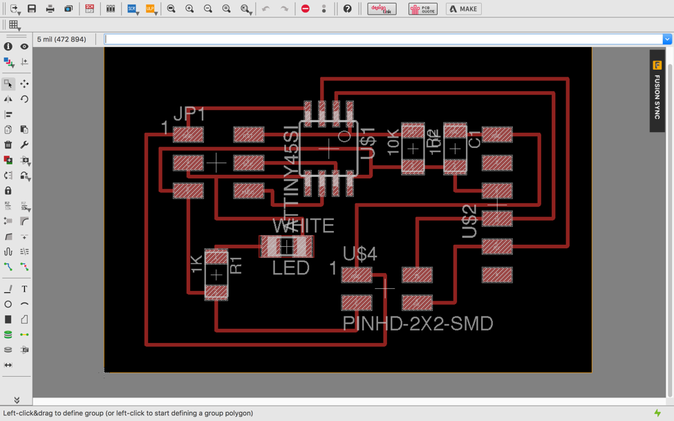
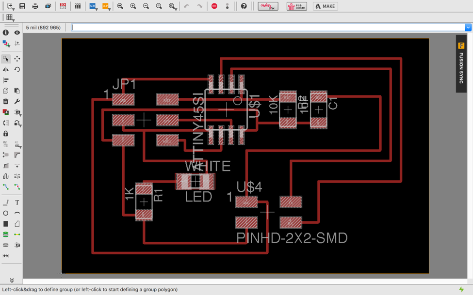
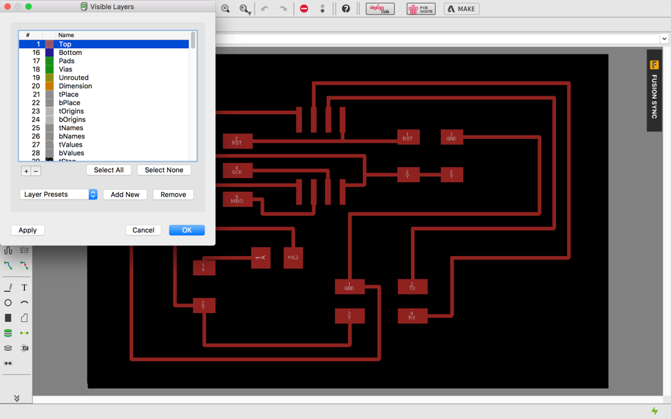
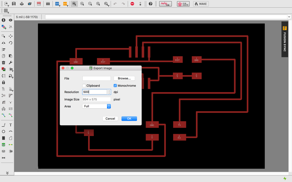
Then
I turned off all layers except the top and exported as an image-PNG. I
did this for both. After that I did the same steps but this time
selected the bottom layer. Don’t forget to change the resolution to 500
dpi and select monochrome.
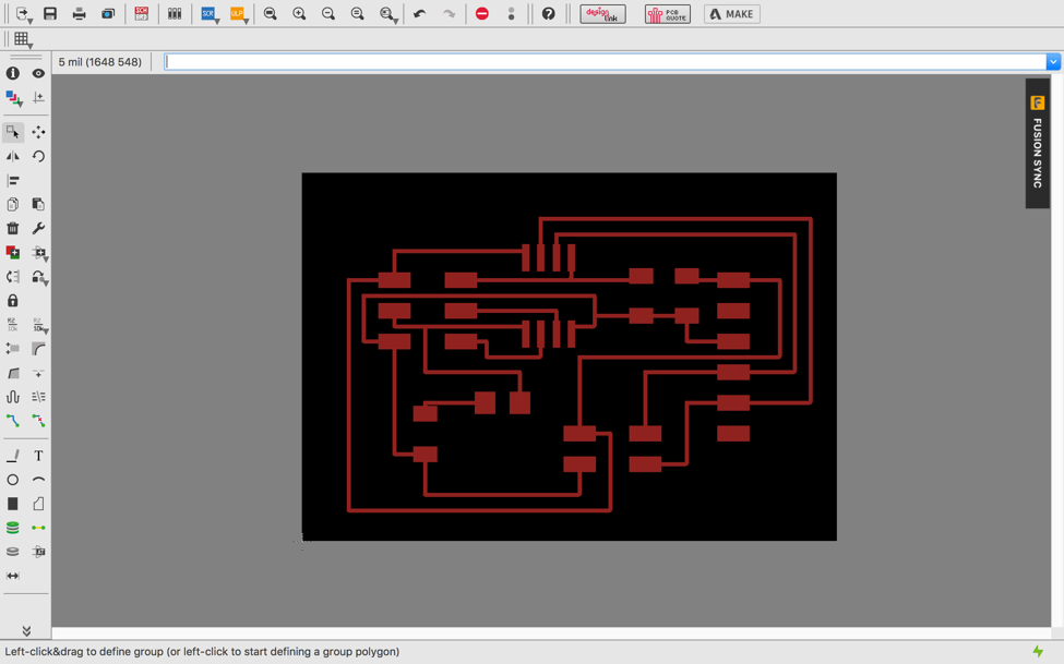
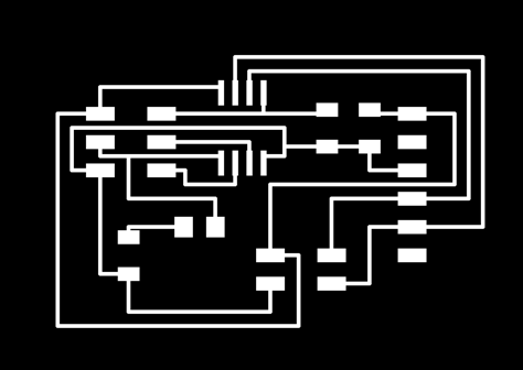
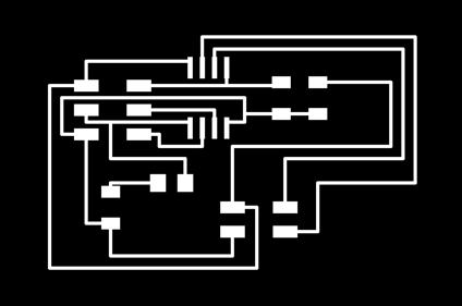
After I finished saving the files I now have the interior traces and outlines of my boards.
Bridge Board:
Node Board:
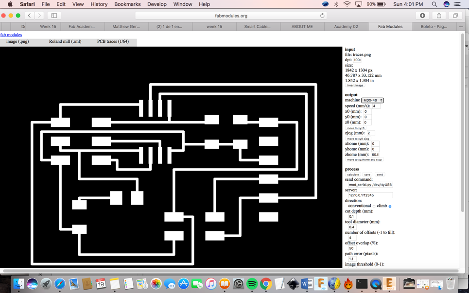
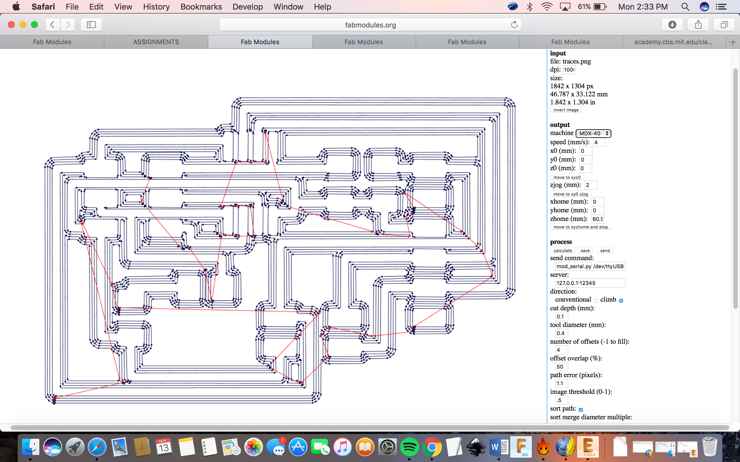
I then used the fabmodules.org to convert the traces/outlines to Rolland mill (.rml). Always remember if you are using a mac to change the dpi to 1000.
Then
I went to our Rolland Mill MDX- 40, zeroed the machine and then ran the
code. I first ran the Bridge board and outlines. Then repeated the same
steps twice to make the Node boards and their outlinesHere is a video
of me milling the board: https://youtu.be/vqdhW-839RE.The
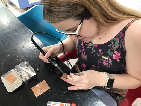
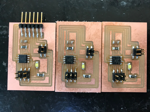
next step after milling of the boards was to gather all my components
listed in the materials list to be soldered onto my boards. Also
connect the boards with the FTDI cable for serial: 28AWG. Below are
pictures of this process.
Programing the Boards
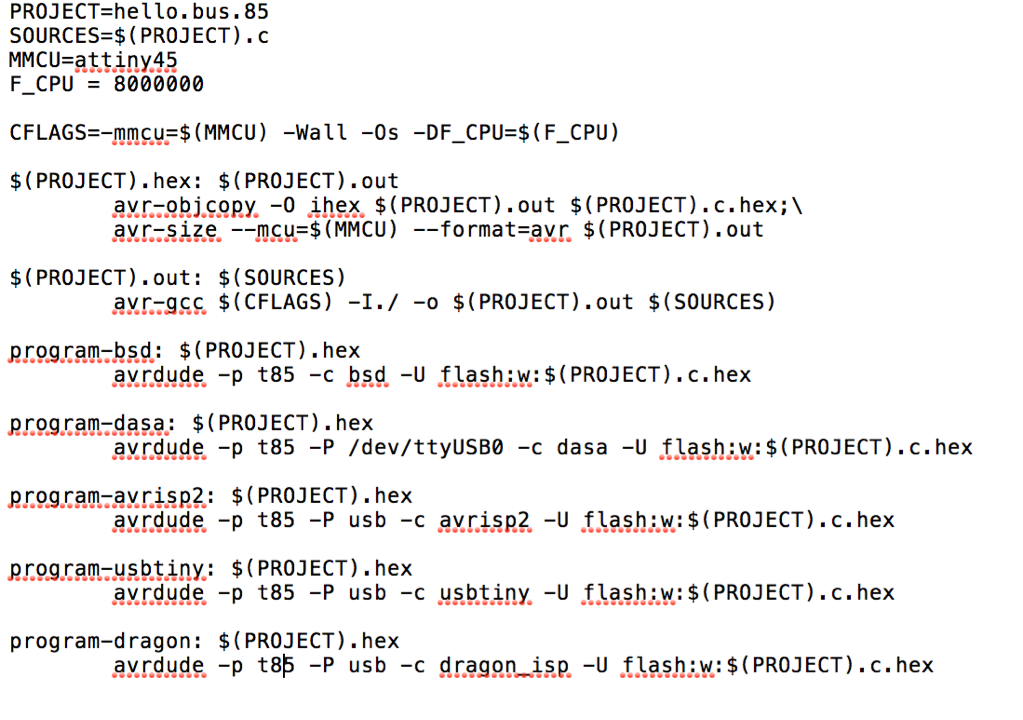
I downloaded the C code and the Make file and did some modifications on
them before programming. Below are the links for the downloads.
C File:
http://academy.cba.mit.edu/classes/networking_communications/bus/hello.bus.45.c
Once the C file is downloaded I opened it up on TextEdit to edit the
project=hello.bus.45 to Project=hello.bus.85 and to change everywhere
it says t45 to t85. The Reason for this is that we used the Attiny 85
instead of the Attiny 45.
Makefile:
http://academy.cba.mit.edu/classes/networking_communications/bus/hello.bus.45.make
Once I opened the Makefile in TextEdit I defined the bridge board by
changing where it said #define node-id ‘1’ to #define node-id ‘0. While
doing this process I only have the bridge board connected to my
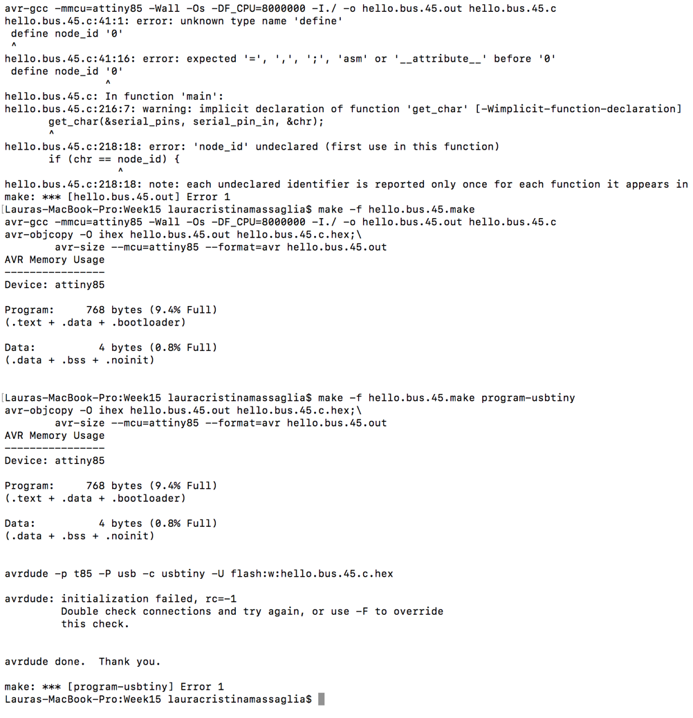
computer. I then ran the make file using:
sudo make -f hello.bus.45.make
sudo make -f hello.bus.45.make program-usbtiny
When I ran the program, it worked.
Then I defined my node boards as #define node-id ‘1’ and #define
node-id ‘2’. I connected the two node boards to the bridge board that
was still connected to the computer. I then ran the make file using:
sudo make -f hello.bus.45.make
sudo make -f hello.bus.45.make program-usbtiny
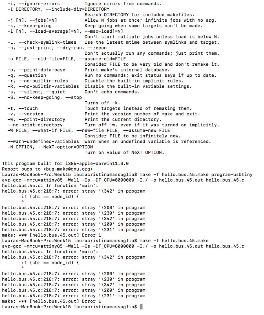
When I ran the program, it did not work.
I was not sure why it did not work and I asked my instructor to help
me. He could not figure out why it was not working on my Mac computer
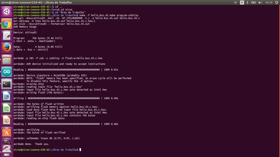
as well so, he instructed me to use his computer (Linux) to see if it
would run. It ran perfectly.
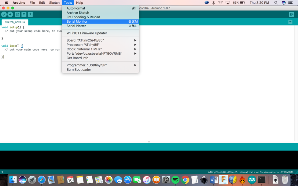
Arduino:
Then I opened the Arduino to run the program. I then went to Tools> Serial Monitor
Here is a video showing how a serial bus works.
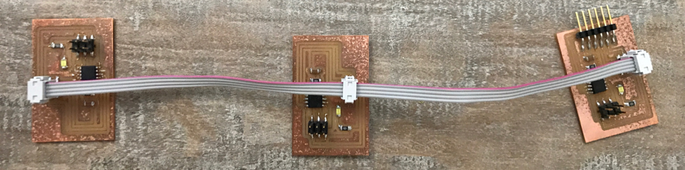
I have a bridge which has been connected to the computer through the
ftdi and two node boards(processors) which are connected to the bridge
through the same ftdi. Whenever I type 0 on the computer, all the
boards blink once but the bridge blinks two times. When I type 1, all
the boards blink once but node 1 blinks two times. When I type 2, all
the boards blink once but node 2 blinks two times. The boards are
communicating back to the computer to indicate that they have responded
to the initial communication.
Video of the boards working: https://www.youtube.com/watch?v=KLc9TMUjcIc
Project Files:
• Hello.Bus.45.bridge.Schematic Hello.Bus.45.bridge.sch
• Hello.Bus.45.bridge.Board hello.Bus.45.bridge.brd
• Hello.Bus.45.node.Schematic_ Hello.Bus.45.node.sch
• Hello.Bus.45.node.Board Hello.Bus.45.node.brd
• Hello.Bus.45.c Hello.Bus.45.make
• Hello.Bus.45.chello.Bus.45.c
• Bridge traces
• Bridge outline
• Node traces
• Node outline
|