Electronics Production
The assignments for this week were:
- To make an in-circuit programmer.
- Choose which type of in-circuit programmer to make, I chose the hello.ISP.44.
- Characterize the specifications of your PCB production process.
In
2018, I didn’t participate in a group project because I was the only
continuing/ Fab Lab Student.
I did the group project by myself.
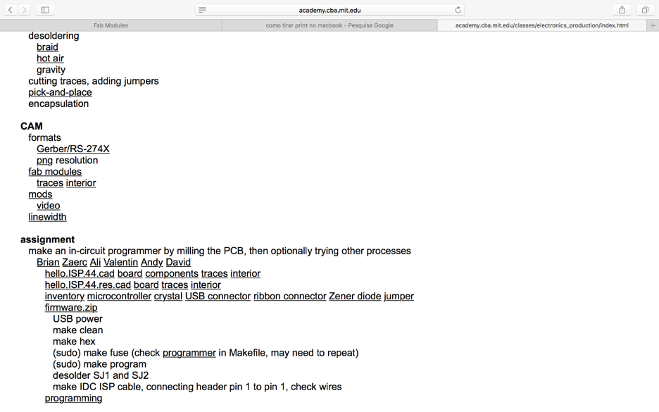
CUTTING AND MILLING THE BOARD
Inside Traces:
The Rolland
MDX40 machine doesn’t work with a pre-installed program but it does
through the internet: fablabmodules.org a program that allows us to
handle the machine from an internet browser. Fab modules is very easy
to use, when you open the website you click on input format- image
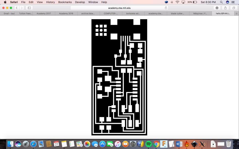
(.png), then you can chose your file, I chose hello.ISP.44 traces first
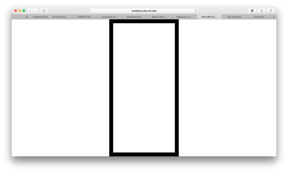
and then the outline, which I got from the Fab Academy class achieve-
assignment, as you can see below. First, you must choose the link that
says traces and an image will appear that the machine can read. The
images below help explain the steps.
You must then
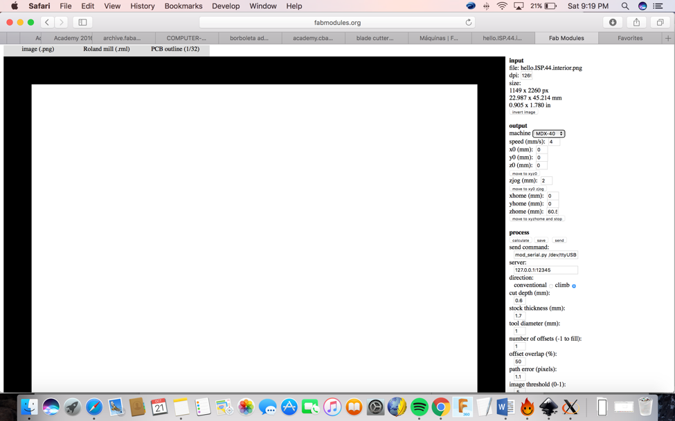
save the image of the outline. After this you open up the saved image
in the fabmodules browser by first choosing your file, you then click
on output format- Rolland mill (.rml), then click on process PCB traces
(1/64), after that you need to select the machine. In this case I used
MDX-40. Once you chose the machine, it will show you all the preset
parameters. I changed some of the preset parameters on the output
setting because I wanted the x and y axis to start from 0 mm not from
10 mm. These were the only preset settings that I needed to change.
x0 mm:10 to 0
y0 mm:10 to 0
yHome:152.4 to 0
Important Definitions:
X, y, z (0) = initial position of the tool
X, y, z (home) = the position where the tool
will end after milling position after machining - z (home) = must be a
positive and high number so as not to risk breaking the milling cutter.
Zjog = Safety margin for fast movement without milling.
Cut deph = approximates the thickness of the copper in the plate. Shows how deep the tool will cut into the board.
Offset = number of times the tool will mill the traces on the board
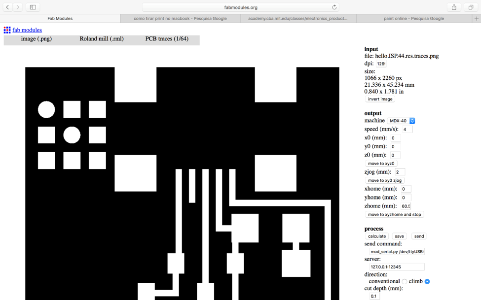
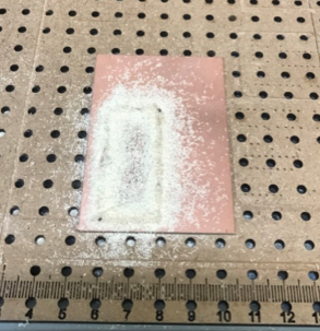
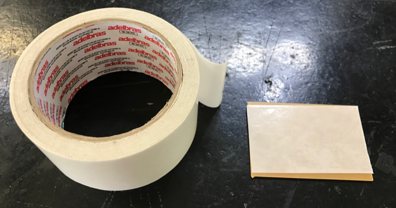
As you have noticed there is a side bar. The input settings are what image or file you are putting into the fabmodules. The output settings are how the fabmodules connects with the machine and where the machine in this case is going to start cutting. The process settings is where you can set how the tool will work. Once you are finished setting all your settings you then click on save, and your file will be ready. After that you need to choose your board material. I chose FR1 phenolic paper. Before you start cutting you should remember to put double-sided tape onto the bottom of the board and stick it on the machine. The tape holds the board stable while the machine is cutting.
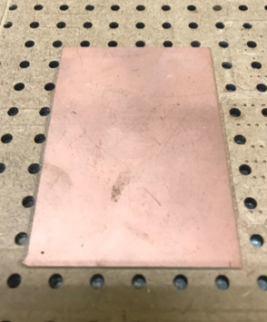
(
FR1 Phenolic Paper)
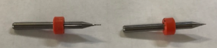
The first tool
endmill 0.4mm broke when the machine started because I chose a
setting (z axis) that cut the board to deep. The tool got stuck and
broke in the board. I replaced the tool with a new one but didn’t have
to replace the board as I just manually realigned the xy axis of the
machine allowing the tool to start at a different starting spot. The
new one is on the left, in the picture below.
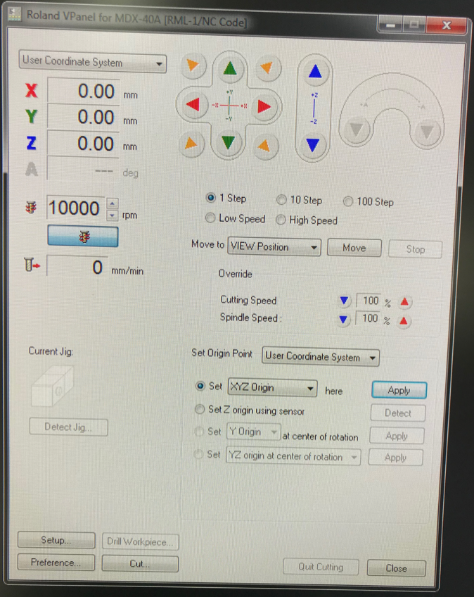
I then set up the x,y,z axis by using the V-panel (machine software).
You can watch a video here: https://youtu.be/anvxjhbdHJ8
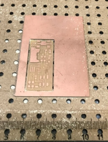
Outline:
After the end
of this process, you should go back to fabmodules.org and do the steps
for the outline of the board. I used a tool diameter of 1.5mm, a cut
depth of 0.5mm and stock thickness of 1.7mm.You can find a file at the
Fab Academy website - class achieve- assignment- hello.ISP.44 traces.
First you save the image.
Then
you open the image file in the fabmodules by selecting image
(.png)>Roland mill (.rml) > PCB outline (1/32) . As you can see
in the image below a setting side bar appears again. The next step is
to choose your settings. In output you chose the machine (MDX 40) and
both the x0(mm) and y0(mm) to 0. Then in the same output setting change
the yhome (mm) to 0. After that I needed to change tool diameter (mm)
to 1 in the process settings.
After this the outline of the board will be cut. At the end, you will
have your board ready and you just need to clean it up.
Then you clean up the circuit board and remove it from the machine and excess material.
If everything is done correctly, you should have a board like this:
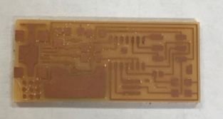
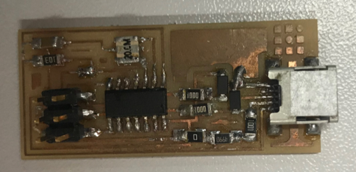
SOLDERING THE COMPONENTS
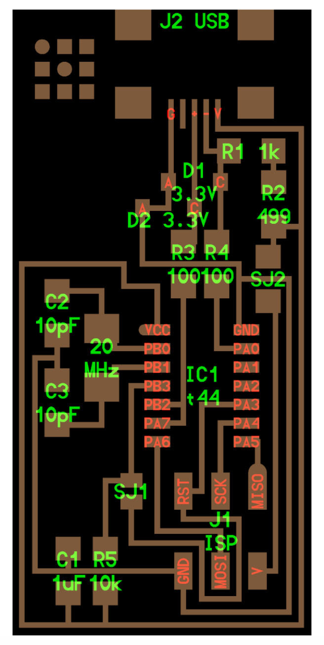
The components used:
• 1x ATtiny45
• 2x 1kΩ resistors
• 2x 499Ω resistors
• 2x 49Ω resistors
• 2x 3.3v zener diodes
• 1x red LED
• 1x green LED
• 1x 100nF capacitor
• 1x 2x3 pin header
The next step is to solder the components listed above onto the board. I used a soldering iron and solder for the
components to stick on the board. You first take the solder and
soldering iron and then heat the solder to stick to the board. Then you
use a tweezer to pick up the component (metal legs facing downward)
with one hand and in the other hand the soldering iron. Then when you
have a good grip of the component heat up and melt the pre-solder from the previous step with the soldering iron and place your component legs down
into the melted solder. Wait until the solder spreads on the copper pad
surface and the component to make sure that there is an electrical
connection between them.
Comments: I didn’t know how to solder a component before this class, but I was very excited to start, I
thought they look very cute, although when I started to solder I
realized that it was a very delicate and really hard job. A Fab Lab
instructors helped me to get my first component soldered, he taught me
some tricks to do it, and after one hour I could almost get my board
finished.
After soldering all the components, you need to check the electrical circuit of your board. I used a multimeter to check the electrical connection. After doing this step and checking I confirmed the electrical connection was good.
The Software Installation
The very first
step one has to do before they can build and program firmware onto
their board is to download a program that will allow them to set up a
development environment. This will be the set up that you use for most
of your programing. You'll also have to use command line shell (bash)
in your platform's terminal to execute all of the commands below. If
you are unfamiliar with using the command line, you can review them at
this link :review a tutorial.
Importnant Definitions:
Command: is an instruction given by a user telling a computer to do something.
Shell: is a
program that reads commands that are typed on a keyboard and then
executes (i.e., runs) them. Shells are the most basic method for a user
to interact with the system.
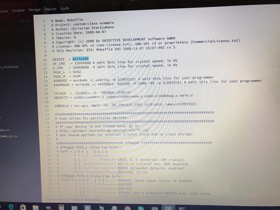
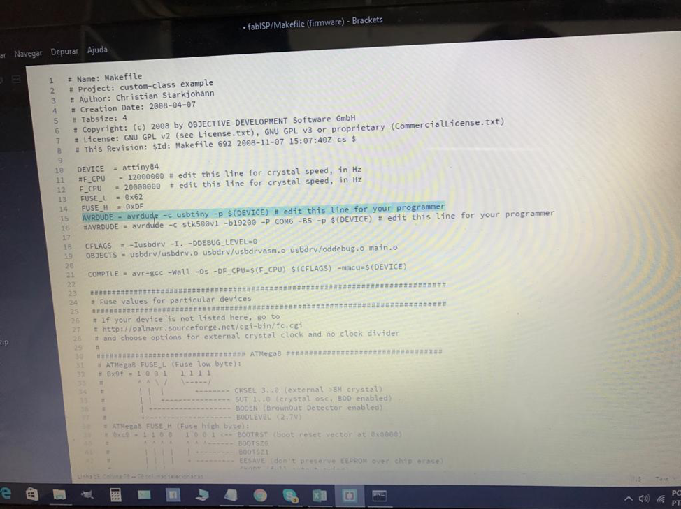
Get and Build the Firmware
Since I use Mac Book, I first downloaded and installed CrossPack.
Download and Install: CrossPack
Coding legend:
make clean - removes all autogenerated files.
sudo xcodebuild -license - install and accept the license necessary to program it
make clean - removes all autogenerated files.
make hex - builds the .hex file.
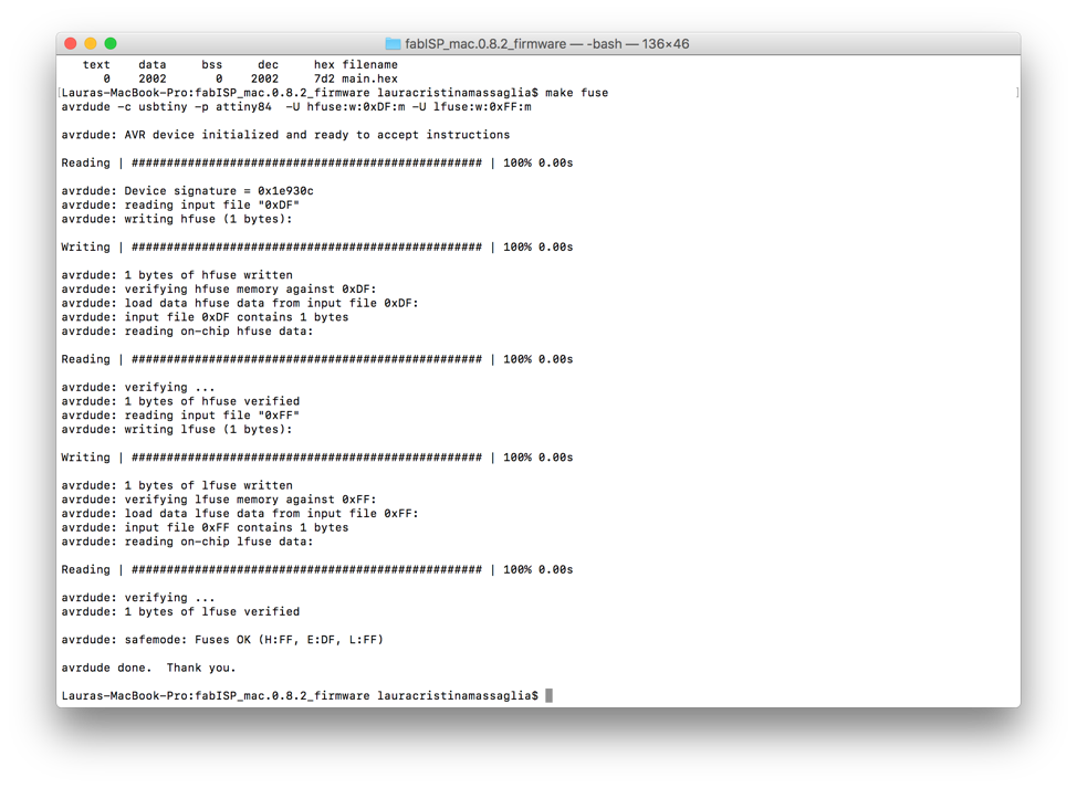
make fuse - programs the fuse bits on the target chip.
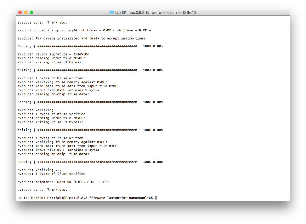
make program - Upload the program to the chip, so that this board can be used as an ISP.
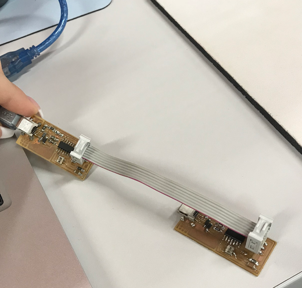
I used another FabISP programmer to program my FabISP.
There was already another fabISP programmer available at the lab. So, I used it to program my new fabISP.
Below is a photo of the FabISP connected to the computer when I programed it.
Make sure you connect the flat cable and the 2x3 header in the correct position. As showed in the picture below:
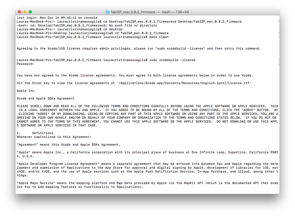
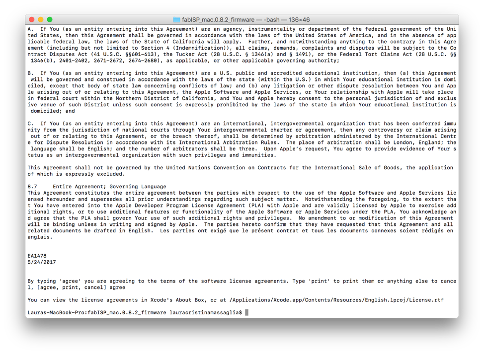
The second step one needs to do is download the firmware source code
from the Fab Academy resources and extract the zip file. Open your
terminal program, type cd into the source code directory and then click
enter. The next step is to type in cd desktop and then click enter.
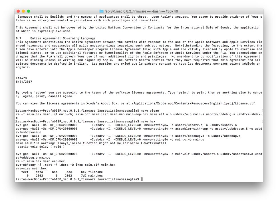
Then type make clean. Make clean command deletes all the already
compiled object files. Then a list of software license agreements will
appear. After that you have to read and agree to them by typing in
agree. Then again type in make clean and then type make hex. The make
hex command creates a hex file which is used to describe locations in
memory. This hex file will get programed into the ATtiny45. Once you
are finished programing minimize or close the terminal and go to Finder
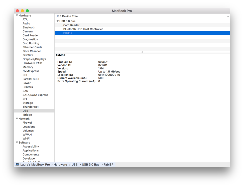
(Apple at the top left corner of your toolbar)> Click About this
mac> Click System report> Click USB and you will see FabISP. This
means that your program is ready and your board can now be accessed via
USB to your computer.If the command doesn't complete successfully,
something is wrong with your toolchain installation. Consult the error
messages for information that will help you debug it. See programing
process in the pictures below: