output Devices
This week's assignment was:
- To add an output device to a microcontroller
board that we previously designed and program it to do something.
- Measure the power consumption of an output device.
Desinging And Milling Microcontroller Board
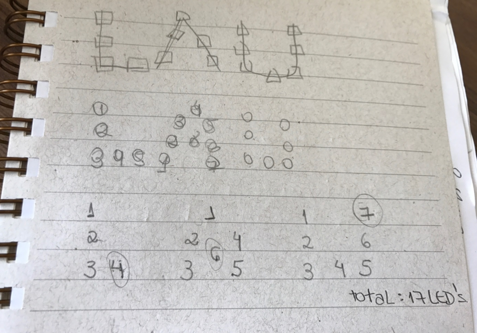
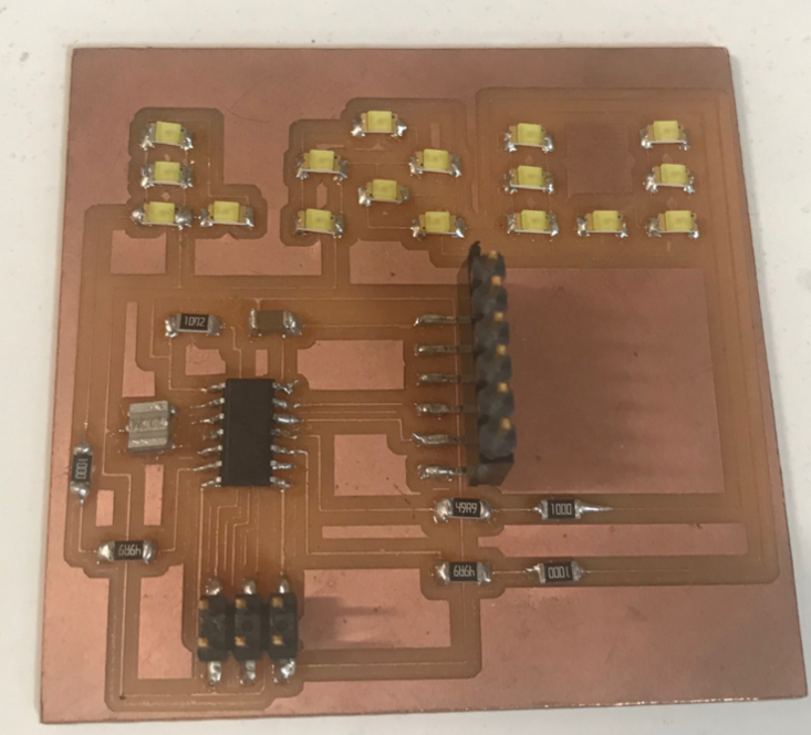
I decided to work with LED. I wanted to make something with my name,
more specific, with the first three letters of my name LAU.I used a
piece of paper to
draw a few rough sketches to see the best way to lay out the LED lights
for the lettering.
Letter L = 4 LEDs (pin 6)
Letter A = 6 LEDs (pin 10)
Letter U = 7 LEDs (pin 11)
This also allowed me to have a better understanding
on how the lettering and LED design would look once I started to design
it using the Eagle program.After a few rough sketches, I realized that
I needed 17 LED’S. I decided to use white LED’s for my lettering. After
I chose my design and LED’s I started drawing my board using the Eagle
program.
Note: I
describe how to use eagle and all the after steps in week 6 (Make blue
link to week 6), if you have any doubts on how to use eagle click on
the
Week 6.
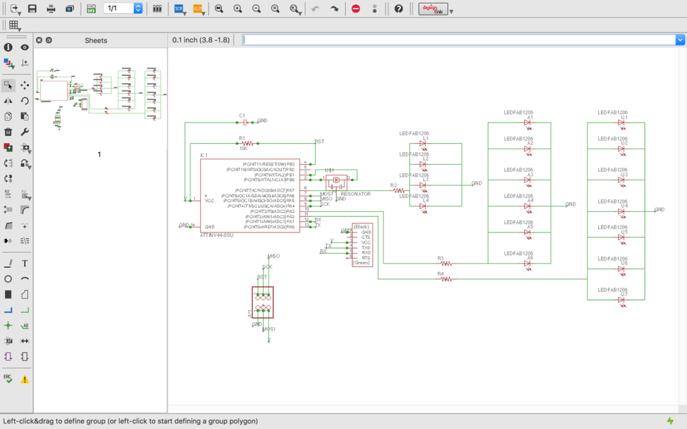
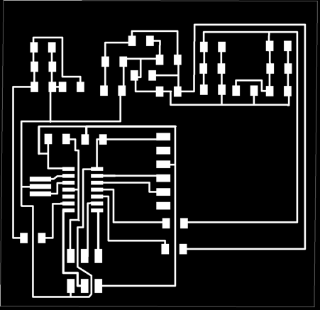
I first started
with designing the schematic by putting the resistors in series using
eagle as you can see in the above picture. I gave names based on the
letter and number of LED’S, for example: L1 first resistor of the
letter L. After I finished the schematic, I switch to board on eagle to
connect the components, as you can see in the image below.
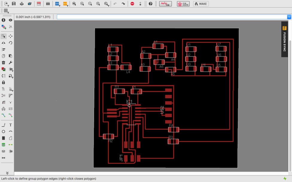
In the image below, you can see where I placed each component.
When I design the board, I didn’t put some resistors as needed. So,
when I was soldering I added the resistors to the board, it worked
perfectly.
Then I exported the file as a png (file > export > image). Made
sure the settings were set to MONOCHROME and 500 DPI. This will export
an image with white traces. I also made sure the color mode was set to
greyscale (image > mode > greyscale). Then I exported the
Dimension layer for milling the outside of the board.
Note: Always
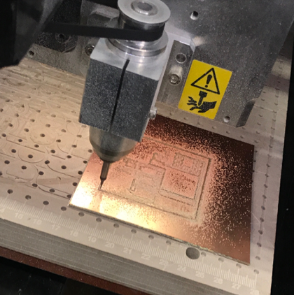
remember that the Modela cuts out the dark and white areas. Then I generated the interior and exterior of my board using gimp.
The components I used:
17 white LED’s
1 x Attiny 44
1 x capacitor 1uF
3 x Resistor 100 Ω
1 x Resistor 10 kΩ
3 x Resistor 49.9 Ω
1 x 2x3 pin header
1 x pin header
1 x resonator 20MHz
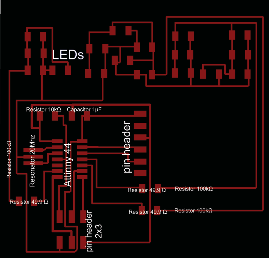
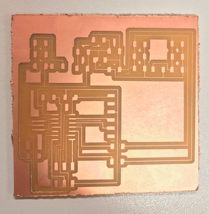
The
results were perfect and as you can see in the image above the LAU is
designed to perfection at the top, and below is my board as the machine
works.
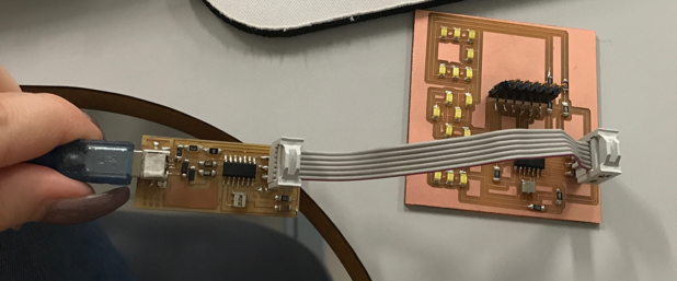
I then soldered on the components and contacted output device to the microcontroller board
.
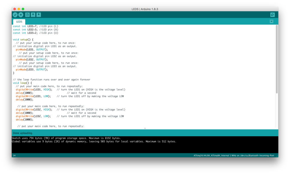
First I wrote the program in the Arduino IDE. I checked the arduino pin
reference for each microctroler pin. The program is pretty simple, and
lights on and off each letter, by “digitalwrite” and “delay”
routines. I commented the programming with the function of each
line.
I connected the ISP programmer to the board, and followed the process
to load it into the microcontroller. Make sure your Arduino IDE is set
to program the aTTiny, as I mentioned in the “Embedded Programming”
assignment and in the following page:
http://highlowtech.org/?p=1695
If you have any doubts about how to program the board click on the link:
http://highlowtech.org/?p=1695
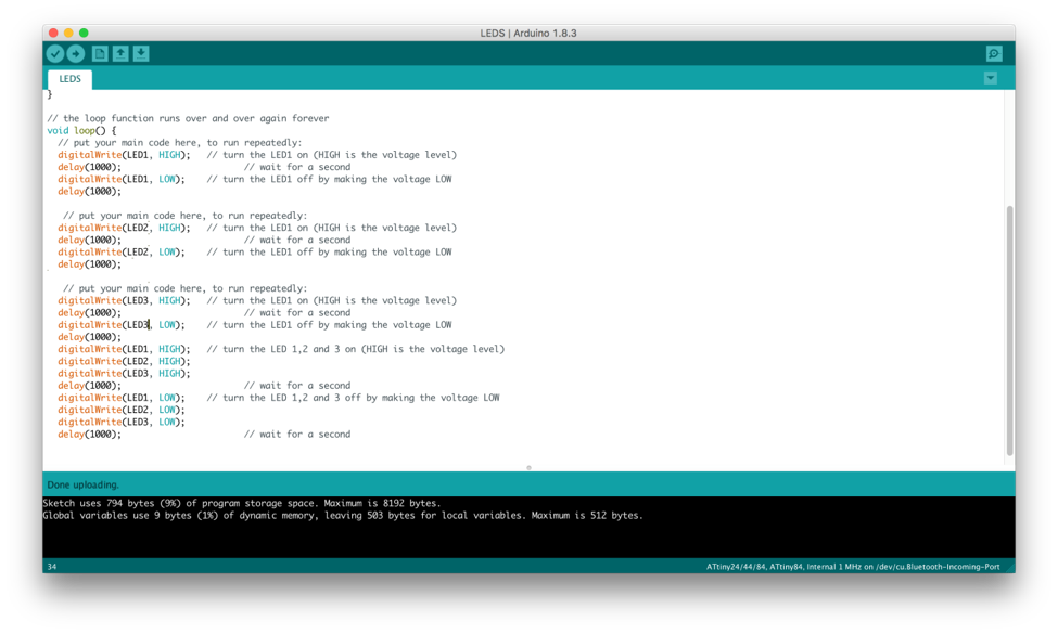
The next thing I had to do was program the board using Arduino. Below
are pictures of what the programing looks like. My first initial
thought and attempt a sequence in which the L first turned on, then the
A and then finally the U. After the first initial sequence of the LEDs
turning on I then wanted all the LED lettering to turn on all together.
It didn’t work and I was very disappointed. My instructor told me that
my programing was correct, so I started to try to find out what was
causing the error. My primary thoughts were, that if my programing was
correct the error had to be caused by the resonator not working or the
tracks connecting to the micro controller were too thin. I checked for
errors using a tool called a multimeter. This tool is used to measure
current, resistance, or voltage. After testing, I came to the
conclusion that the resonator was working and the tracks were not too
thin. This made me realize that it had to be something else.
Bellow is my Ardruino and my programming:
After checking over my board I realized I had put on a resistor that
was 10 ohs instead of 10K . The resistors look exactly the same just
have a different output. This was the error that caused the LEDs not to
turn on.
I changed the resistor using the hot air to remove the first one. Then
soldered the 10K resistor, programmed it again and it worked perfect,
as showed in the video above, also in a picture below:
Watch the video here:
https://youtu.be/s56dioSO_9w

