Week 2 - Computer Aided design
This week's tasks are:
- Evaluate and select 2D and 3D software.
- Demonstrate and describe processes used in modelling with 2D and 3D software.
- Modelled experimental objects/part of a possible project in 2D and 3D software.
Step1: Getting introduced to CAD and some concepts
When I learn about a topic I always prefer to learn about the basic concepts and what does it mean.what is CAD? what are the different programs techniques.
These are some definitions that I learned about:
- Computer Aided Design (CAD):the use of computer systems to aid in the creation, modification, analysis, or optimization of a design.
- Raster:the type of design where it’s made of pixels each with a different color arranged to display the whole design or image. It’s resolution dependent.When you zoom in to the image or shape very closely or scale it to larger size you can see the pixels mush clearer.
- Vector:the type of design which is made of paths, each with a mathematical formula that describes how it’s shaped and what color it’s in. it’s resolution independent.When you zoom in to the image or shape you still can see the lines very smooth and continous.
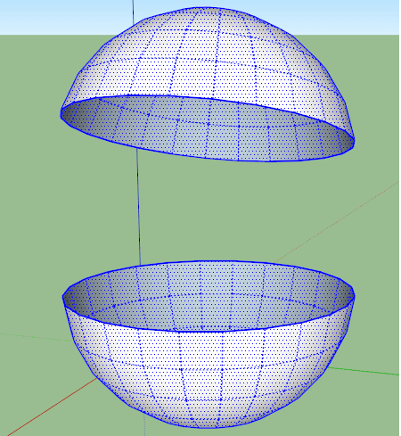
- Mesh (Polygon): The type of design where any 3D object is divided into many surfaces that forms your it's shape. Usually these small surfaces are with Triangular shape.
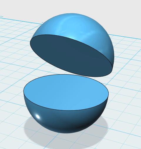
- Surface (Solid): The type of design where any 3D object is shaped by mathematical formulas.
Also in 3D designing there is a very much close concept:
For digital fabrication specially 3D printing it's always better to work with a surface software not mesh as meshs always cause a lot of problems.
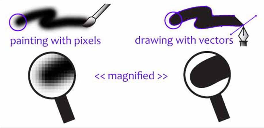
Vector Vs Raster
Mesh
Surface
Step2: Trying different 2D design softwares
Photoshop
Photoshop is a 2D raster software where we can edit and create 2D designs. I use it to edit my photos to be uploaded to the website. I find that it's more suitable for artistic designs not for Engineering ones.I have a compitable version from a friend of mine and I experminted eiditing, Layers concepts, Adding multiple layers, Free transform, Coloring, Compressing and resizing.
Detailed steps can be found here
Inkscape
I made a quick walkthrough in inkscape to discover it's features by creating a medal with my name.Inkscape is a vector free software where you can create different designs. It can do some from both Engineering and Artistic designs.I experminted Creating Shapes, Writing texts, Adjusting object properties, Navigation, Resizing, scaling and exporting DXF.
Detailed steps can be found here
Step3: Trying different 3D design softwares
I Tried before Google Sketchup and Fusion 360 and this is a comparison between both of them
| Google Sketchup
|
Fusion 360
 |
|
|---|---|---|
| Timleline | No | Yes |
| Parametric Design | No | Yes |
| Parameters Editing | Yes | More easy and friendly |
| Constrains | No | Yes |
| Cloud based | No | Yes |
| Collaborative enviroment | No | Yes |
| Usage | used more by architectures to create cities and buildings makets | used more for engineering designs like mecanisims, gears,...etc |
- Timeline:The ability to go back to any certain point in the deisgn, edit something and it will affect the final result so that you don't have to repeat your design from the begining if you wanted to change anything.
- Parametric design:To make the design parameters related to equal or in a relation wiht a certain value that can be changed anytime. This helps when the design has parameters relate to each other.
- Parameters editing:Change the value of anyparameter anytime.
- Constrains:Making a relation between shapes like making a line which must be parallel to another line or prepndicular on it.
- Cloud based:The designs are stored in the cloud and you can acess it from any PC connected to the internet with your user account and password.
- Collaborative enviroment:Where you can share the design with a team or other friends to be able to edit on the design process.
Step4:Creating expermintal parts for a possible final project
For making press fit boxes there are a lot of webplatforms like : Maker Caser and Make a box where you can set the dimensions of the box that you need to laser cut and also set some other parameters and the platform will make you the design which you can download and it's ready to be laser cut with pressfit.
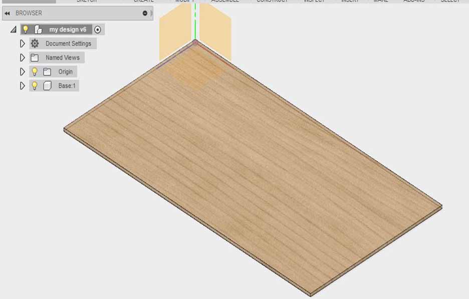
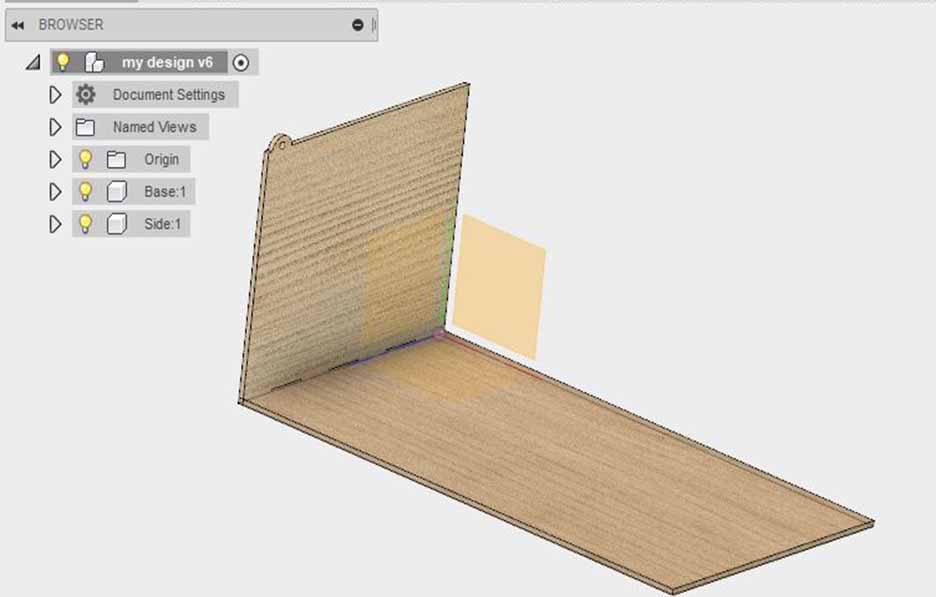
I wanted to create my own box using fusion 360 to make it as an enclosure for my final project circuits. and make it parameteric where you can change the width, depth and height and all the box will be adjusted with the fitting.
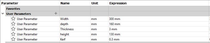
set the parameters of depth, width, height and kerf.
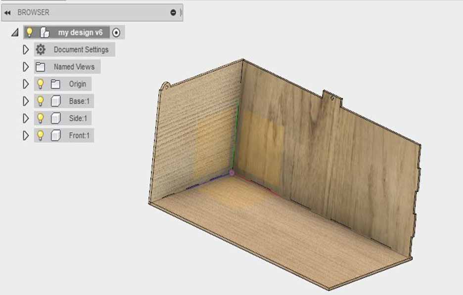
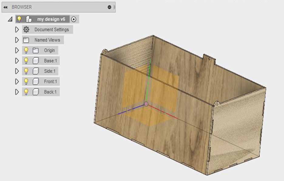
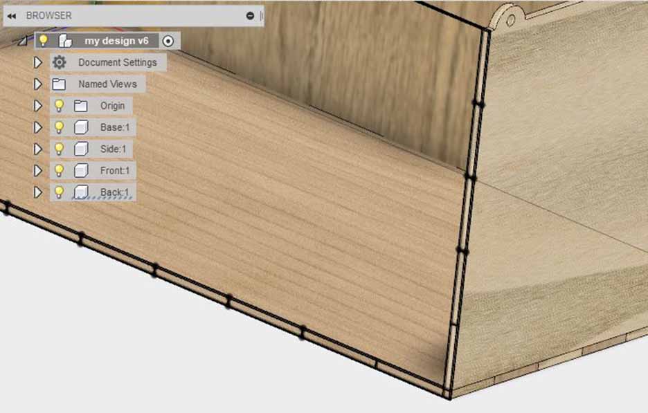
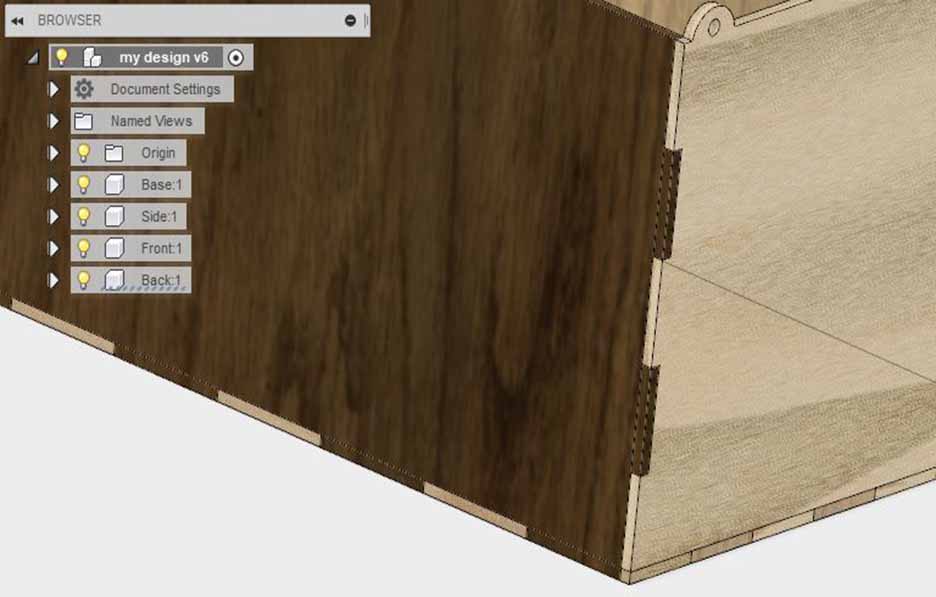
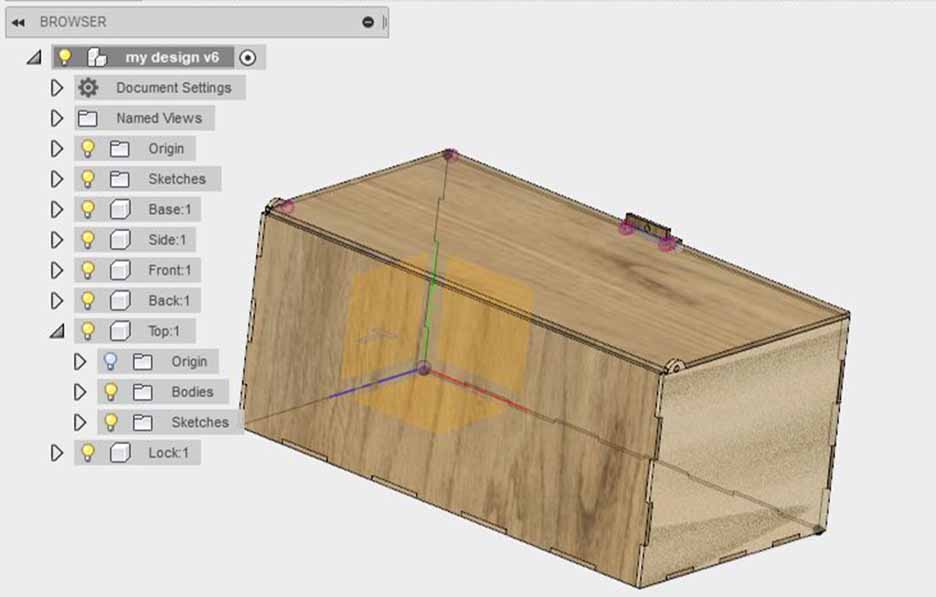
I decided to make it with cover to be able to use it for other purposes also. The cover can be removed and made as the bottom. For more detailed instructions on how to use Fusion 360 and parametric design check Computer Aided design documentation.