Week 3 - Computer Controlled Cutting
This week's tasks are:
- Characterize the laser cutting machine and test different materials ( group assignment).
- Make parametric press-fit construction kit.
- Cut Something on the viynl cutter.
Step1: Testing the machine
As a group assignment Everyone chose a material to test on the laser cutting machine. For me I went to Samir & Aly stationery house and got 3mm and 5 mm Balsa wood.
- Test suitable power and speed for the material
- Very small power values before 10 don't affect the material specially with high speeds.
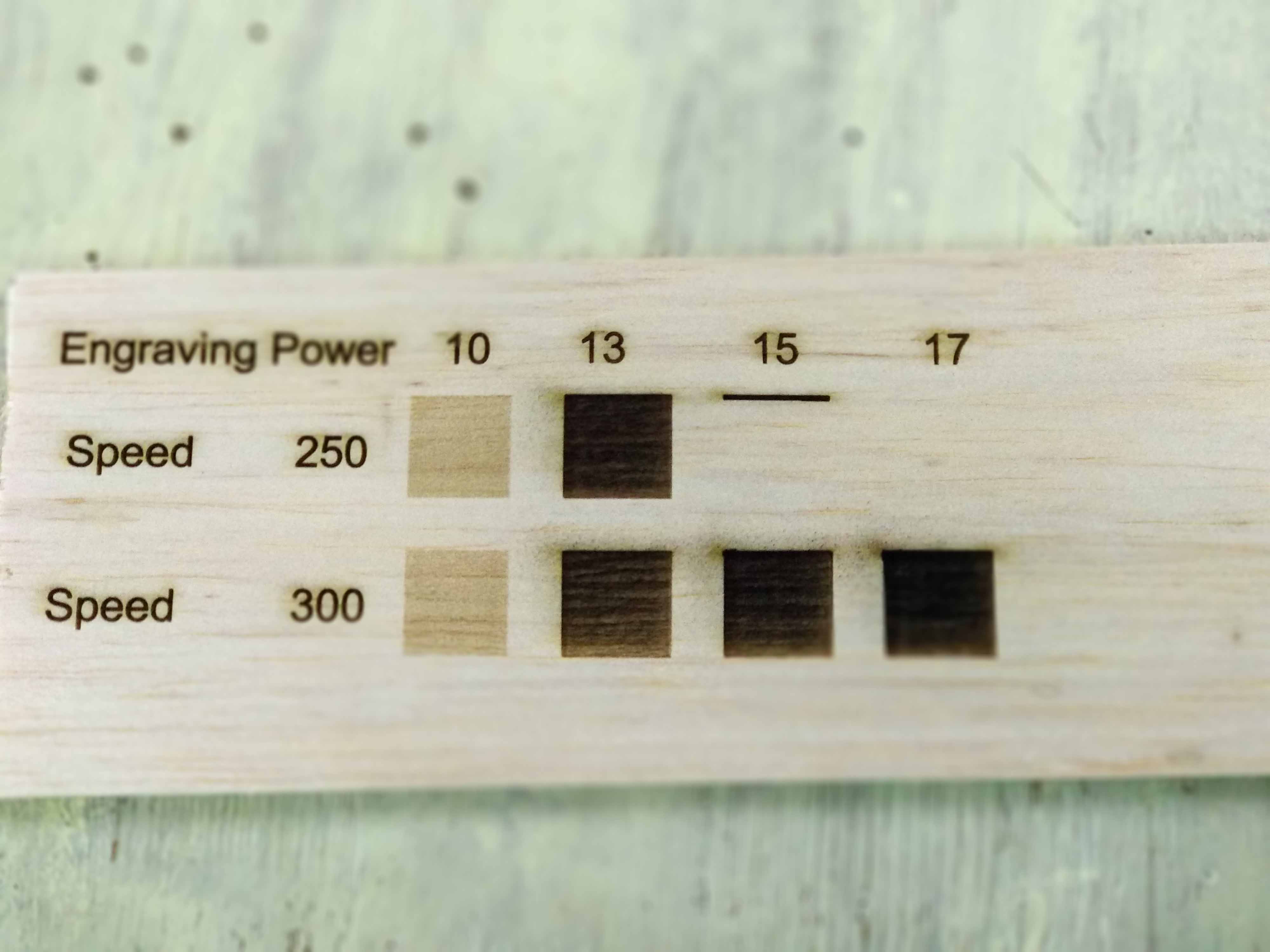
- The opitimum values for laser cutting and engraving Blasa wood are:
- Test the machine kerf
- The machine kerf is 0.1 mm
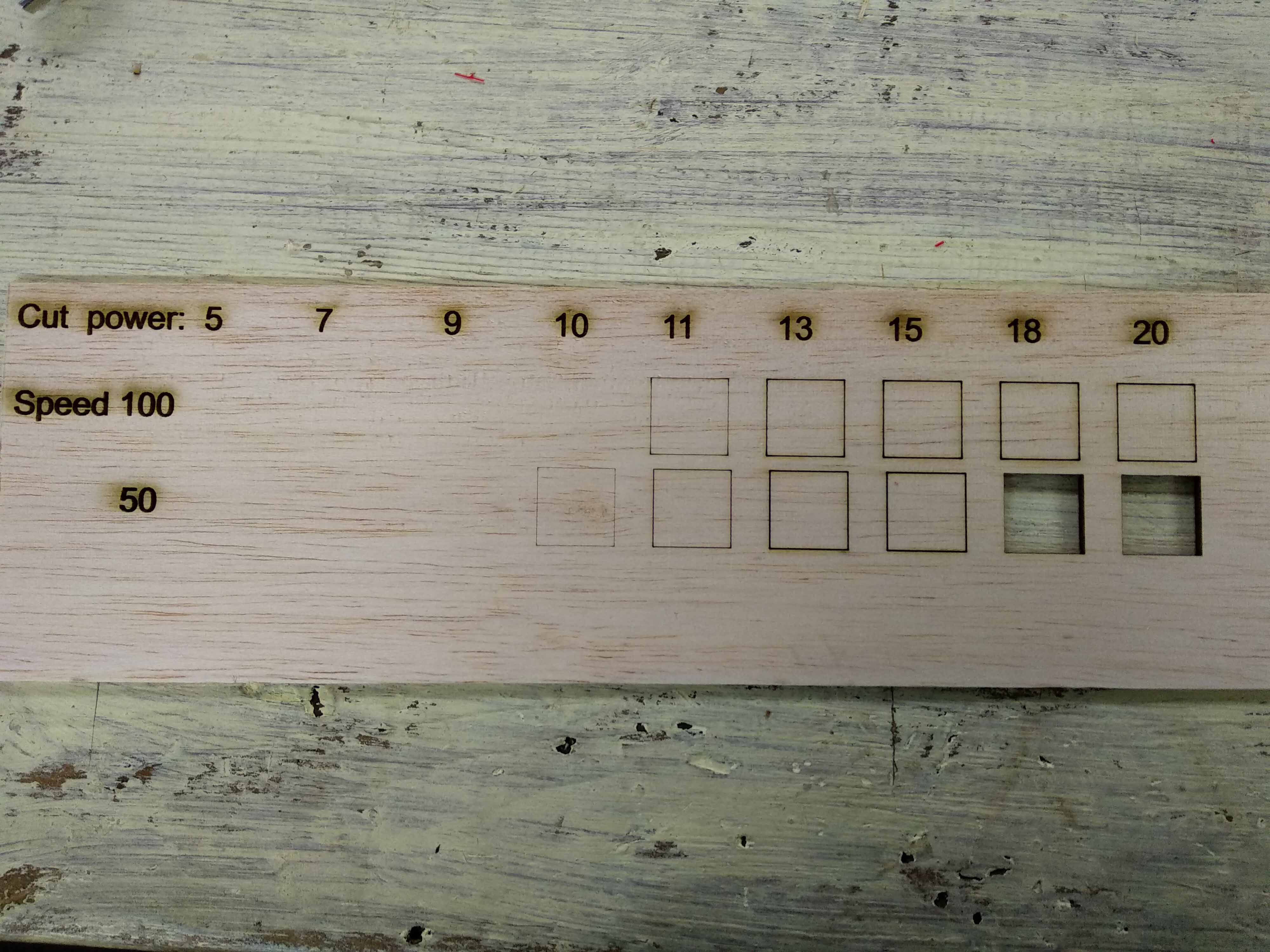
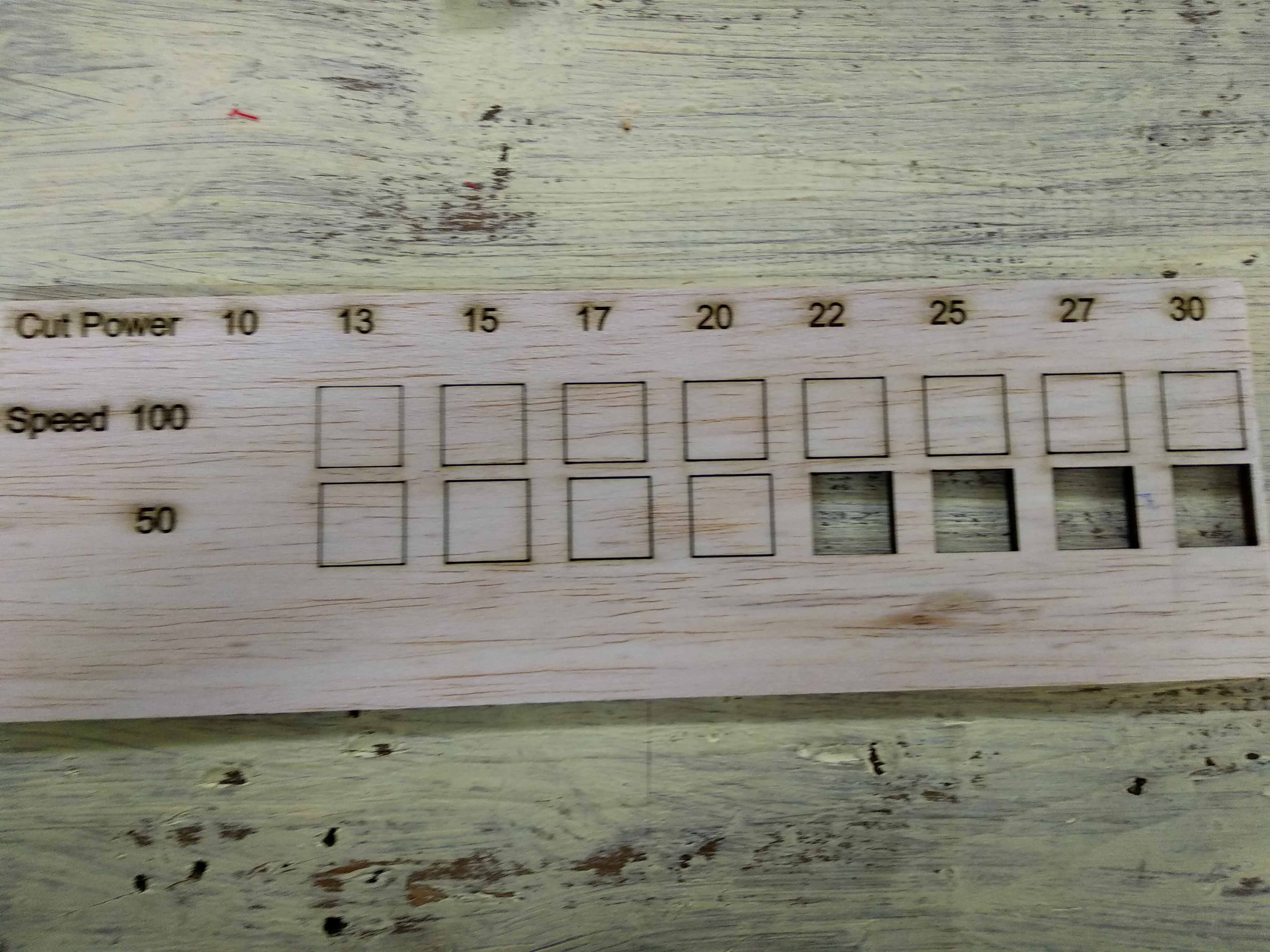
I used the test file designed by khaled as part of the group assignment.The test file is many squares that given different values for power and speed.
I used coreldraw software to edit on the file and write different power and speed values using the adding text tool. Then color each square with a different color.
Coreldraw software has an extension to Laserwork Which is the software for our laser cutting machie. So After finishing editing I press run then in Laserwork I was able to give different values for each color.
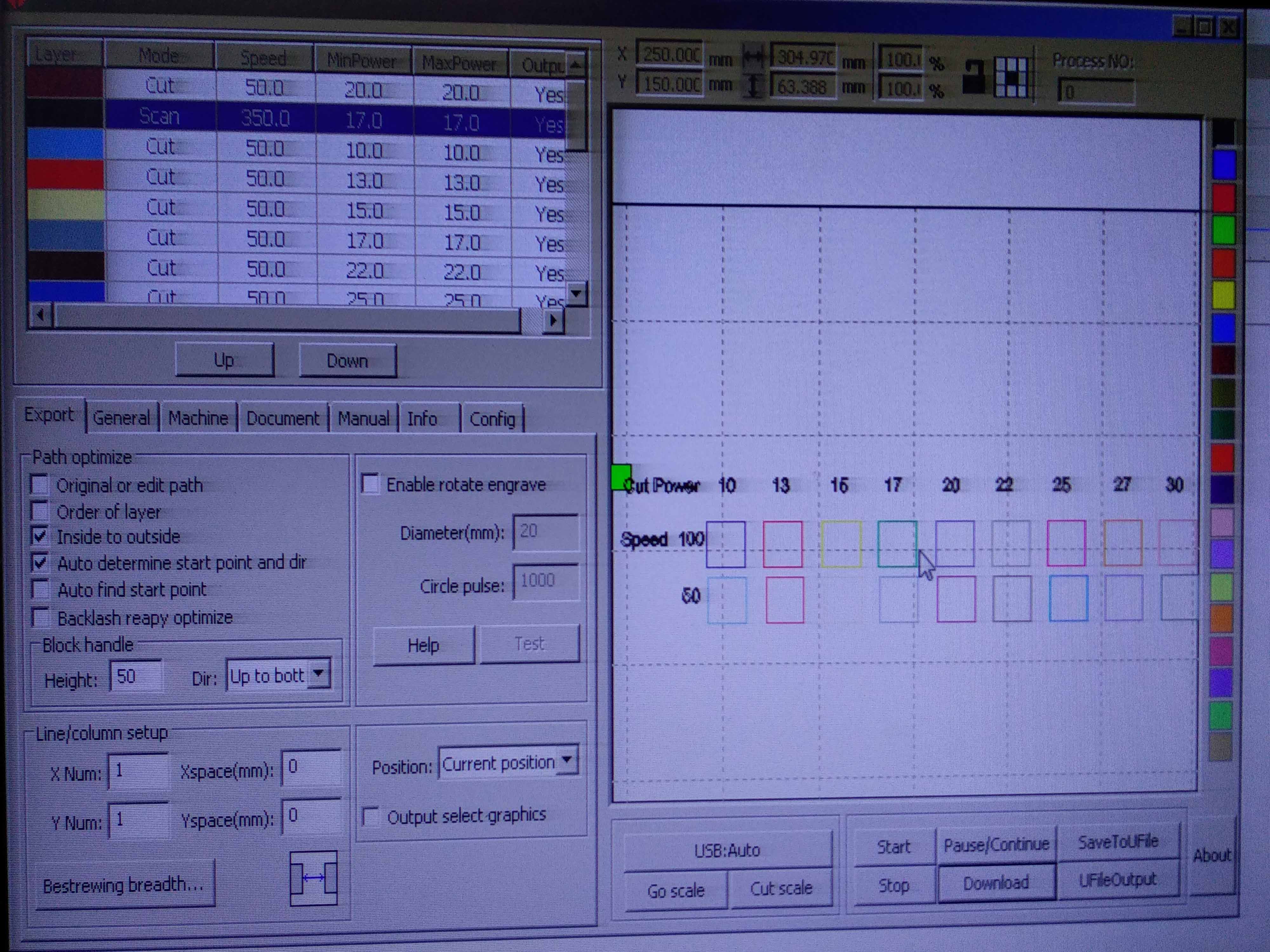
Giving different values for each color in laserwork
3mm Balsa wood cut results
5mm Balsa wood cut results
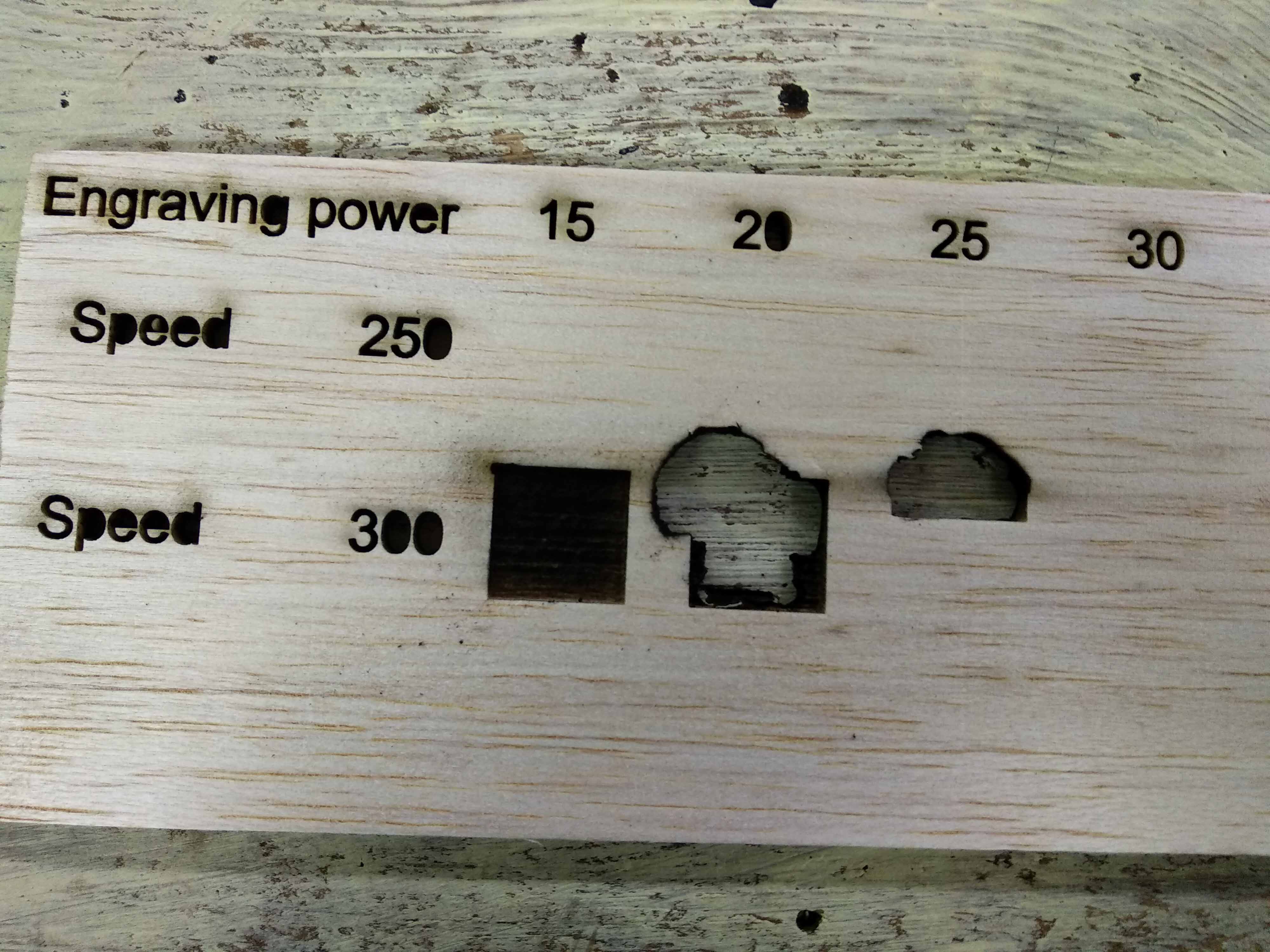
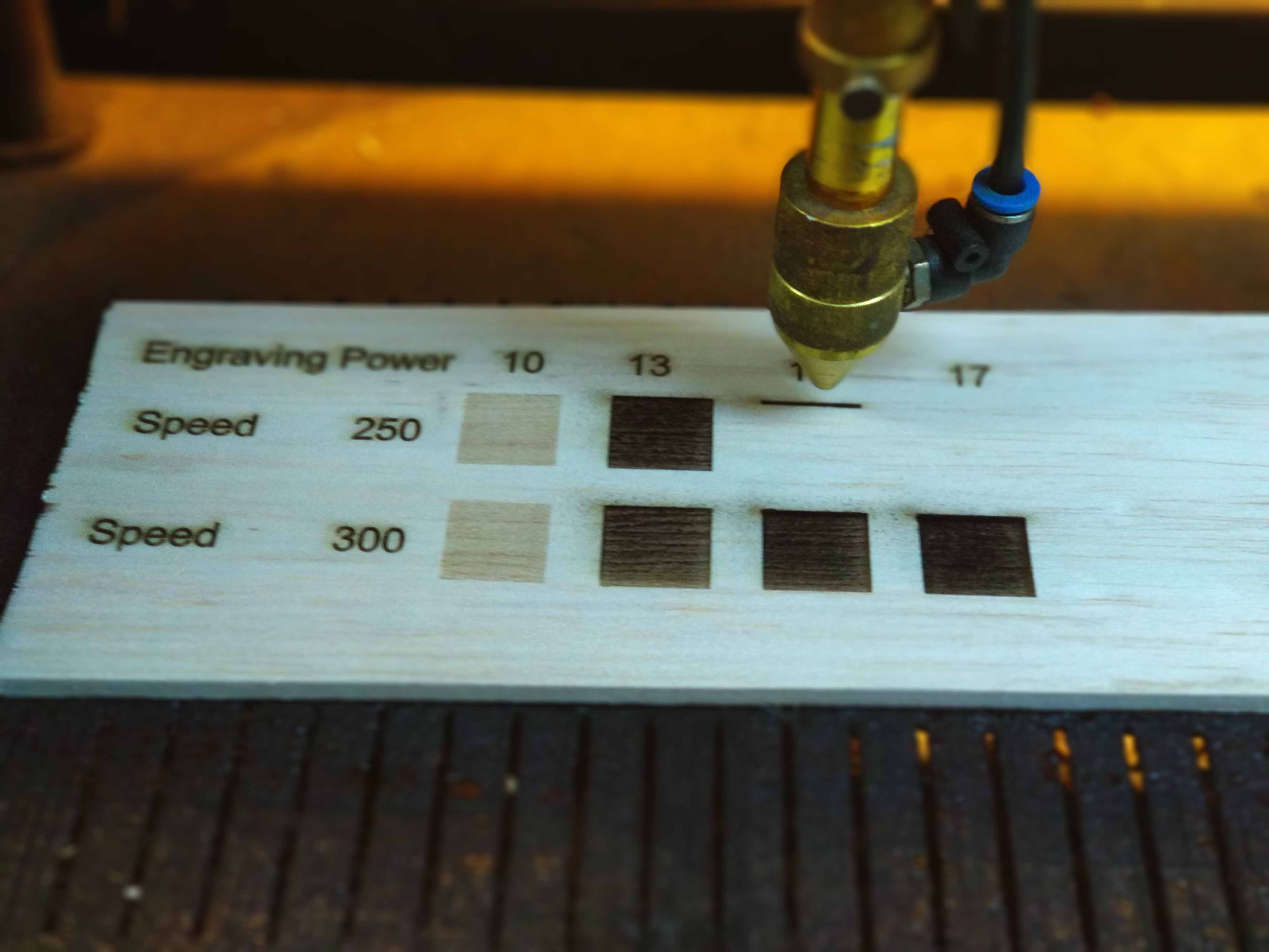
Balsa Wood Engrave test1, I had to stop the file because fire caught to the materials
Balsa wood engrave test2
Balsa wood engrave test2, I stopped it because it was about to catch fire
| Power | Speed | |
|---|---|---|
| Cut 3mm | 50 | 20 |
| Cut 5mm | 50 | 20 |
| Engrave for large details | 10 | 250 |
| Engrave for small details | 20 | 250 |
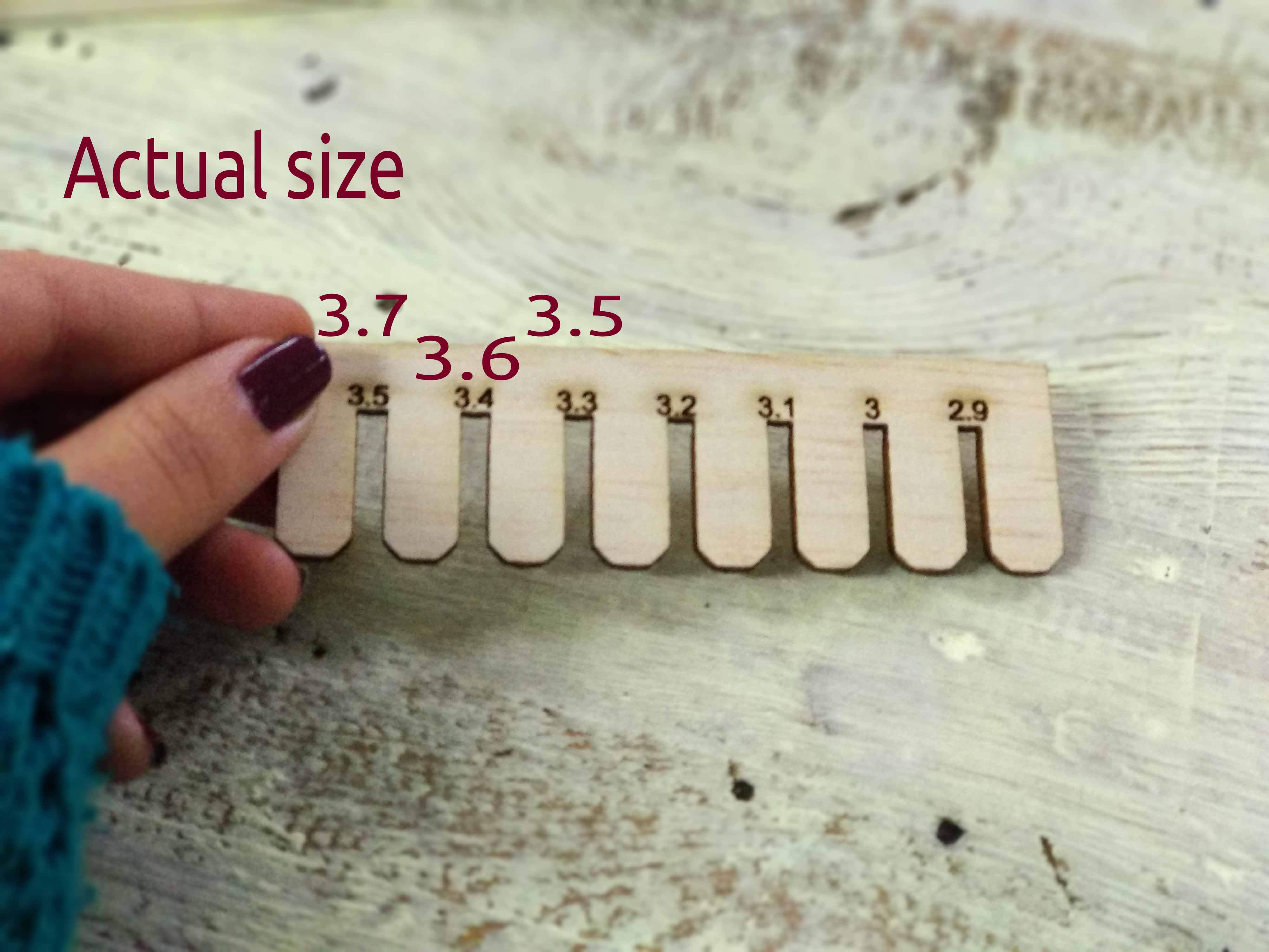
I used the comp test file designed by Haitham as part of the group assignment.The test file is a comp that has different size slots.
After cutting the comp with the values chose depending on the previous test, I measured the slot sizes it was 0.2 larger than the designed size.
Step2: Design and make press fit construction kit
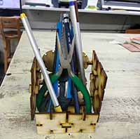
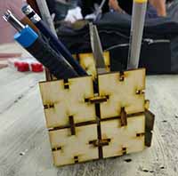
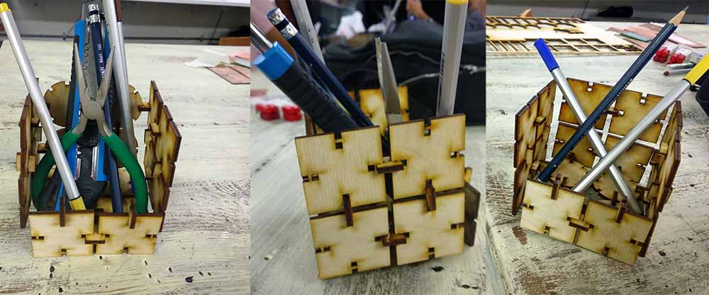
I decided to make a modular pen holder from 3mm Plywood which can be resized and its shape can reconfigured. I used fusion 360 for the design.
- Create Circular pattern
- Create 1st joint
- Adjusting kerf and making more joints
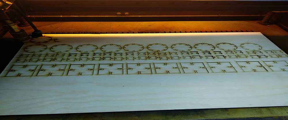
- Cut and assembel
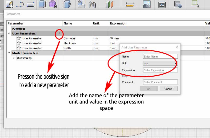
From Modify, Change parameters I added the parameters I need in my design
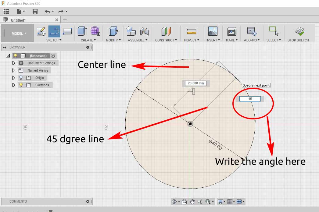
Create a new sketch and a circle, Then draw a center line and line with angle 45 degree
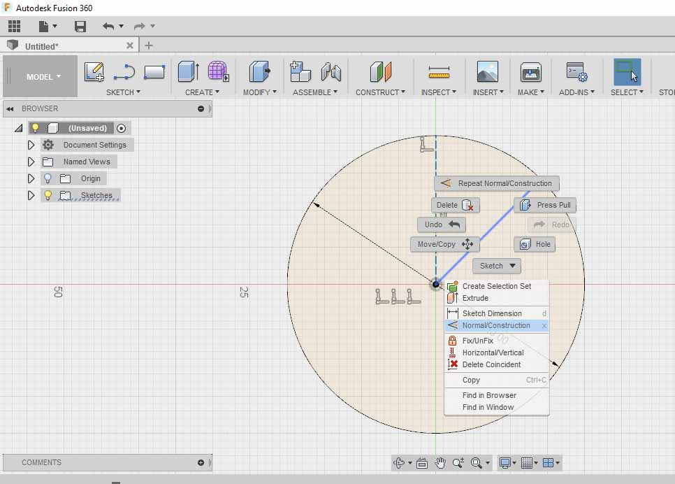
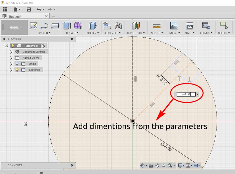
Righ click on any line and select normal construction to convert it into construction line
Drawing lines to form the slot and make all the dimensions related to the parameters added
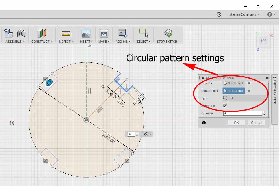
Select circular pattern from sketch, object refers to the pattern that needs to be repeated , select the center point to be the circle center then the quantity to be 4
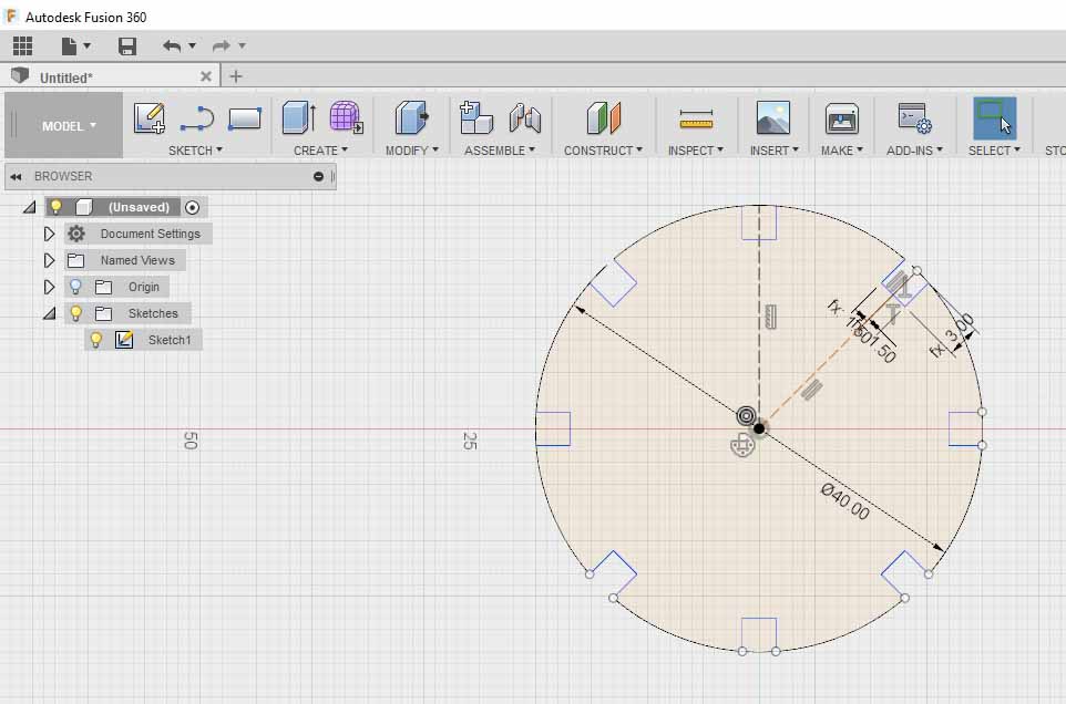
I noticed that the slot width should be with the material thickness so I adjusted it and made the pattern quantity 8 instead of 4 to have more varity
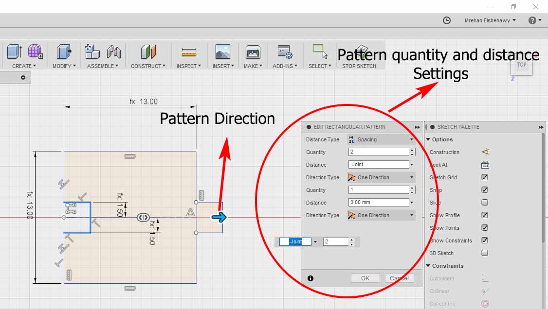
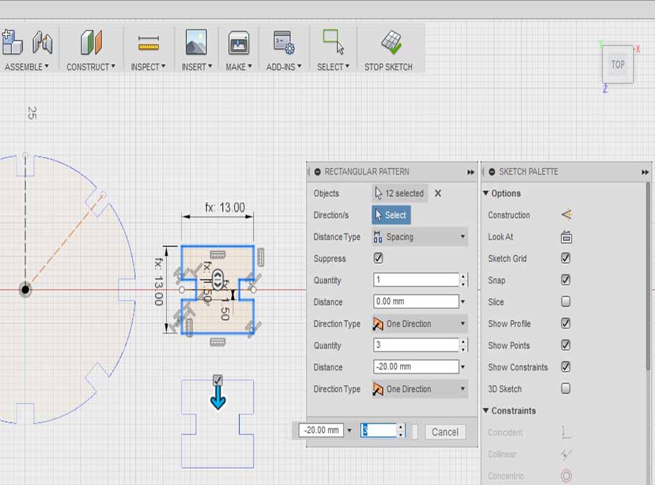
Creat a rectangle in a new sketch and make a slot on it with the material thickness.make a rectangular pattern from sketch, rectangular pattern then I made quantity two with distance equal to the paramete joint which is 13mm.
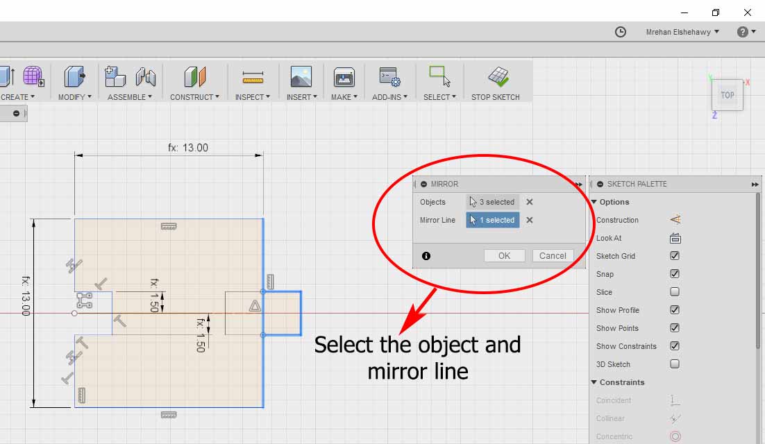
From create select mirror then select the object to be mirrored and the mirror line
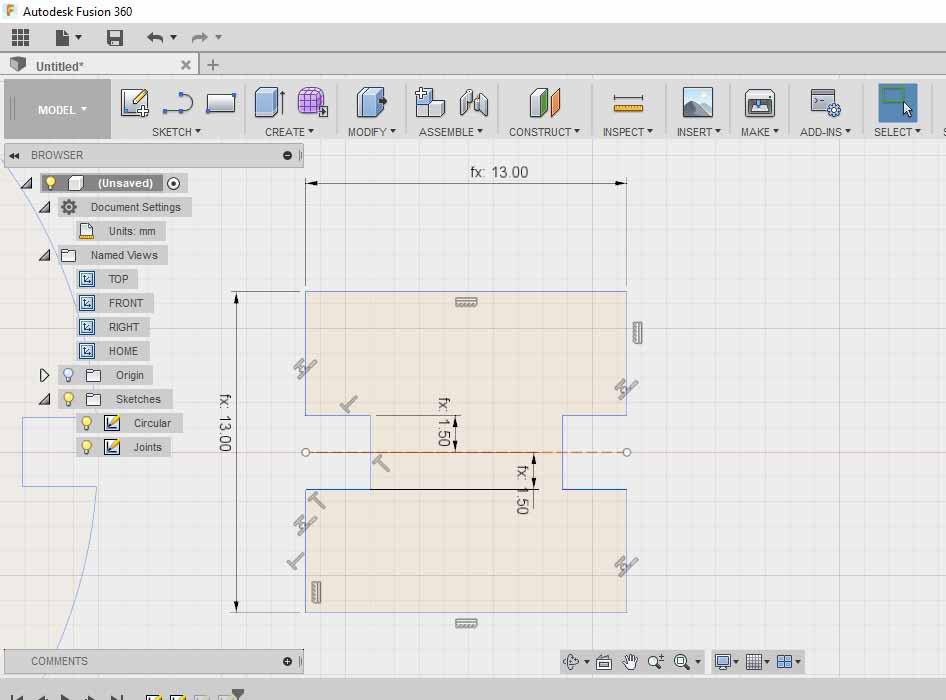
this is the result after applying the mirror step.
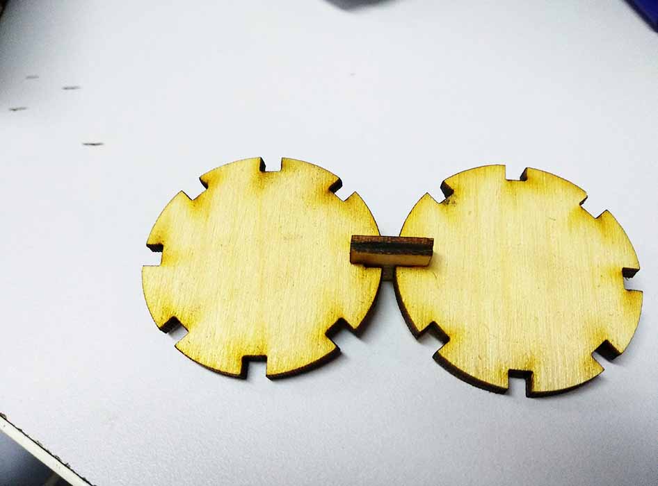
I tried to cut and fit these two parts but I realized that I forgot to adjust the kerf!
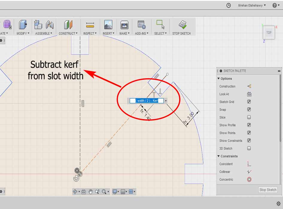
Subtract 2*kerf from the slot width so for half of the width it will be (width/2)_kerf
Duplicate the joint through the rectangular pattern tool
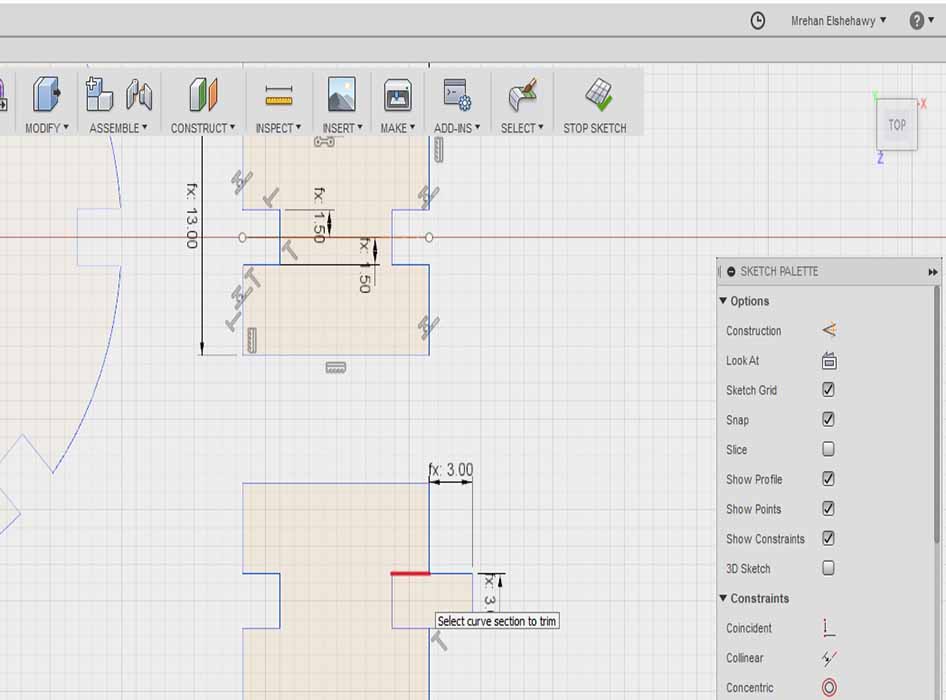
create a nothch on the second joint
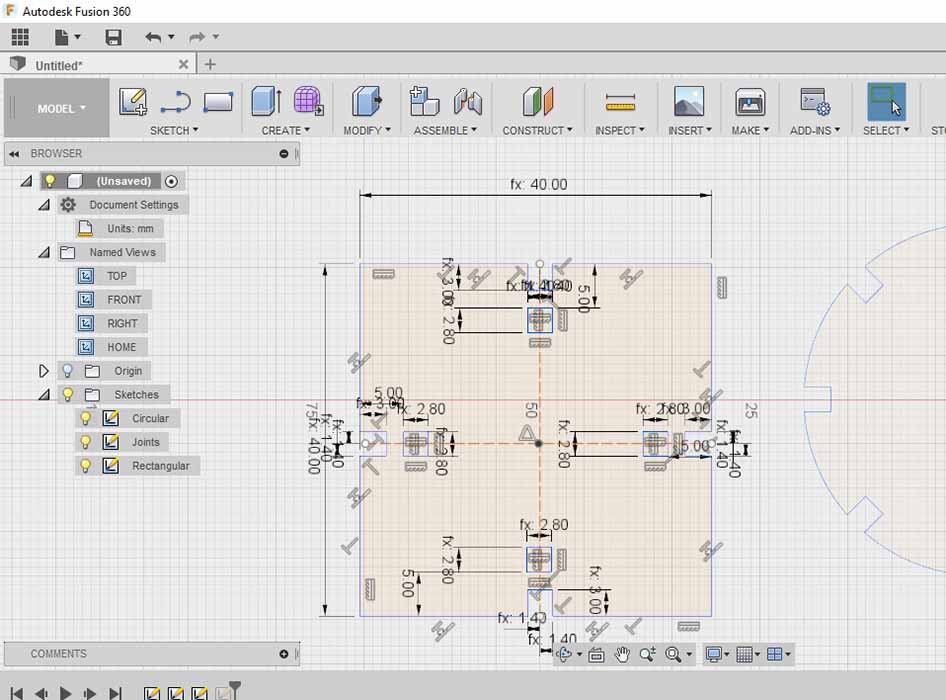
Make a rectangular pattern
Step3: Cut Something on Viynl cutter
It's my first timt to use the viynl cutter so I decided to cut my startup logo "Cool Stuff" .
- Prepare the design on the software
- Cut the Design
The software used in our Fab Lab is cut studio. The files that can be opened by cutstudio is images and AI files
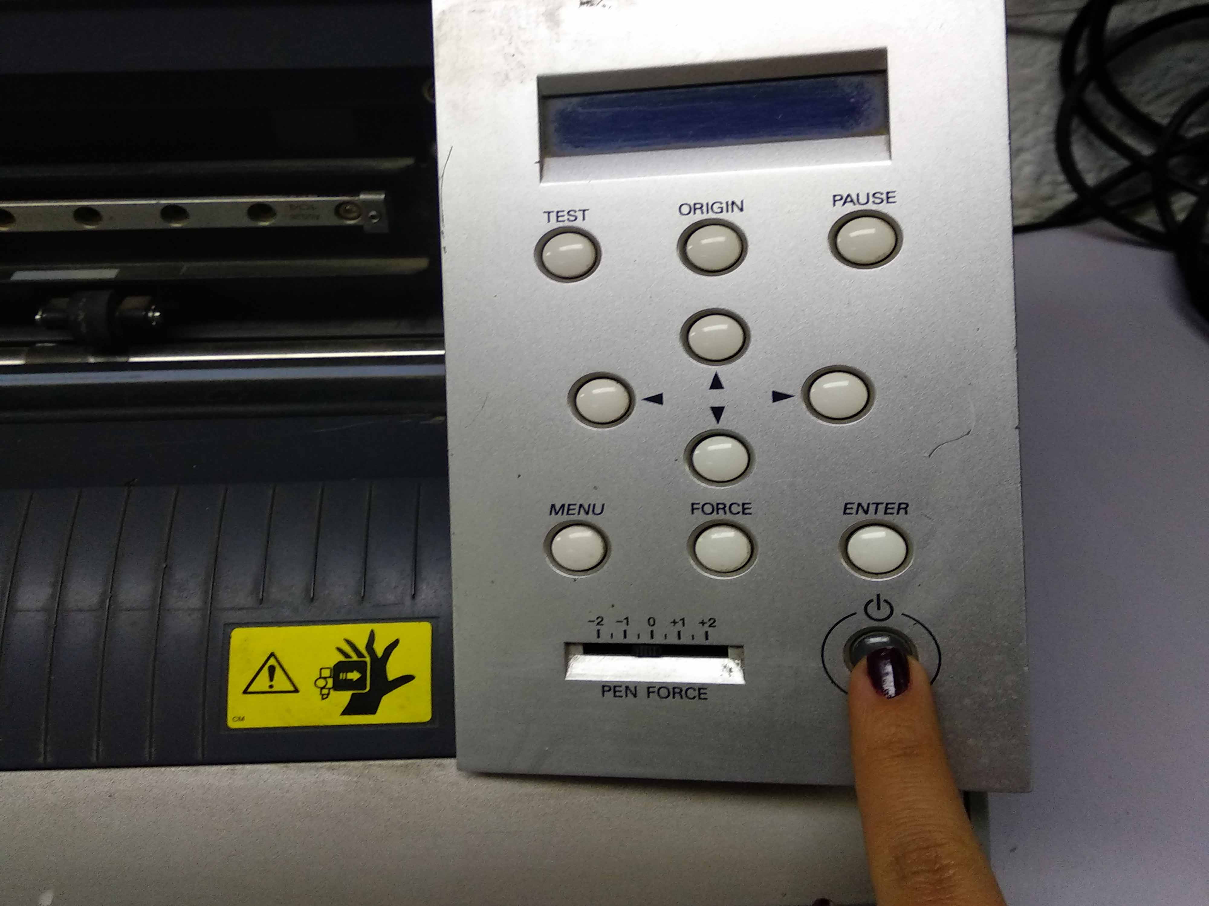
Switch on the machine and load the viynl piece
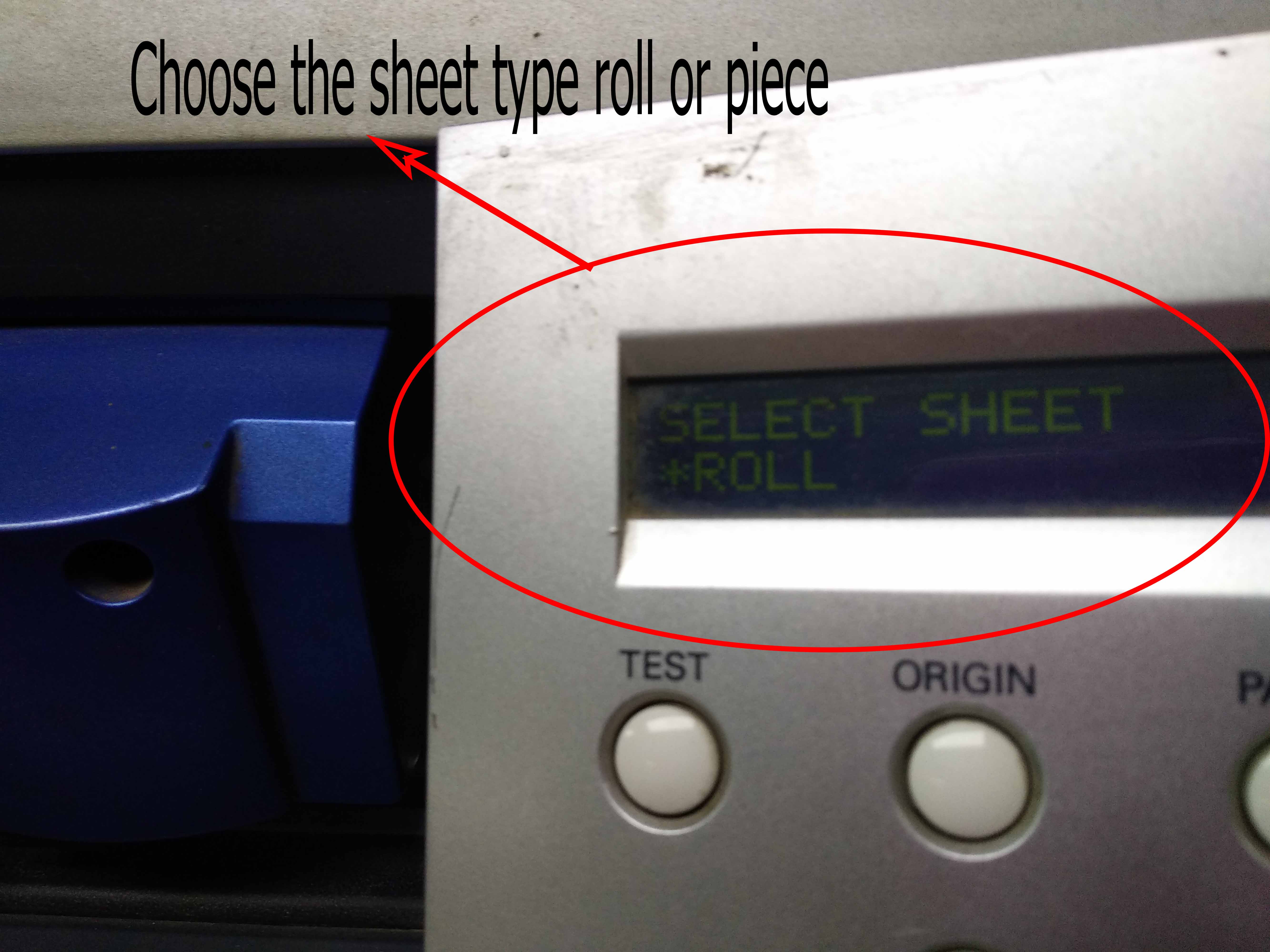
After swiching on we have options to measure the viynl piece we have . roll to measure the width only and piece to measure the width and length
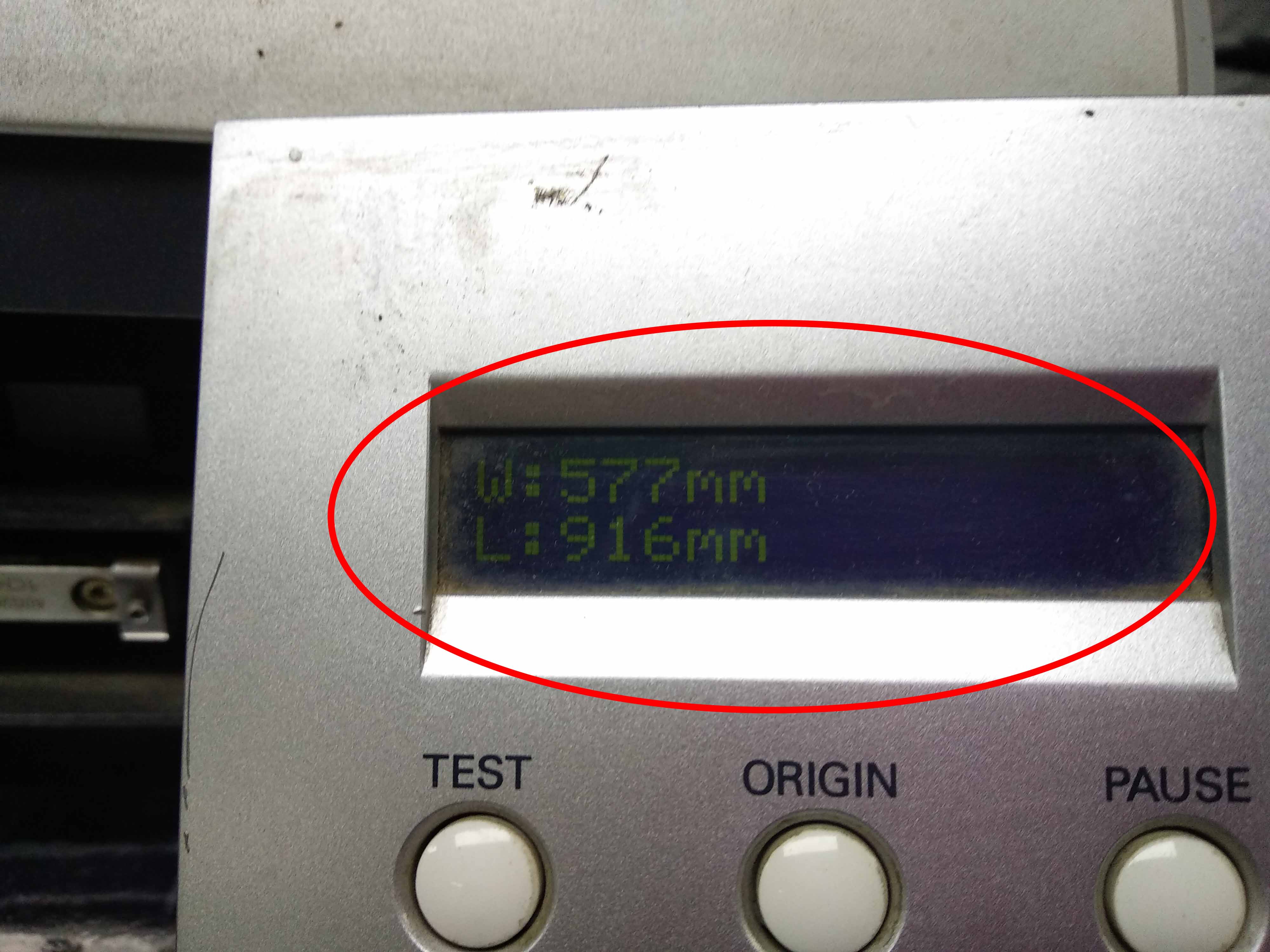
I chose piece then the machine started to measure the viynle piece dimensions and then it showed the dimensions on the screen
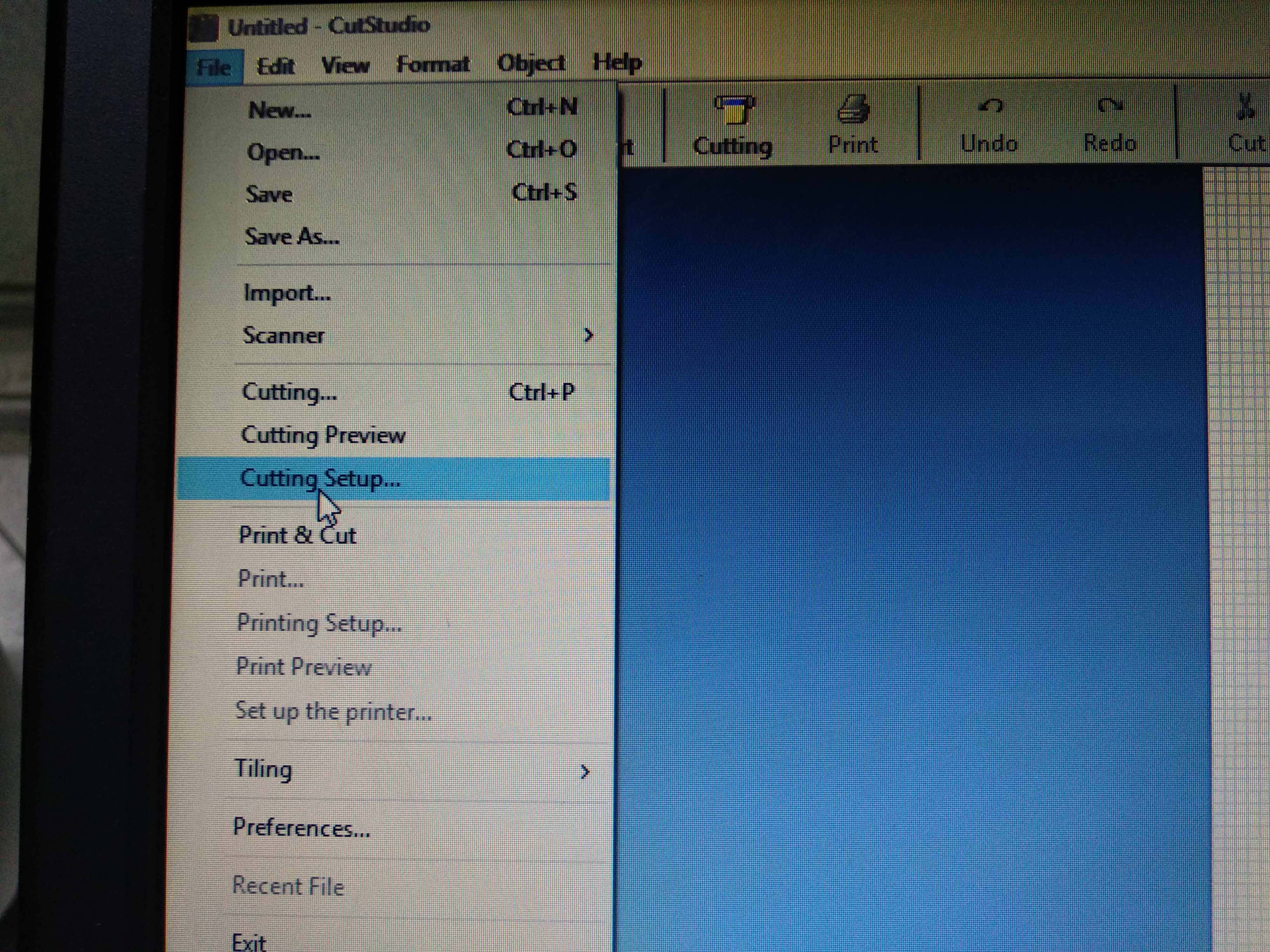
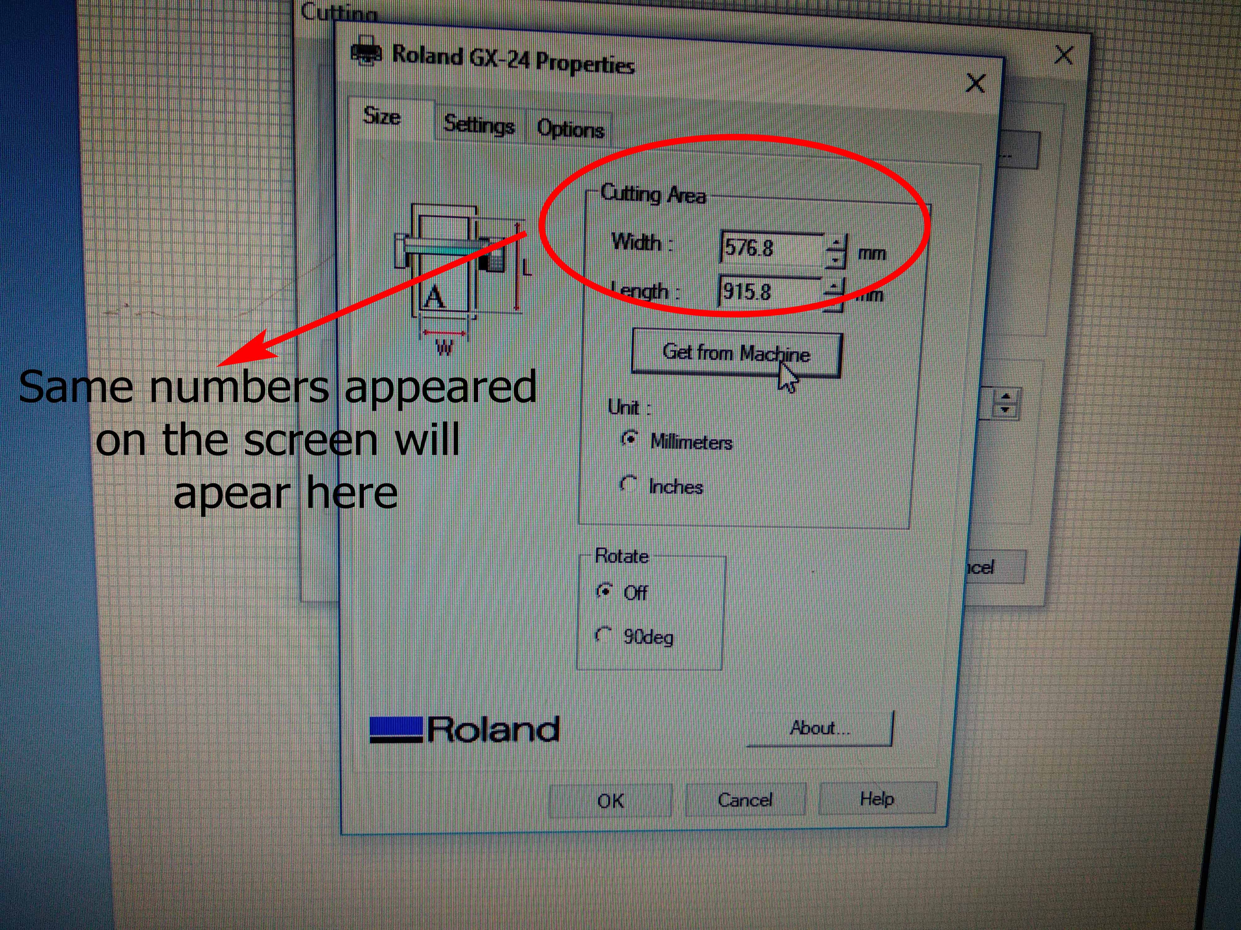
Click file and cut properties to adjust the cutstudio working area according to the size of the viynl piece I had
Slect get from machine so the software will get the piece area that the machines measured
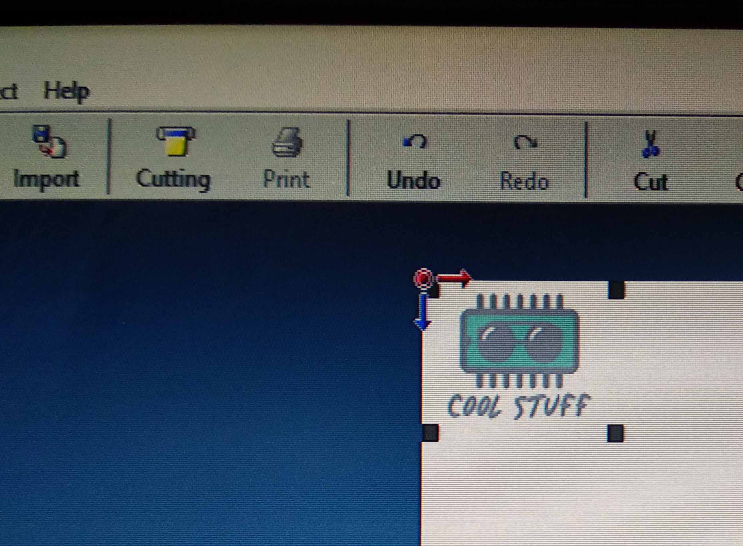
Click file, import and chose my image. Right click on the image and selet properties to change the size of it.
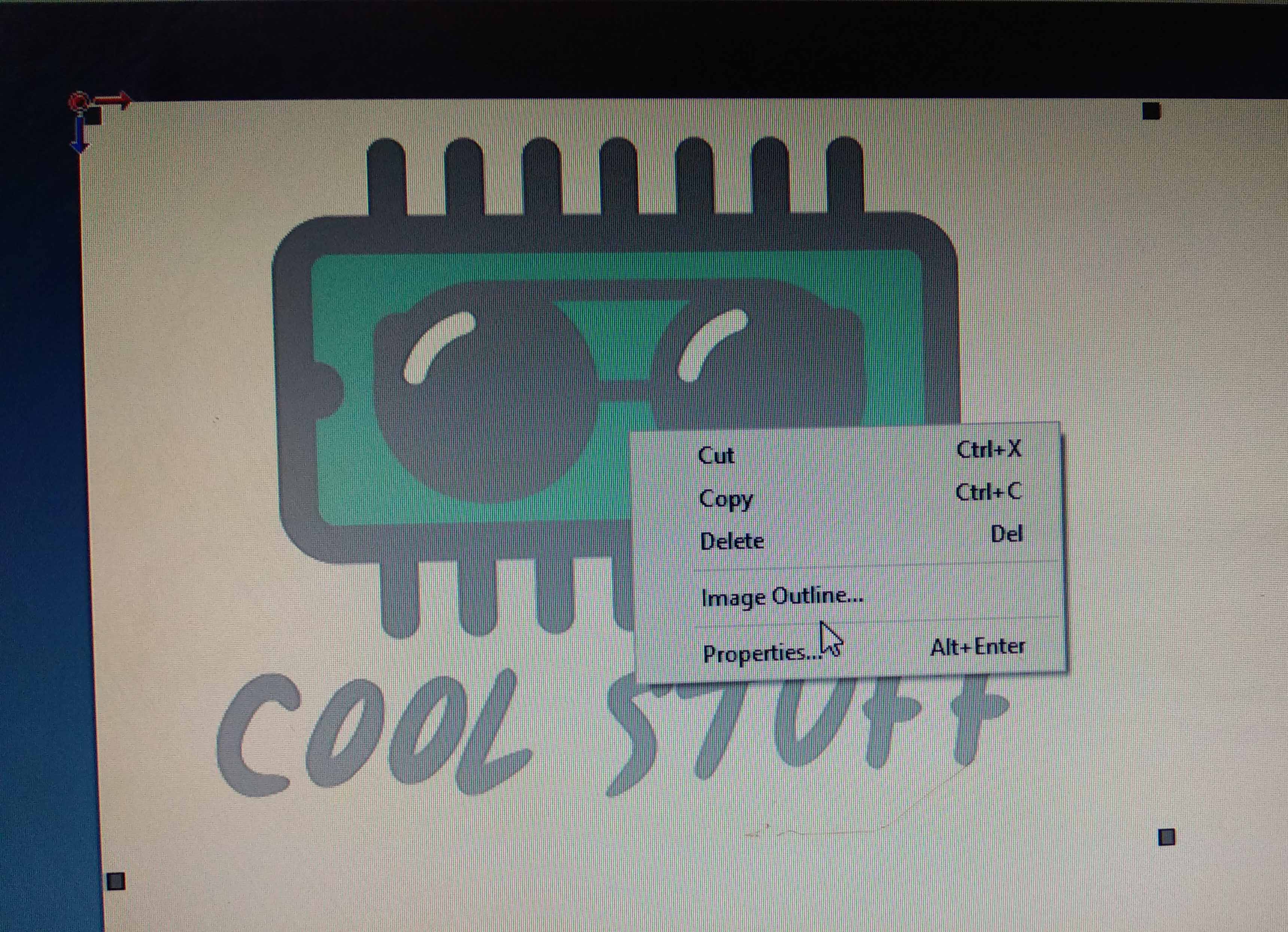
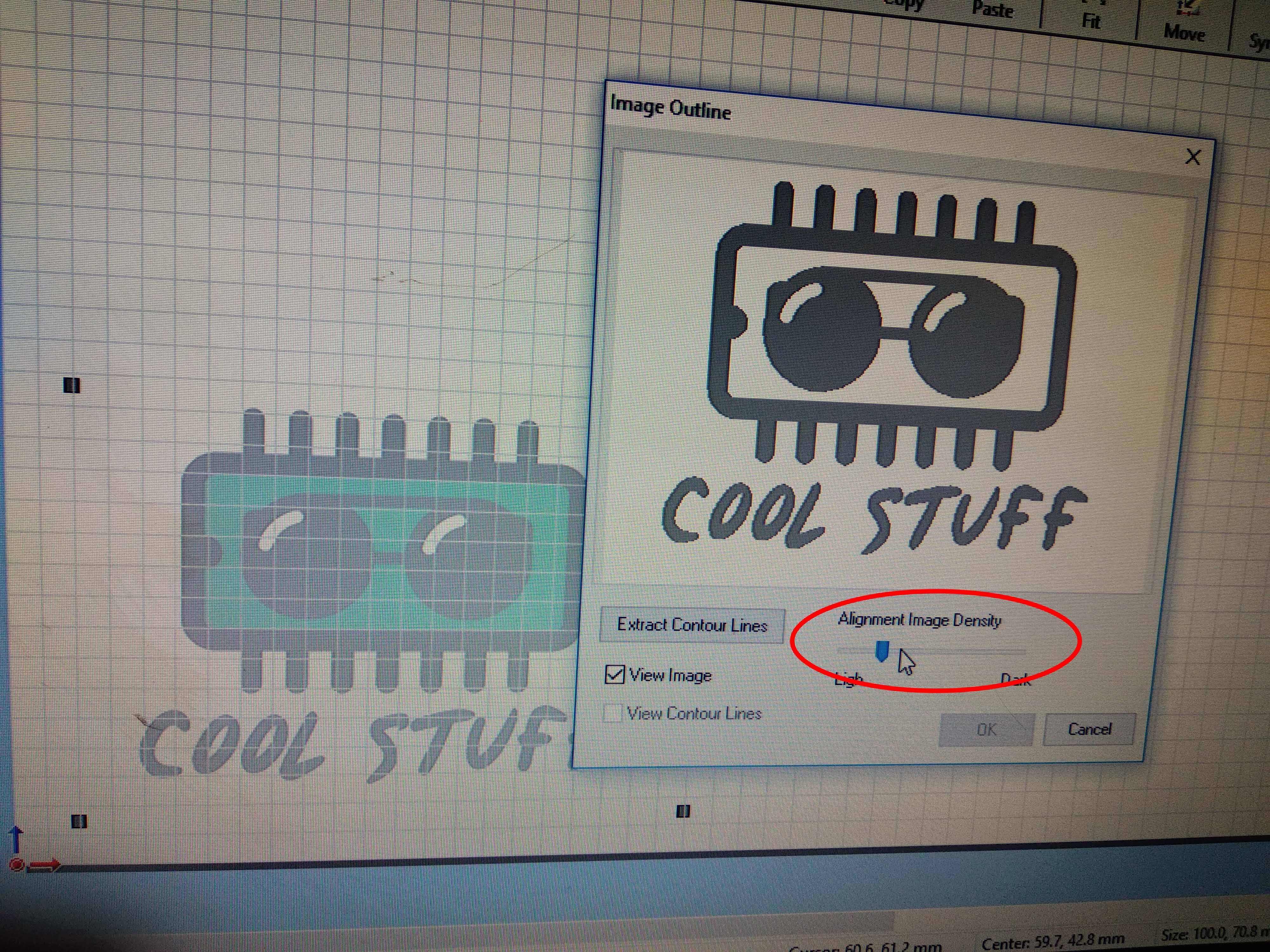
Cutstudio only cuts lines so Right click on the image and select
Change the image density untill having the proper image
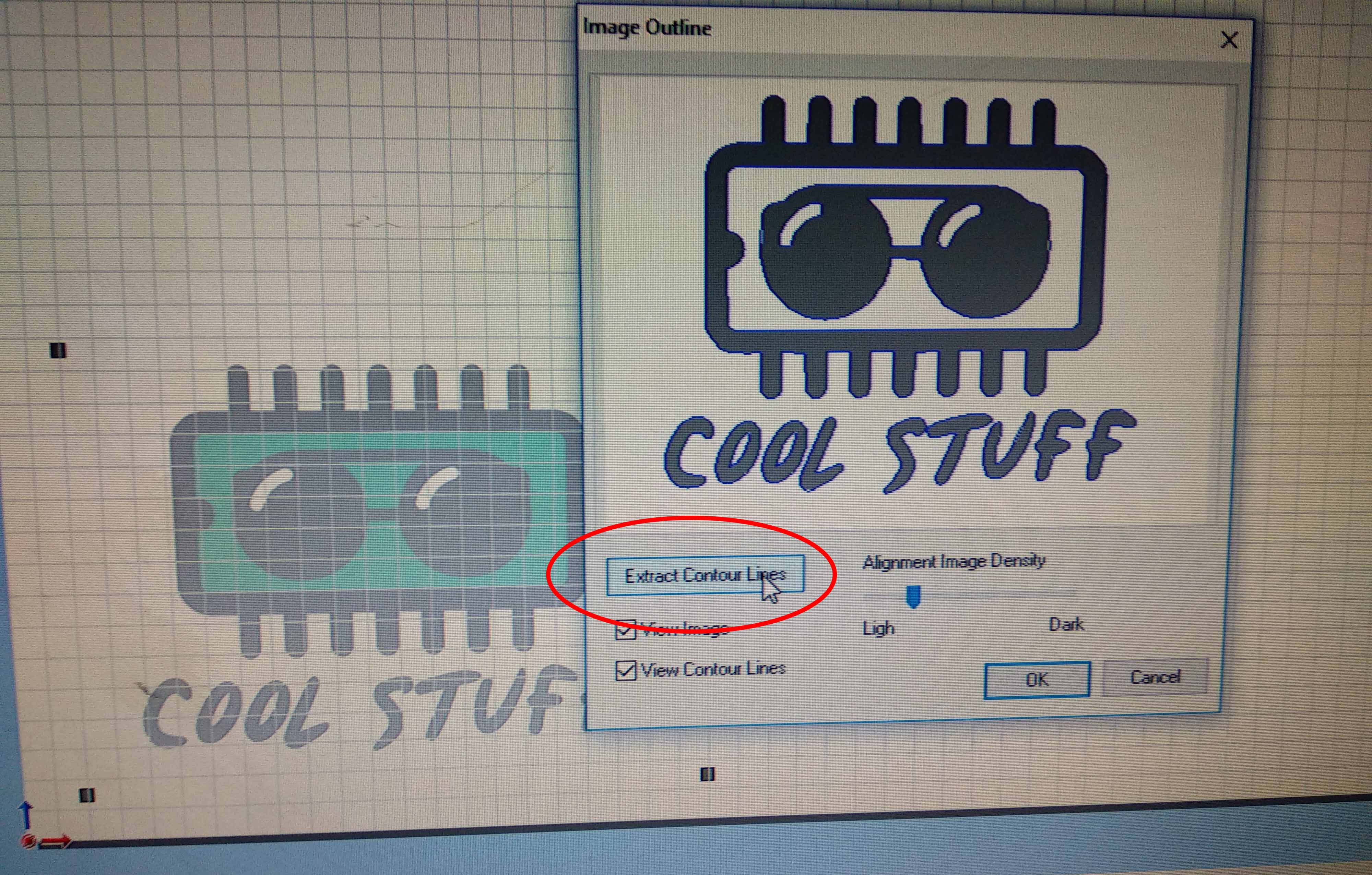
After adjusting the image density, click extract contour lines
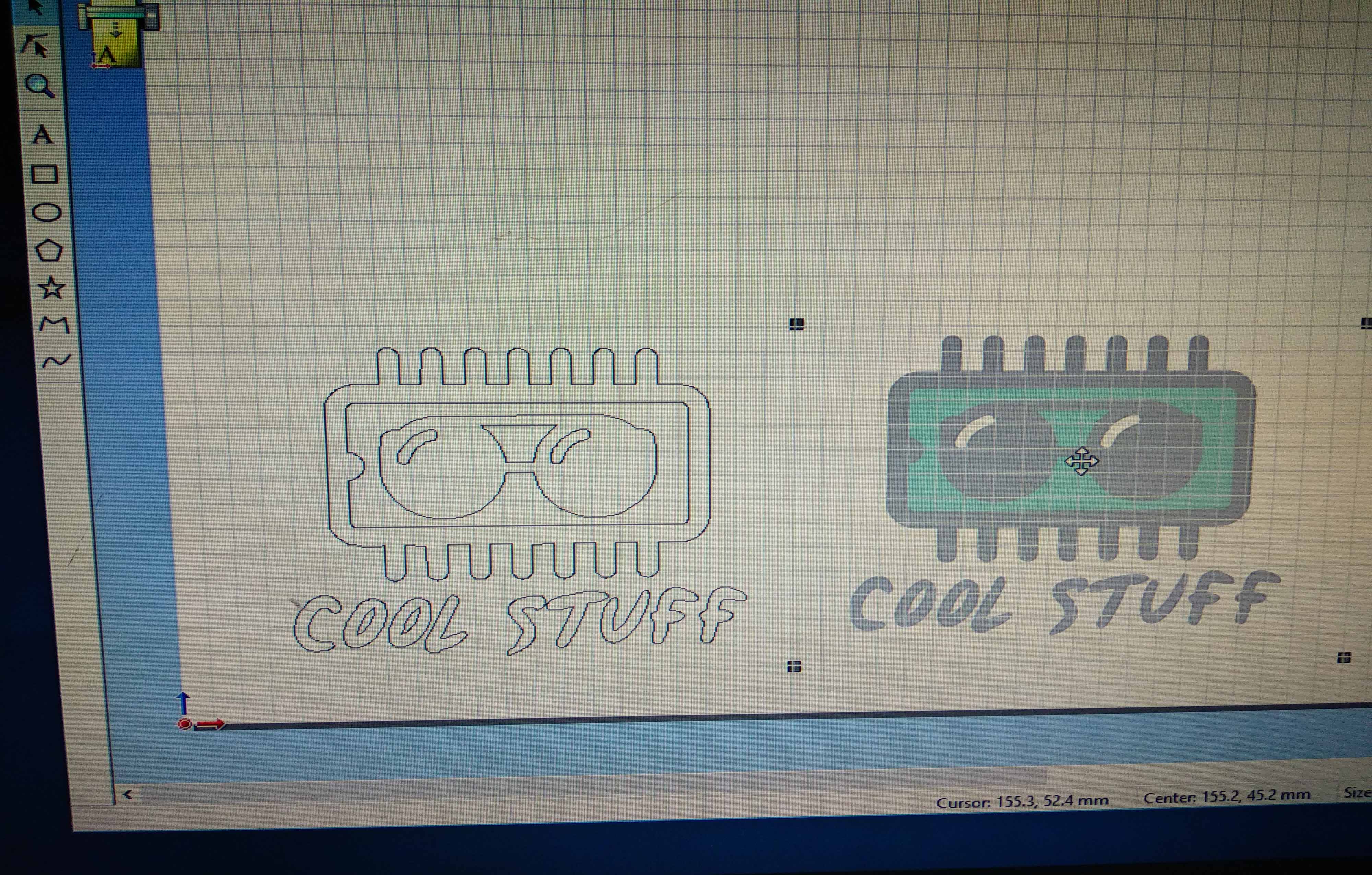
I had the image and the outline
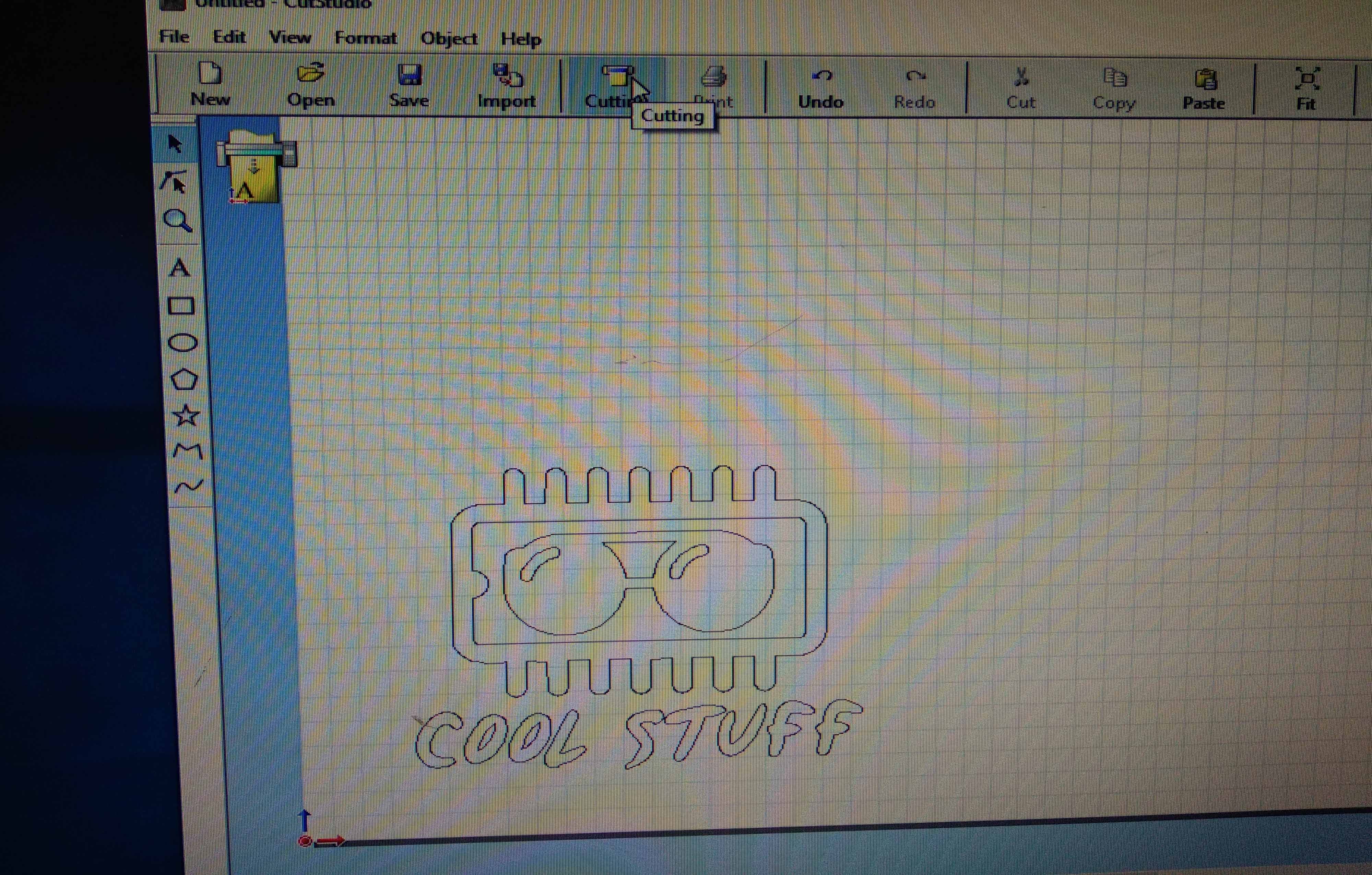
I deleted the image and left the outline to be cut
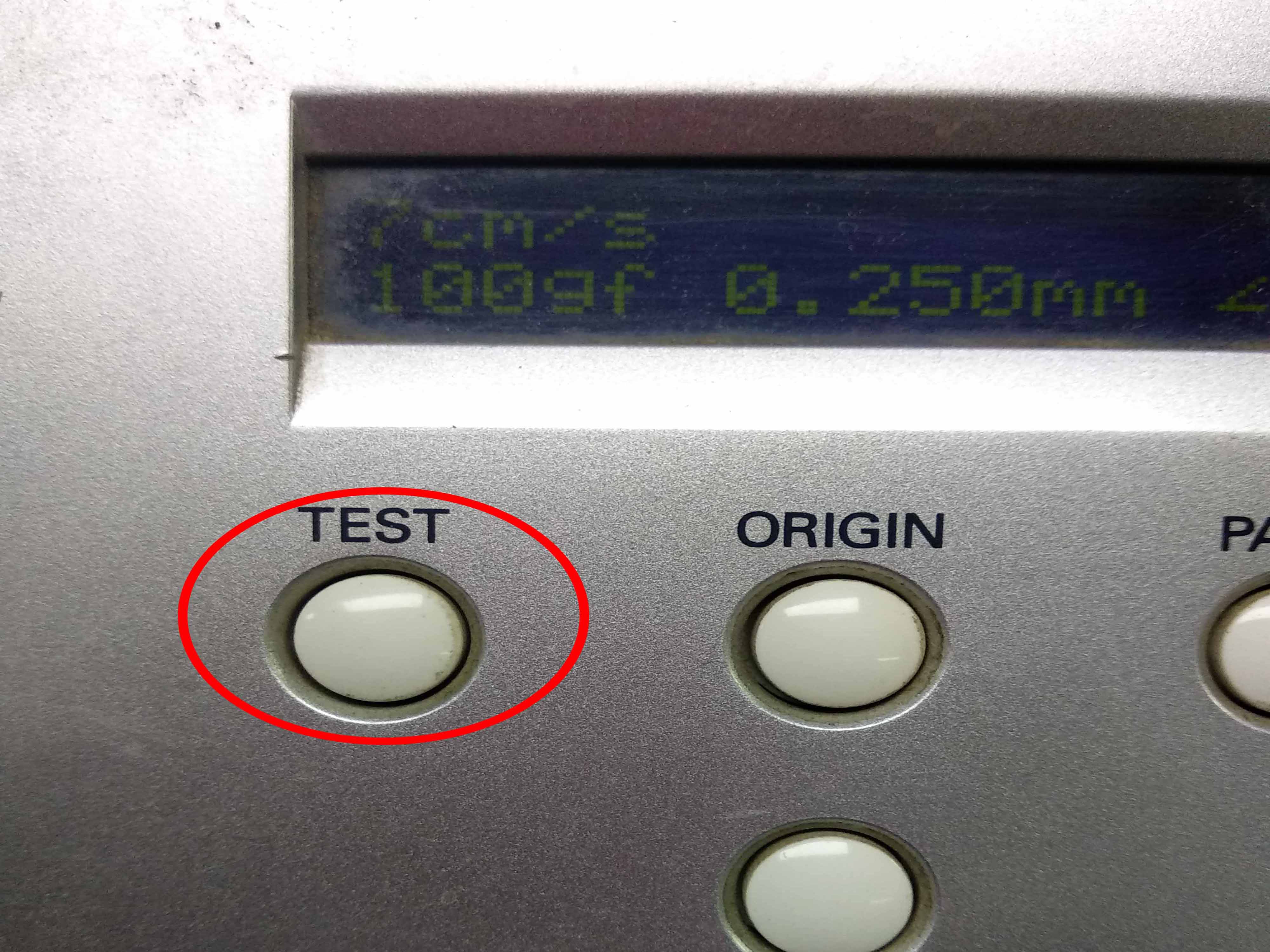
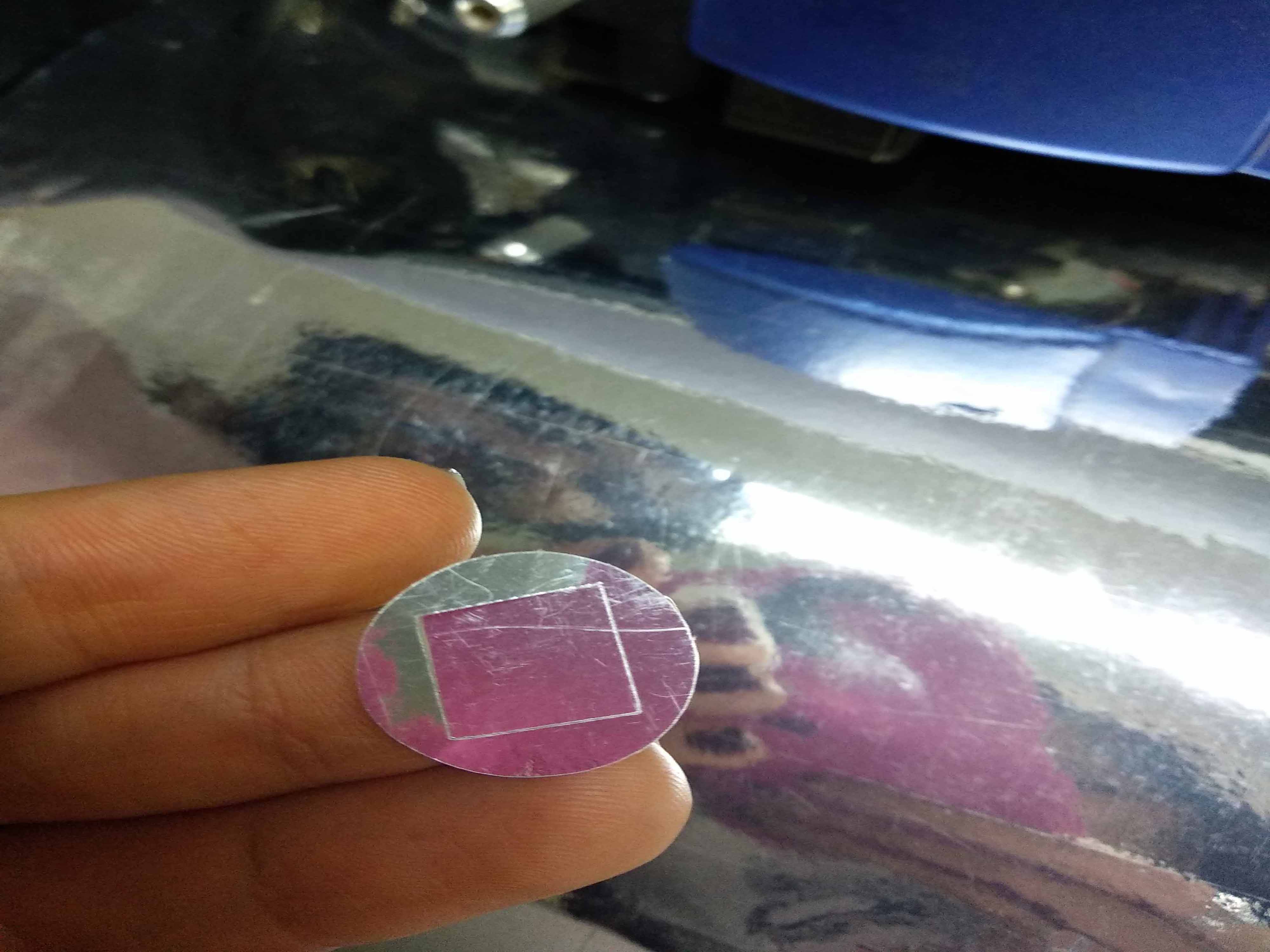
Press test to cut a test file and check if the viynl cutter is working well
a square and a circle inside it will be cut
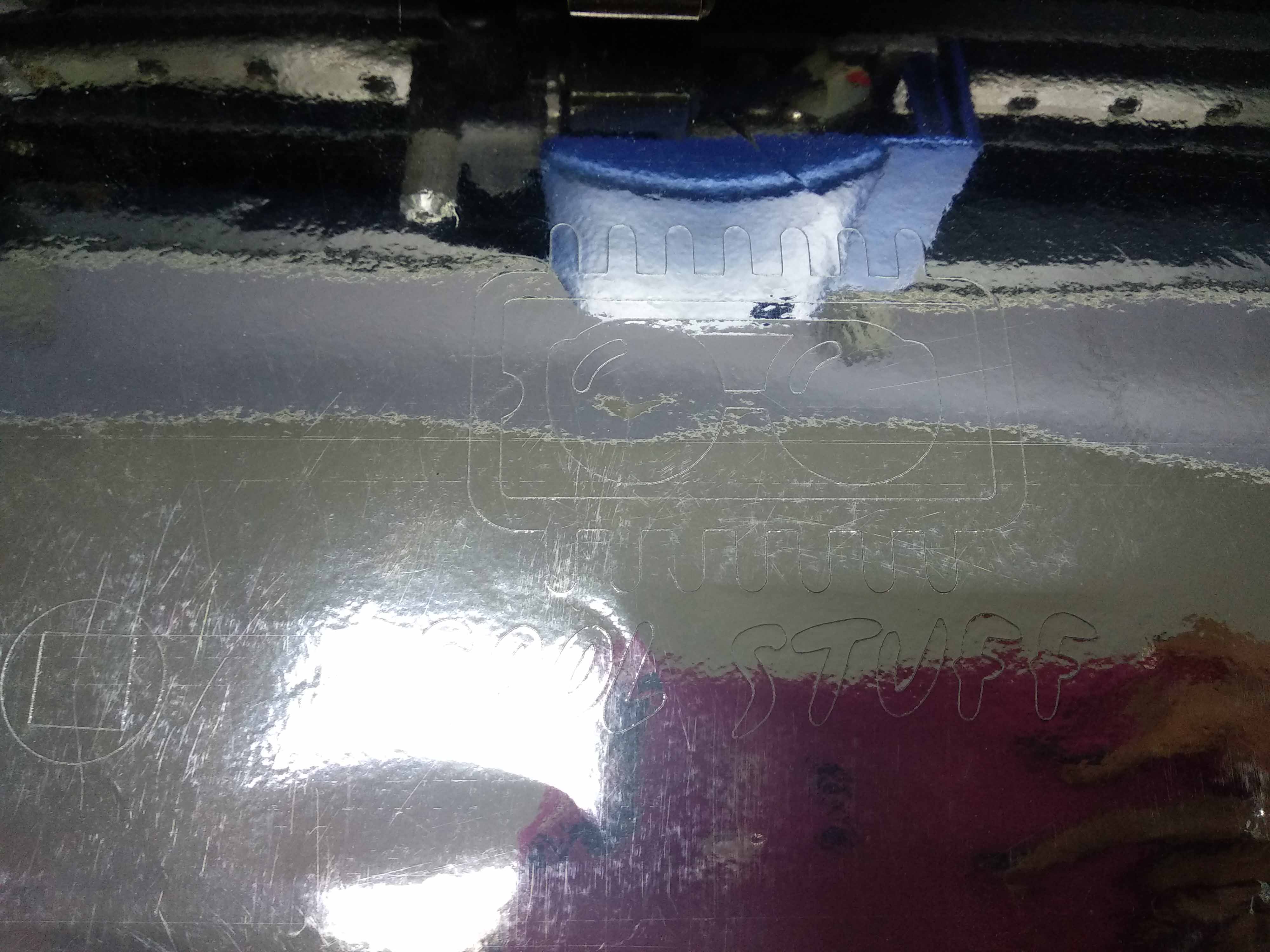
After making sure that the machine is working press cut in the software to cut the design
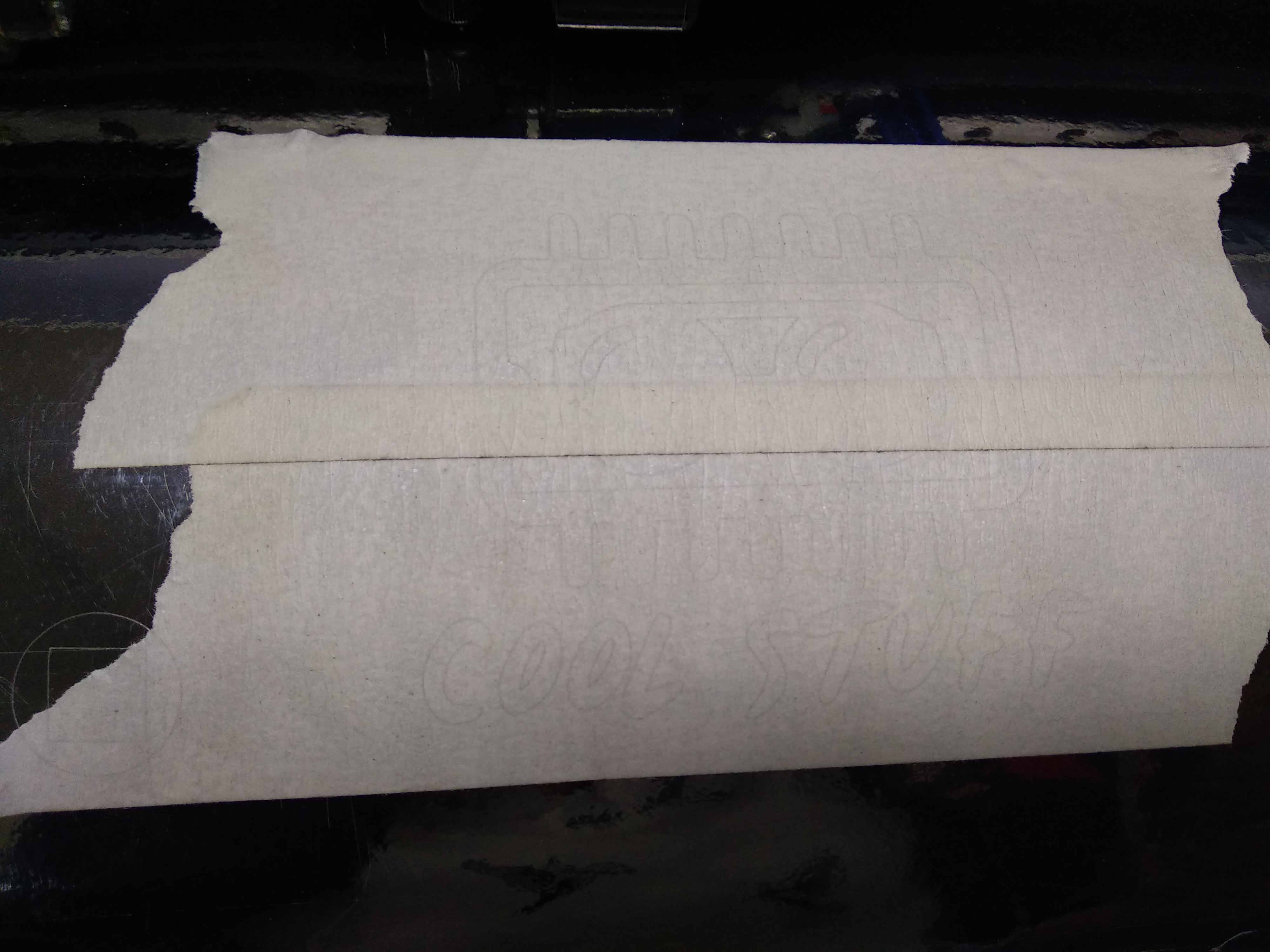
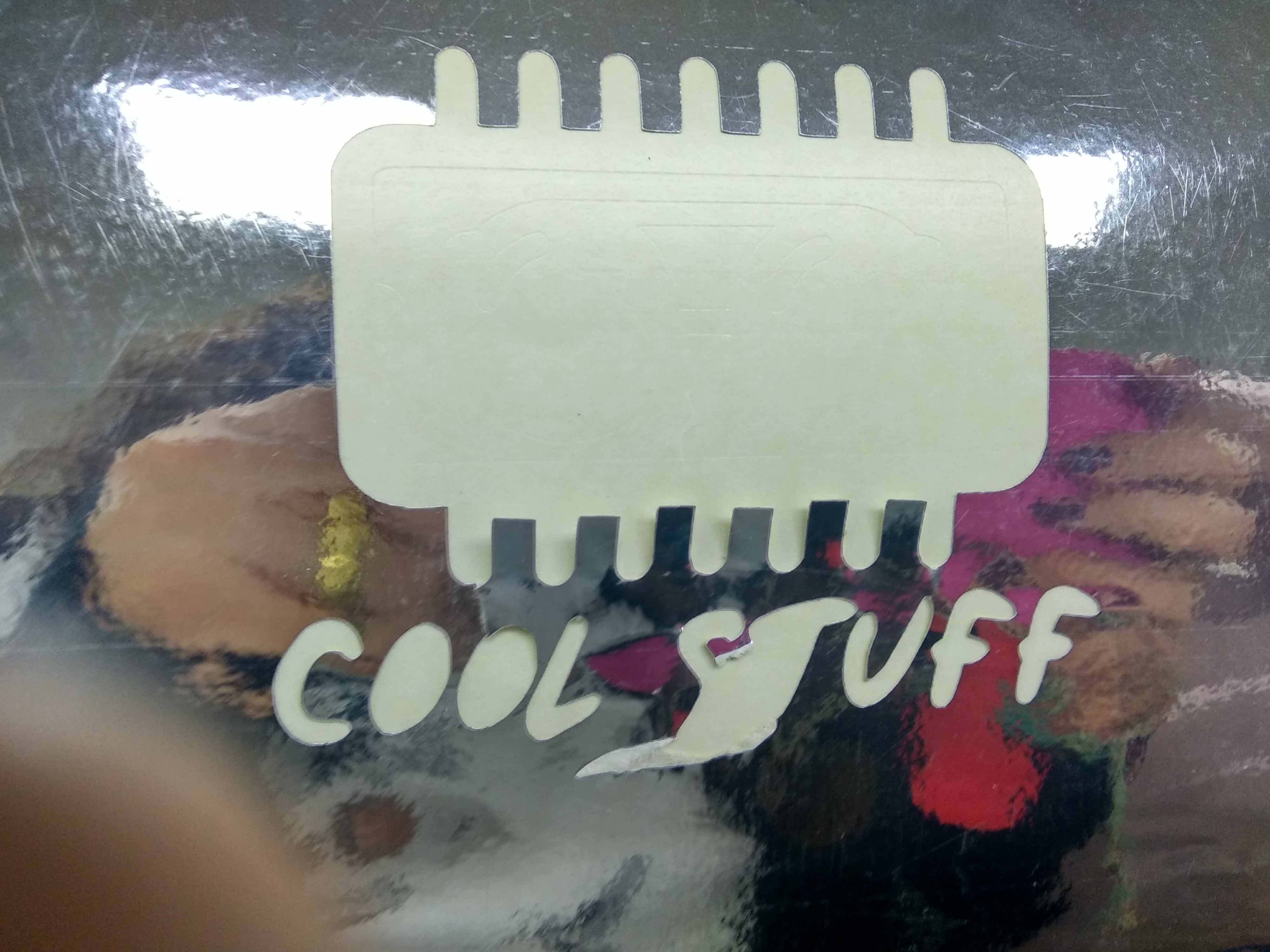
I placed a tape on the cut design to make it easy to remove it from the viynl sheet
I removed the tape with the design on it
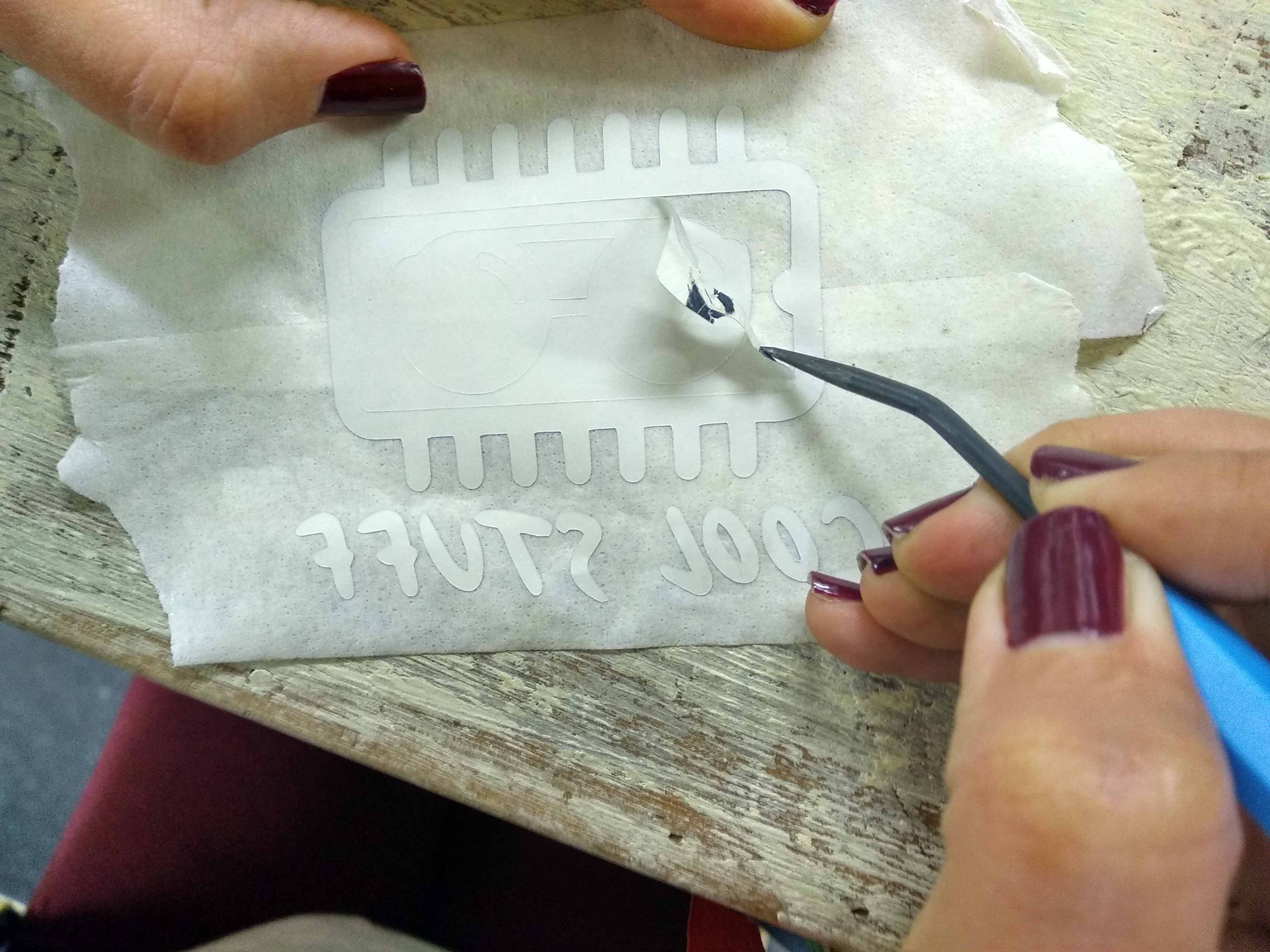
After that I used this tool to remove uncessary parts from the design
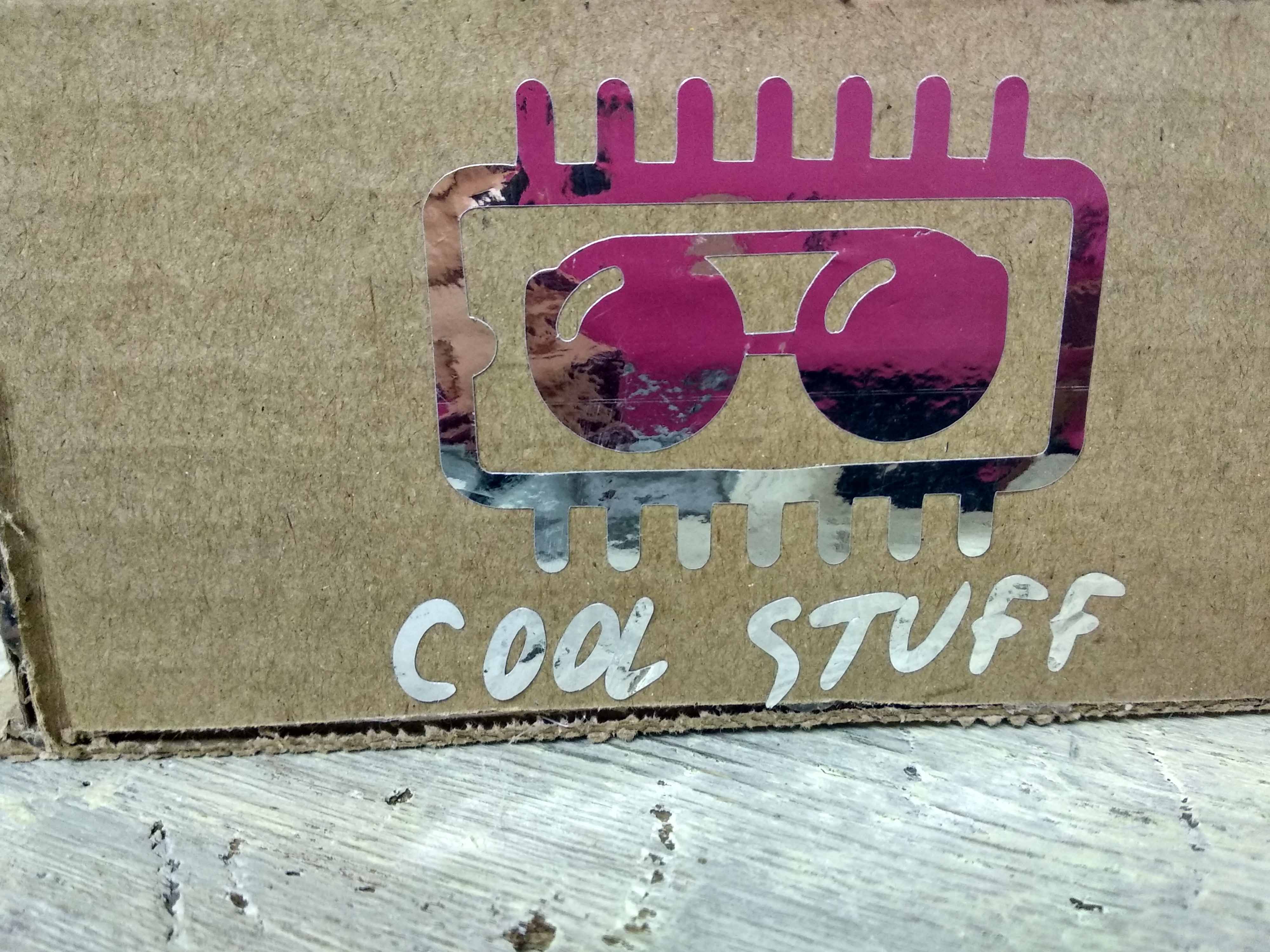
Then Stick it to the desired place. I put it on card board but noticed that it didn't stick well on it so I don't recommend using card board with stickers
Files:
- Press fit construction kit design on fusion 360
- Circular pattern.DXF
- Rectangular pattern.DXF
- Joints.DXF