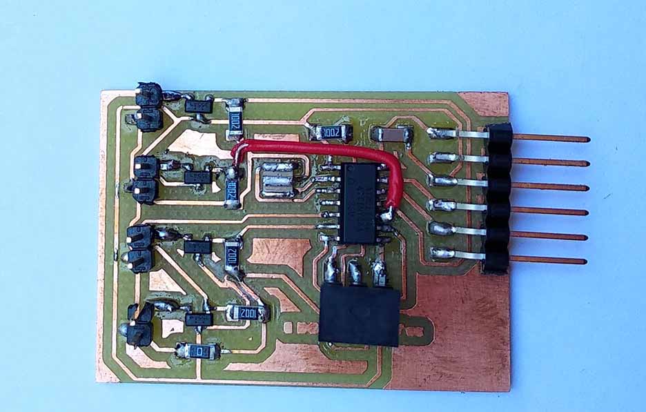
Output devices

This week's tasks are:
- add an output device to a microcontroller board and program it to do something.
- Describe design,fabrication process and the program
For this assignment I decided to deign and fabricate aLeds circuit that can be controlled as a one unit to be on or off.
* All datasheets, files and online refrences are attached at the end of the page.
Step1:Think about the circuit
I need the unit to have 5 leds and after searching the internet each LED takes a current of 25 mA. So the required current for only one set is :
$$I_{req} = {25 \times 5} = 125 mA$$Fromt the Attiny44 datasheet, The maximum current per any pin is only 40 mA.This means that the led set can't be connected to the attiny directly. Also I can't connect every LED to a pin as I need multiple LED sets to be connected. This transistor is n channel and it means it got triggered when a positive voltage is applied to its gate.
I though of using transistor as a bridge between the controller and the LEDs.
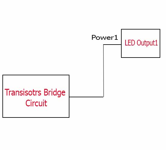
circuit block diagrame.
Mosfet transistor NDS355AN ratinings.
The idea is when the transistor receives a signal on its gate from the microcontroller it connects the power source directly to the LEDS circuit and the required current will not pass through the attiny44 and the whole current will pass through the transistor.
The transistor we have in the inventory is NDS355AN MOSFET power transistor and from the datasheet it can withstand a current of 1.7A which is very sufficient for the LED unit.
I though of using transistor as a bridge between the controller and the LEDs.
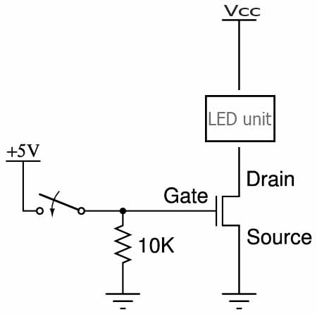
The basic connection of n-channel mosfet transistor.
Step2:The transistor bridge circuit
- I draw the circuit schematic and board using Eagle software.Detailed instructions on how to use Eagle to draw schematic, board and generate requied files for milling visit Electronics production and Electronics design documentation. The design is made for four LEDS units
- Fab Library
- pin header2 library
- 2 pin header: PINHD-1X02_2.54-SMD
- Capacitor: CAP-US1206FAB
- Resistor: RES-US1206FAB
- Attiny44: ATTINY44-SSU
- Resonator: RESONATOR
- FTDI headers: FTDI-SMD-HEADER
- ISP pin headers: AVRISPSMD
- The 10k resistors connected between the transistor gate and the ground are used as pull down resistors to ensure that the voltage value at the gate is zero while ther is no output from the micocontroller.
- The 0 ohm resistance is used as a jumper wire( will be explained more in the next step).
- Each transistor delivers the power to different LED unit.
- switched to board mode and made the layout of the PCB
- milling, soldering and testing
- Test the functionaltiy of the circuit
The libraries required for this design:
*all libraries are attached at the end of the page.
The components I used with their names in Eagle:
The schematic of the transistors bridge circuit.
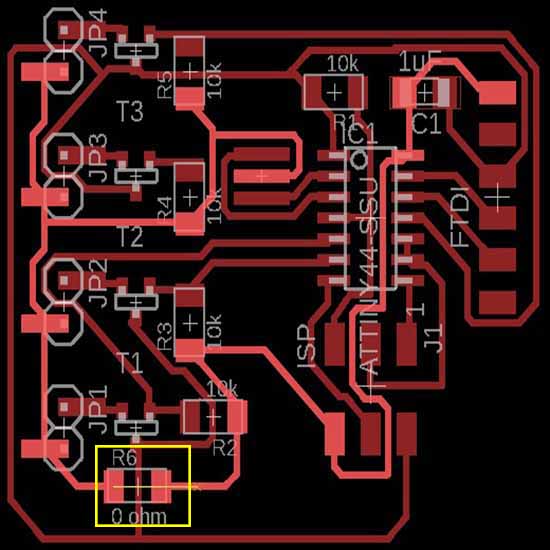
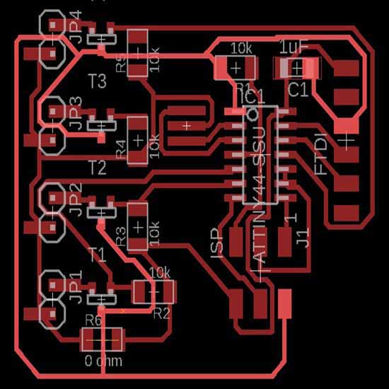
All the ground shoud be connected to each other and it was hard to do it so I added a 0 ohm resistance.
All Vcc lines are connected to eachother without any jumpers.
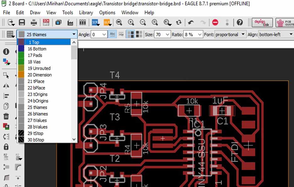
I decided to write labels on FTDI pinheaders to show where I should connect Vcc,GND,Rx and Tx for easier connection.
I selected the text to be on the top layer to apear on the milling photos
After writing all the text I needed I checked the Design rules.
Width error appeared because of the text.
When selecting the info tool and press on the text settings will appear.
when changing the ratio to 30% the error has been solved.
The ration on eagle text means the width of the line. As the design rules is set to minimum 16 mil so the ratio should be increased to be more than this value or equal to it.
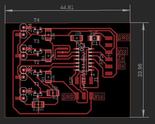
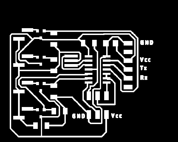

The final board with total dimensions of 4.5 x3.5 Cm.
The traces file for milling.
The outline file for cutting.
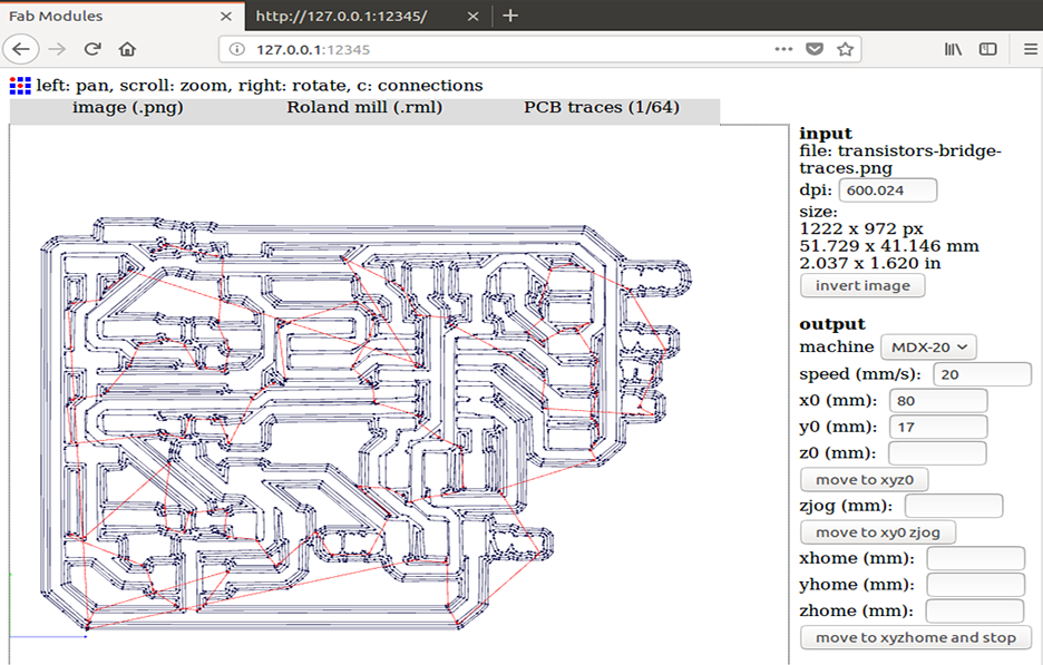
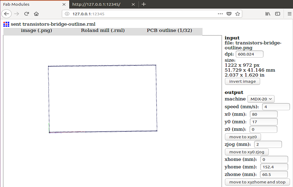
Prepare milling and cutting files using fab modules and do the milling on roland MDX-20 milling machine
For more detailed instructions on how to use fab modules for PCB milling check Electronics production week documentation.
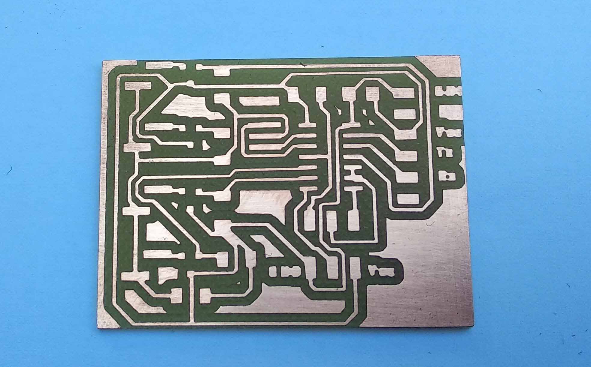
The milling result.
Before starting the soldering I always check the PCB with Avometer and the buzzer tool for short circuits or unconnected wires.
For this circuit I found three errors.
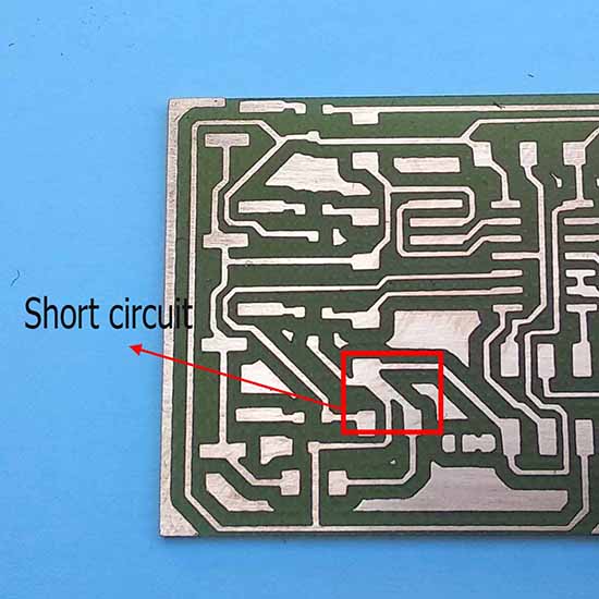
connected wires
These wires are not supposed to be connected on the schematic.
I found a short circuit where two wires are connected and they are not supposed to be. I fixed the error using utility knife.
pin 9 and 10 are connected to each other and no pin is connected to R4.
connected wires should have the green point indication, if not exist it means that it's not connected.
I also found that pin 9 and 10 are short circuited while they were not supposed to be connected. pin 10 was supposed to be connected to R4 and the transistor to give it the signal but it was not! Actually this issue was because of my design.In eagle schematic if the green wires that connect the components to each other are not have that little green circle on intersections, it means that they are not connected and the wires are just passing over eachother. This is what happened to me as shown in the photo above.
I solved the shortcircuit issue with the utility knife and connected pin 10 to R4 using a jumper wire.
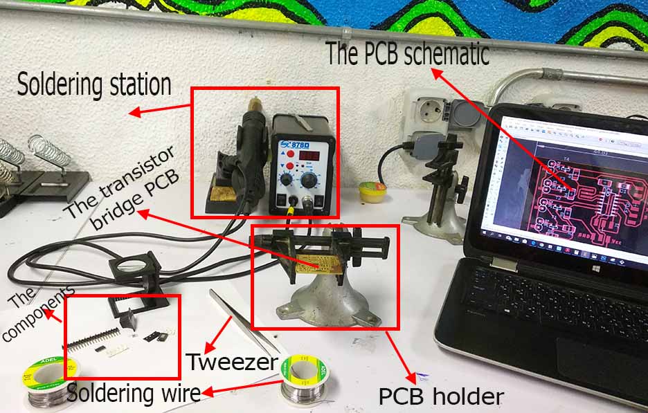

After finishing all the errors prepare the tools and start soldering.
Final transistor bridge PCB result.
I wrote a simple Arduino code to trigger all the transistors gate and check if the Vcc was successfully deliverd to the output pins.
For detaile instructions about how to upload a code on Attiny44 microcontroller check Electronics design week documentation and Embedded programming week documentation.

Get the arduino pins equivilant to the attiny pins that the transistors are connected to.
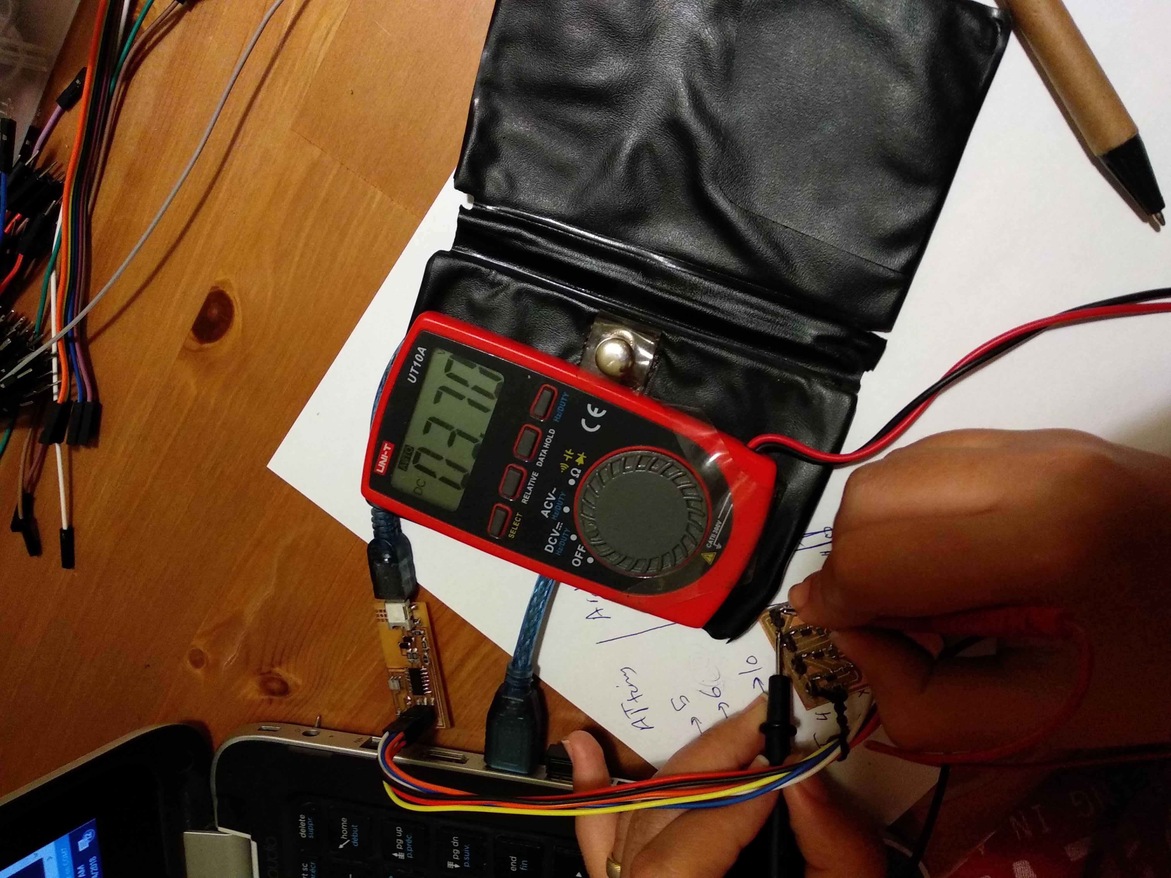
I set all the output pins to transistors gates to be high.
I checked with the avometer that all output power pin headers are now have the power source voltage.
The voltage has been delivered successfully but there were a lot of voltage drom. The output power was 3.7V rather than 5V.
Step3:The LEDs circuits
- I draw the circuit schematic and board using Eagle software.Detailed instructions on how to use Eagle to draw schematic, board and generate requied files for milling visit Electronics production and Electronics design documentation. The design is 5 LED per unit and I need 4 units to be integrated with Final project. I also used through hole leds as I need it to be very bright.
- pin header2 library
- 2 pin header: PINHD-1X02_2.54-SMD
- 3 mm LED:LED3MM
- switched to board mode and made the layout of the PCB
- milling, soldering and testing
- Test the functionaltiy of the circuit
The libraries required for this design:
*all libraries are attached at the end of the page.
The components I used with their names in Eagle:
The schematic of the LED unit.
5 LEDs to be connected in parallel with jumpers to receive the power from the transistors bridge circuit.
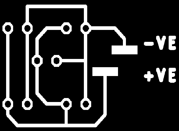

The final board with total dimensions of 3 x2 Cm.
The traces file for milling.
The holes file for drilling.

The outline file for cutting.
I generated 3 files as I had to drilling bit which is different than the cutting bit so I seperated holes and outline cutting in different files.
I used the fab modules with my files exactly the same as I did with the transistors bridge circuit.
For more detailed instructions on how to use fab modules for PCB milling check Electronics production week documentation.
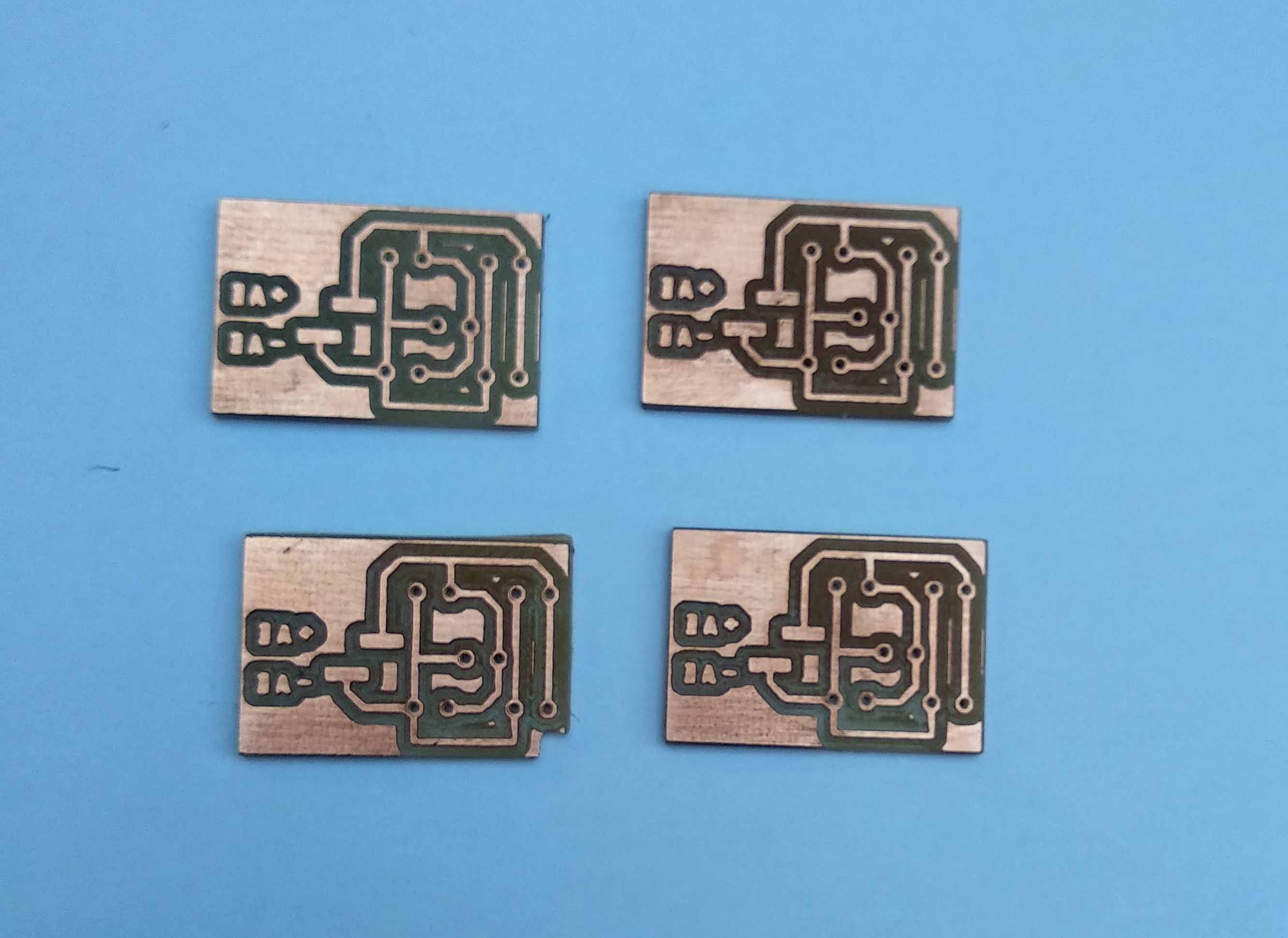
Milling the PCBs.
The milling result.
Before starting the soldering I always check the PCB with Avometer and the buzzer tool for short circuits or unconnected wires.
For this circuit I found No errors.
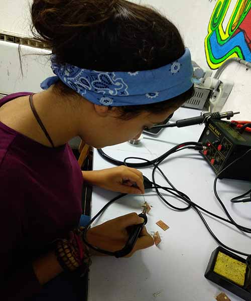
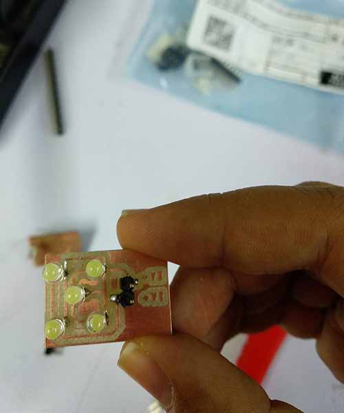
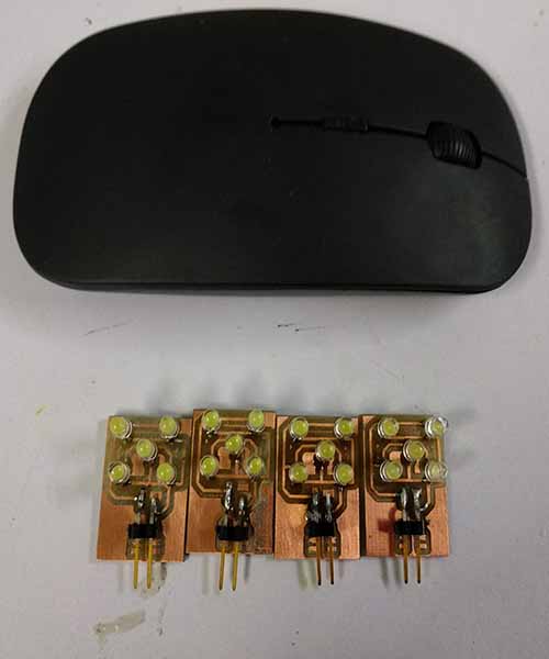
After finishing all the errors prepare the tools and start soldering.
Final LEDs PCB result.
My little tiny LEDs units.
For detaile instructions about how to upload a code on Attiny44 microcontroller check Electronics design week documentation and Embedded programming week documentation.
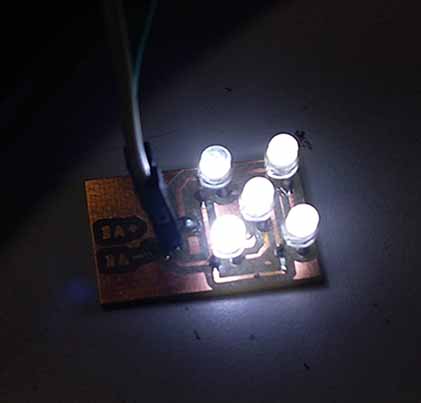
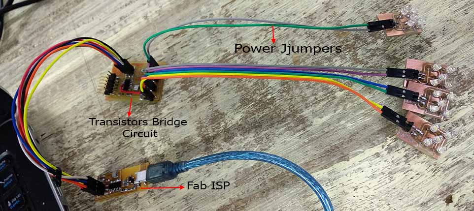
Test the leds by connecting each unit directly to 3V power supply and see if it will light or not.
Connect the LEDS units to the outputs of the transistor bridge circuit to provide them with power and connect the transistors bridge circuit to FAB ISP to program it.
I wrote a code to give signals to the transistors gates and give power to the led units in parallel.
Nice to see it working with Egyptian Popular music (Mahraganat :D).
That's the end of this week.
Files:
*Before using the eagle files for milling please revise the documentation. It shows the errors and how to fix it after manfacturing or you will need to edit on the design itself before manfacturing.
- N-Channel Mosfet Transisotr (NDS355AN) datasheet.
- Attiny 44 datasheet.
- Fab library.
- Pinheader2 library.
- Transistors bridge traces milling file.
- Transistors bridge cutting outline file.
- Transistors bridge Eagle files.
- Arduino testing code for transistors bridge circuit.
- LEDs unit Eagle File.
- LED unit traces milling file.
- LED unit outline cutting file.
- LED unit holes drilling file.
- Arduino code for testing the LEDs units with the transistors bridge circuit.
Resources I used in this week:
- Blink a LED using MOSFET transistor.
- SMD pinheader eagle library.
- Text elements on Eagle.
- What is width error in Eagle.

