Week 8 - Embedded Programming
This week's tasks are:
- Read Attiny microcontroller datasheet.
- Program hello echo board to do something.
- Use different programming languages and programmig enviroments.
Step1: Know more about microcontrollers
I have a previous knowledge with Microcontrollers as I used PIC microcontroller in many projects but I never used AVR microcontroller, so I wanted to recap first some important concepts. (This is just a quick recap of all the links listed down).
- Microprocessor Vs Microcontroller
- Microcontroller families
- AVR microcontroller
- How to program a MCU
| Microprocessor | Microcontroller |
|---|---|
MPU |
MCU |
An integrated circuit used for general purpose computing tasks. |
An integrated circuit used for specific applications only |
Usually used in computers |
Usually used in embedded systems and Engineering projects |
Must be connected to external peripherals to work. ( like memory ) |
It doesn’t need any external peripherals to work. ( it has memory inside) |
It has ALU ( Arithmetic Logic Unit) , I/O ports and Registers |
It has CPU (Central processing unit), RAM / ROM, programmable I/O ports, serial port, timer, And all required components |
In simplest term,
MPU = CPU
MCU = MPU + Peripherals + Memory
Peripherals = Ports + Clock + Timers + UART/USART + ADC + DAC + LCD Drivers + Other Stuffs
Memory = Flash + SRAM + EPROM + EEPROM
There are many Microcontrollers families like 8051, PIC, AVR, ARM to name just a few. These families are different from each other in the processor architecture, Number of registers which means the amount of numbers that can be stored, Speed of execution, number of instructions, peripherals and off course the manufacturer. Each family contains number of microcontrollers which differ from each other in number of ports, number of clocks, amount of memory… So in any project we have to choose the family and then which controller in this family to use.
The family that we will work with is the AVR family manufactured by Atmel. Its architecture is based on RISC, 8 and 32 bits registers. It has high computing performance with better power efficiency according to Atmel website.
You choose an IDE (Integrated Development Environment) which you can install on your computer and write the code on it using a programming language. The IDE work as a compiler, it will extract the machine language from your code. After that the code will be uploaded to the MCU using a circuit connected to both your computer and your MCU.
Step2: Read the Data sheet of Attiny
I started scrolling down in the datasheet through the things that I thought I need to know which are the function of each pin and what I can do with this microcontroller
- The pins
- In any data sheet there is always a part which tells the function of each pin
- Port B can read and send digital Data only but port A has the option of read and send both analog and digital data.
- Every pin must be configured before using to be input or output.
- Peripherals
- 2 PWM channels ( Pulse Width Modulation )
- 8 channels 10 bit ADC ( Analog to Digital Converter)
- 32 general purpose working registers
- 8 bit timer/counter
- connect the hello echo to FAB ISP
- Upload blinking led code
- Program the switch to do something with the LED

| Pin NUmber | Name | Main Function |
|---|---|---|
1 |
VCC |
Supply Voltage |
14 |
GND |
The Ground |
2,3,4,5 |
Port B = PB0-PB3 |
I/O port consists of 4 pins = 4 bit port |
6,7,8,9,10,11,12,13 |
PORTA= PA0-PA7 |
I/O port consists of 8 pins = 8 bit port |
These are the main functions but each pin can be used in other functions
The ATtiny has:
There are all the details that anyone needs to know about ATtiny in the data sheet so I thought it’s better to check it again when I need any information and I will update it here .
Step3: Programming the board
On the week of Electronics Design , I tried programming hello echo using Arduino As an ISP and Arduino IDE also using Fab ISP and AVRdud (For more info go to week 6 documentation on step 6). So I decided to focus this week on the programming itself using Arduino IDE and Fab ISP.
We will upload the code to the hello echo through the FAB ISP programmer we made atweek 4.
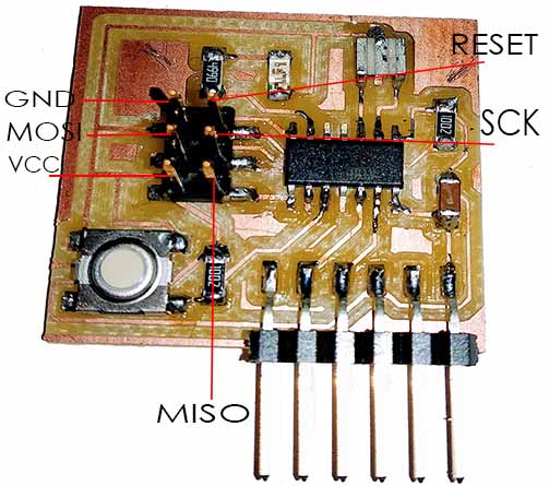
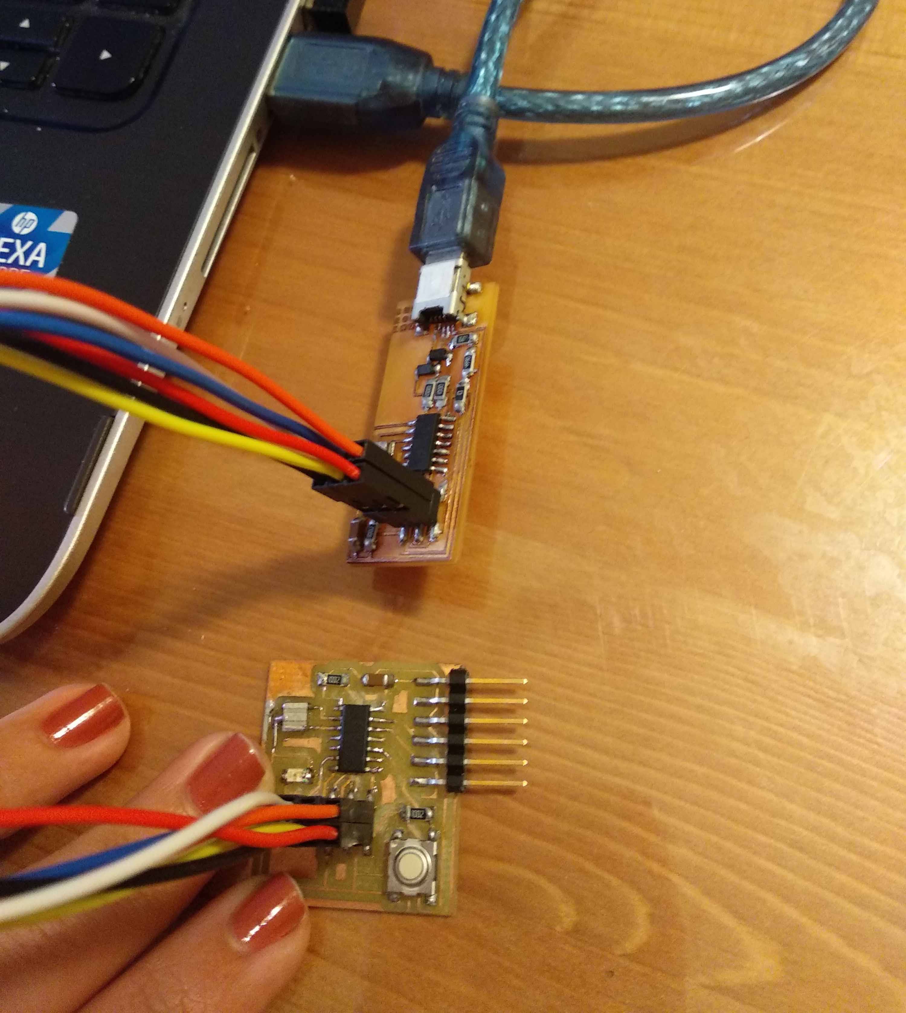
I connected every pin on Fab ISP board to it's coressponding on Hello Echo board and then connected the Fab ISP to my computer
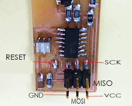
FAB ISP header pinout
Hello Echo header pinout
Hello echo board connected to Fab ISP connected to computer
I prefer going step by step in coding for easier debugging so I decided to program the led only with the blinking led example in the arduino IDE then upgrade by using the switch.
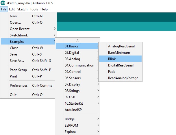
From Arduino IDE select File>Examples>Basic>Blink
In the sketch the led is connected to pin 13 of the Arduino board. This should be changed to the pin where I'm connecting the led.

There is no 13 pins on attiny so to be able to program it from the arduino IDE each pin of the attiny has its corresponding one on the arduino.
I'm connecting the led to pin 6 of the Attiny, According to the figure it's corresonding to pin 3 or 7 of the Arduino. 3 didn't work for me but when I changed it to 7 it worked.
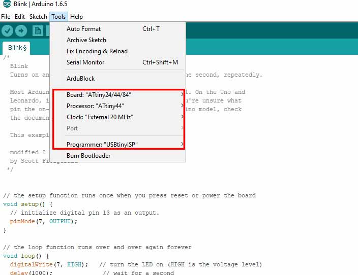
I Changed pin 13 in the code to pin 7
Make sure settings are correct
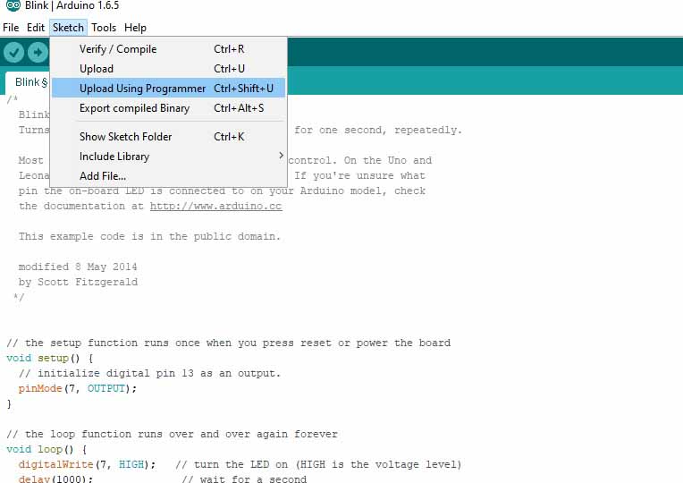
From sketch select upload using programmer.
Done uploading.
The LED is blinking Successfully
I programmed the led to blink only when the switch is pressed
void setup() {
  // put your setup code here, to run once:
pinMode(7,OUTPUT);     //Arduino pin 7 =Attiny44 pin 6 which is connected to LED
pinMode(3,INPUT);      // Arduino Pin 3 =Attiny44 pin 10 which is connected to a button
}

void loop() {
  // put your main code here, to run repeatedly:
int button=0;         // create a variable for the button signal and give it an intial value of 0

button=digitalRead(3);
if (button==LOW){
while(1){            //Start a forever blinking loop
  digitalWrite(7,HIGH);
  delay(1000);
  digitalWrite(7,LOW);
  delay(1000);
 button=digitalRead(3);
}
}
 else{
  digitalWrite(7,LOW);
}
}
End of This week

