Networking and communication

This week's tasks are:
- design and build a wired &/or wireless network connecting at least two processors.
- Use Adressing (board Identity).
For this assignment I decided to use two of my boards that I have already made: Hello Echo board and Transistors bridge board and use the serial communication protocol.
Serial communication Vs Parallel communication
Parallel interfaces transfer multiple bits at the same time but Serial interfaces stream their data, one single bit at a time.
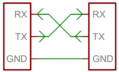
Serial interfacing is like what we have done in most of the boards we made in Fab Academy like (Hello Echo) to send signal through one pin which is Tx and receive the signal through another pin which is Rx. So it make it simple instead of using one board and FTDI I will be using two boards and connect Tx of the 1st board to Rx of the second board and vice versa.
Step1: test the serial communication of my boards
I tested my boards individually to check if serial communication is working and there are no errors because of soldering or any unworking component. For the hello echo board I already checked it's serial communication functionality at week 6.
For the transistors bridge board that I have made for another purpose in output devices week., I tested it bu also trying to upload the hello echo code.
For more detailed instructions about hello echo code and how to upload it check week6 documentation.
Weird charachters appeared in the serial monitor.
Serial is working functionally after burning bootloader.
When I uploaded the code and opened the serial monitor weired charachters appeared which was not supposed to happen with hello echo code!
When I burned the bootloader and re uploaded the code it worked as expected. I don't really understand why does this happen but it solved the problem anyways.
The two boards now are tested and working fine.
Step2: write a master and slave code
Master code
Slave code
I wrote the above code by configuring the Tx and Rx pins at each board, sending Hello from the master board, Receving the serial data from the slave board that has a LED and if there were data through serial bus the LED should blink.
I uploaded the code using my Fab ISP on both of the boards then I connected then to each other using the serial connection TX,RX,VCC,GND.
For my luck it worked from the first time and led was blinking when receiving from serial.
Step3: try doing the addressing
Adressing is to have one master and multiple slaves and send certain data to certain node (one of the slaves ) to do a certain action.
As I'm doing this assignment with only two boards I simulated the addressing by giving the board a node number and if it's receiving its node number it will take an action, if not it will not take any actions.
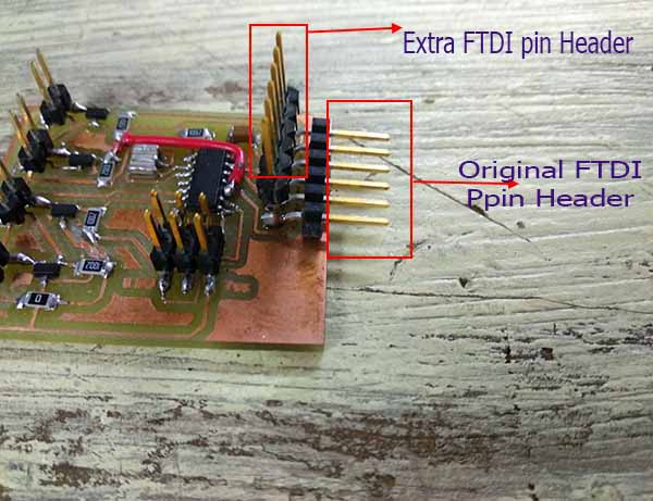
Soldering Extra FTDI pinheader.
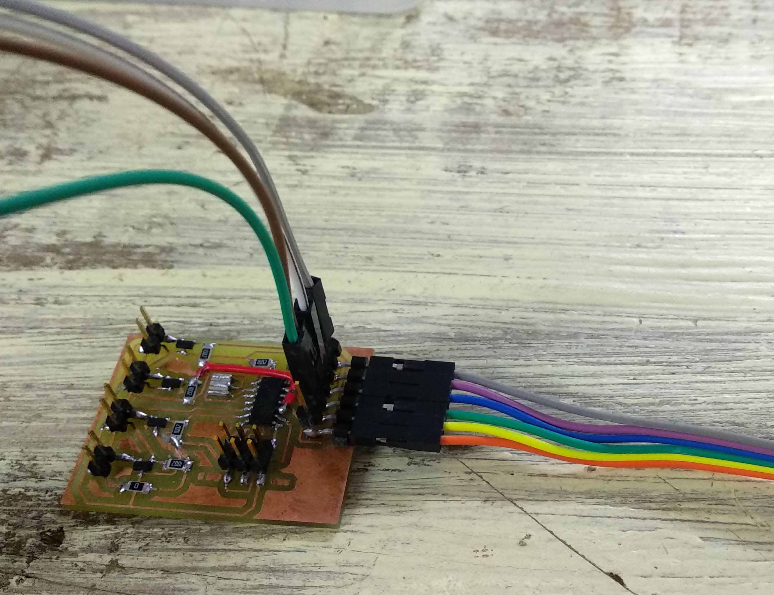
connecting two serial communication wires at the same board.
I realized that if I want to connect two boards with serial lines then connect also one of them through FTDI to my pc, I propablly should have to onsider this in my design and provide the master board with two FTDI pinheaders.
Since I didn't do that I soldered one FTDI pinheaders above the old one in the master board it it woked for me.
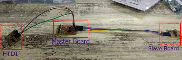
Connecting the master and slave together then connect them to PC through FTDI.
Master code
Slave code
I gave the node a number of 5 and it will check the comming data. If the data have its node number which is 5, the LED will blink and the slave will send back to the master a confirmation message. If the data doesn't have its node number, the lED will not blink and it will send a rejection letter to the master.The master should print the message it receives from the slave through the serial monitor.
Data received through the serial monitor is shifted.
The slave recieved the data and blinked the led also sent the message but I noticed a delay in the whole system also the messages that were sent through the serial monitor was shifted and not sent correctly.
This was because I only had one serial communication bus and I was trying to do sending and receiving at the same time as in the te master coder it sends the node number forever and the slave should respond through the same bus line!
So I decided to send the serial signal once.
Step4: make the communication happens depending on a certain action
Master code
Slave code
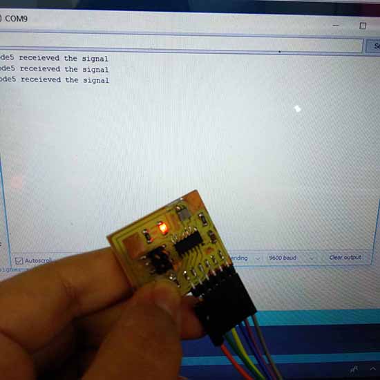
I switched the master and the slave boards. Made the board with the LED and the push button is the master that sends the node number and confirm its sending by blinking a led. And made the other board as the slave that receives the signal and confirms receiving by send message through the serial monitor.
it worked perfect
Files:
Resources I used in this week:
- What is I2C communication
- Communication between two arduino boards tutorial.
- Arduino functions documentation.
- Parallel Vs Serial communication.

