Final Project - Galaxy Box
What is the project idea and what should it do ?
The project is a lightining unit that has 4 photos and these photos will only appear when they are lit up.The whole unit will be synchronized with music beats. It is related to art, technology and music and how they can be mixed together to give a unique enjoyable experience. It also represents the magic of light and how the light and darkness can change the whole scene.
The project has been formulated through the final project proposal which was to make something similar to led cube but in a spheric shape and can be synchronized with music to end up with a whole different technology.
As I love LEDs, I once made a 8x8x8 led cube with My husband to show it in Maker Faire Cairo. After the maker faire we used it to decorate our home.The led Cube plays patterns in a certain time sequence but I always wanted to sync it with the music and this was the start of the idea.
Steps and processes
no |
Task |
Process |
Link |
|---|---|---|---|
1 |
Choose pictures to be 3D printed and print it. |
3D printing |
Experminting the cocept has been made through trials in wild card week. |
2 |
Design an enclousre box to hold the 3D printed photos, The LEDs and all the control circuits. |
2D design |
|
3 |
Fabricate the enclousre. |
Laser cutting |
|
4 |
Design a circuit that can capture the audio signals through an electret mic. |
Electronics design |
Has been completely done at Input devices week. |
5 |
Fabricate and test the audio signal circuit. |
Electronics productiom |
Has been completely done at Input devices week. |
6 |
Design a circuit that can control 4 LEDs' units( Transistors bridge circuit+ LEDs circuits). |
Electronics deign |
Has been completely done at Output devices week. |
7 |
Fabricate and test the transistors bridge circuit |
Electronics production |
Has been completely done at Output devices week. |
8 |
Fabricate and test the LEDs units circuits. |
Electronics production |
Has been completely done at Output devices week. |
9 |
Communicate between the audio signal circuit and the transistors bridge circuit |
Networking and communication |
Test communication has been made at Networking and communication week. |
10 |
Write the final programming code |
Embedded programming |
Reading the audio signals has been successfuly made at Input devices week and controlling thr LEDs has been successfully made at Output devices week. |
11 |
Integerate all of the above together. |
||
12 |
Prepare a video and one slide. |
Bill of materials
no |
Material |
Cost($) |
Source |
|---|---|---|---|
1 |
Wood sheets |
1.5 |
From local supplier |
2 |
3D printing Filament |
25 / 1kg roll |
Any filament supplier |
3 |
6 x 10 Kohm resistor |
0.18 |
Digi-Key (also should be in your inventory) |
4 |
4 x 100 ohm resistor |
0.18 |
Digi-Key (also should be in your inventory) |
5 |
1 x 2.2 K ohm resistance |
0.25 |
Al-nekhely for electronics> |
6 |
0 ohm resistance |
0.1 |
Digi-Key (also should be in your inventory) |
7 |
1 x 10k ohm variable resistance |
0.5 |
Al-nekhely for electronics |
8 |
3 x 10 uF capacitors |
1 |
Digi-Key (also should be in your inventory) |
9 |
6 x 1 uF capacitors |
2.5 |
Digi-Key (also should be in your inventory) |
10 |
5 x 1 pF capacitors |
3.5 |
Digi-Key (also should be in your inventory) |
11 |
2 x ATTINY44 |
2.5 |
Digi-Key (also should be in your inventory) |
12 |
2 x ISP pinheaders |
3.5 |
Digi-Key (also should be in your inventory) |
13 |
(2x1) pinheaders |
5 |
Digi-Key (also should be in your inventory) |
14 |
2 x 20MHZ oscillator |
2 |
Digi-Key (also should be in your inventory) |
15 |
2 x 0.1 uF capacitors |
2.5 |
Digi-Key (also should be in your inventory) |
16 |
1 x LM4861 Amplifier |
3 |
Digi-Key (also should be in your inventory) |
17 |
5V voltage regulator |
0.6 |
Digi-Key (also should be in your inventory) |
18 |
Electret mic |
0.5 |
Ram electronics |
19 |
4x N-channel NDS355AN mosfet transistor |
6 |
Digi-Key (also should be in your inventory) |
20 |
20 x 3mm white LED |
0.25 |
Ram electronics |
21 |
1x 9V battery |
1.5 |
Ram electronics |
Total cost |
63 $ |
Steps1: choose photos and print it.
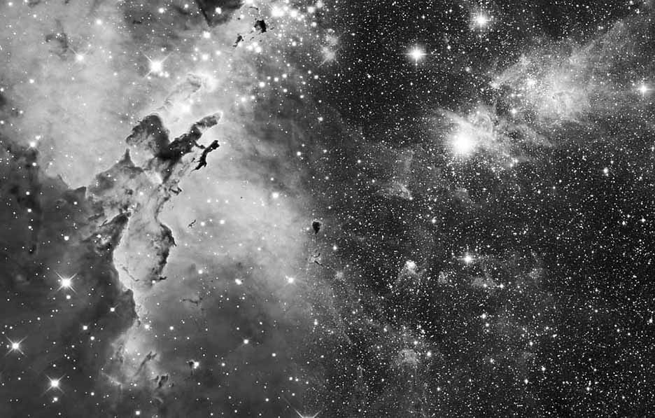
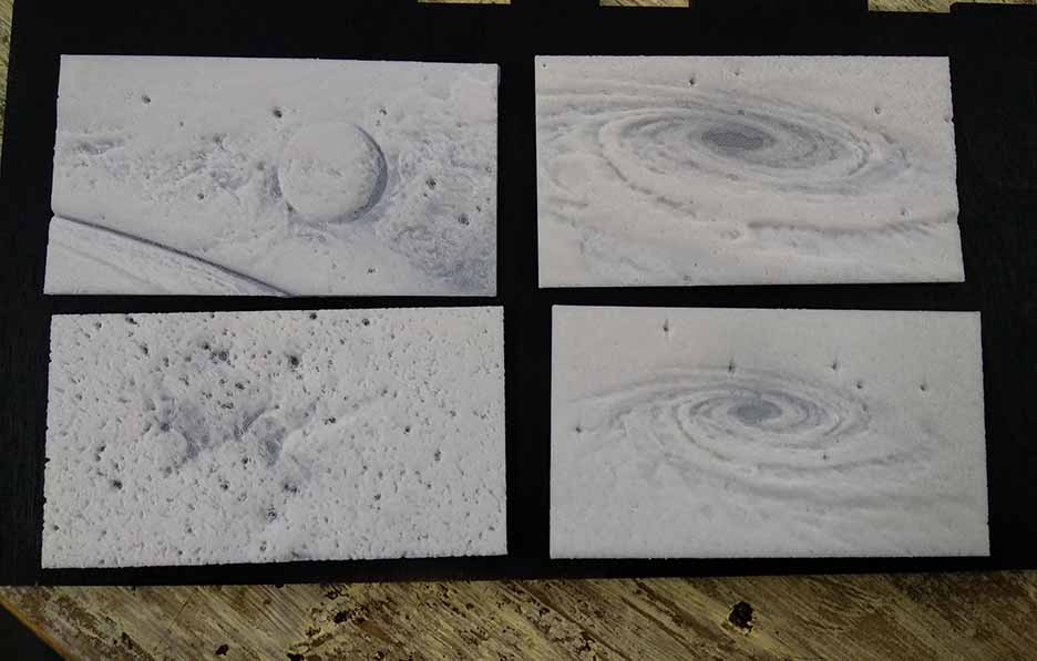
The technique I'm going to use is lithophane where you 3D print images and it only appears when it is lit up. It depends on the difference in the intensity of light passing through dark and bright parts of image.The 3D printer puts more material in dark parts so it doesn't pass light and less material in the bright parts so it passes light.I have explained more about this technique and the trials I made at Wildcard week.
- Choose the photos:I decided to make it (a galaxy box) and choose all the photos to be from different galaxies around the universe.
- Make edits: After trying the 1st one, I decided to converted these images to black and white to check how it might look like after 3D printing. I then had t edit on the contrast and brightness of some photos to make bigger difference between dark and bright points.
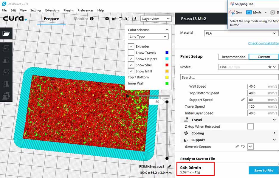
- Prepare files for 3D printing: I used cura software to slice the photos and make
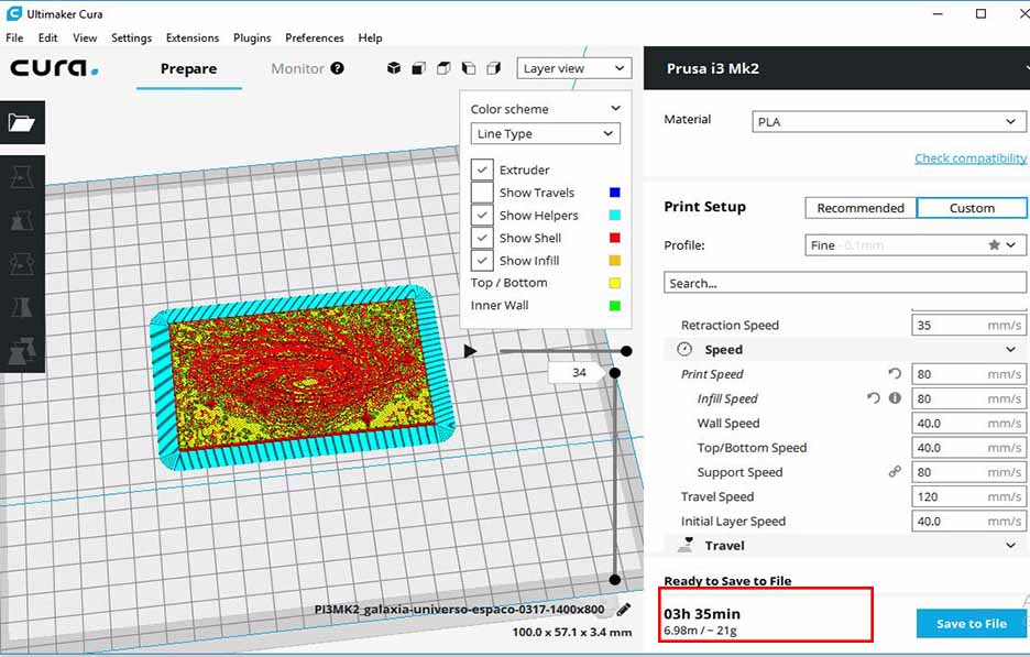
- printing:I printed the images using Prusa MK2 i3 3D printer. It took about 65g and 17 hours to print all the photos.


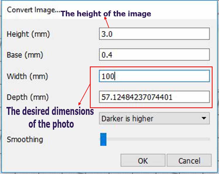
These are the settings I made for the 1st file. For more details about theses settings please check wild card week documentation.
Preview of the 1st photo.
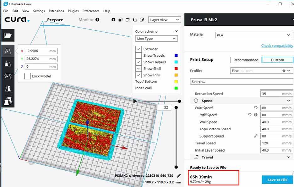
Preview of the 2nd and 3rd photo. I kept the dimensions the same and changed the base to be 0.2
Preview of the 3rd photo.
Steps2:Design and fabricate the photos enclousre
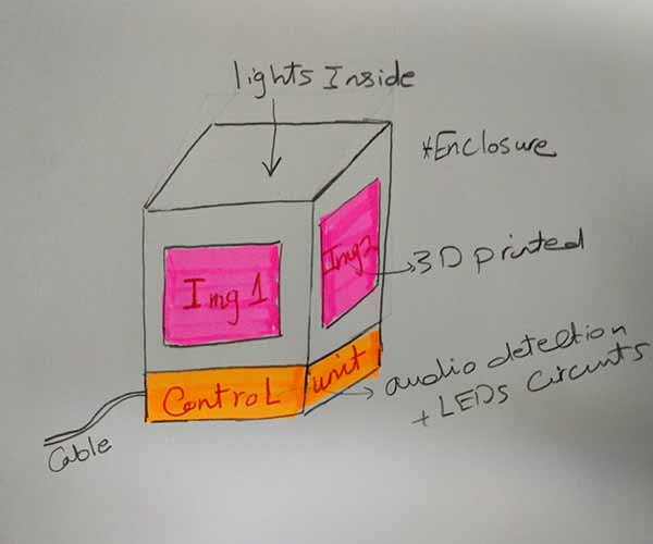
- Sketch the design: I first sketched the enclosure. It will be a box that has 4 openings for the 4 3D printed potos to be fixed in.
- Make the design:I used in this design makercase and inkscape. This box was designed for 3 mm wood sheets and has dimesnions of 120 x 120 x 110 mm.
- Fabricate using laser cutting machine:
This box will be fixed on the top of another box to hold the circuits, wires, mic, batteries and all stuff.
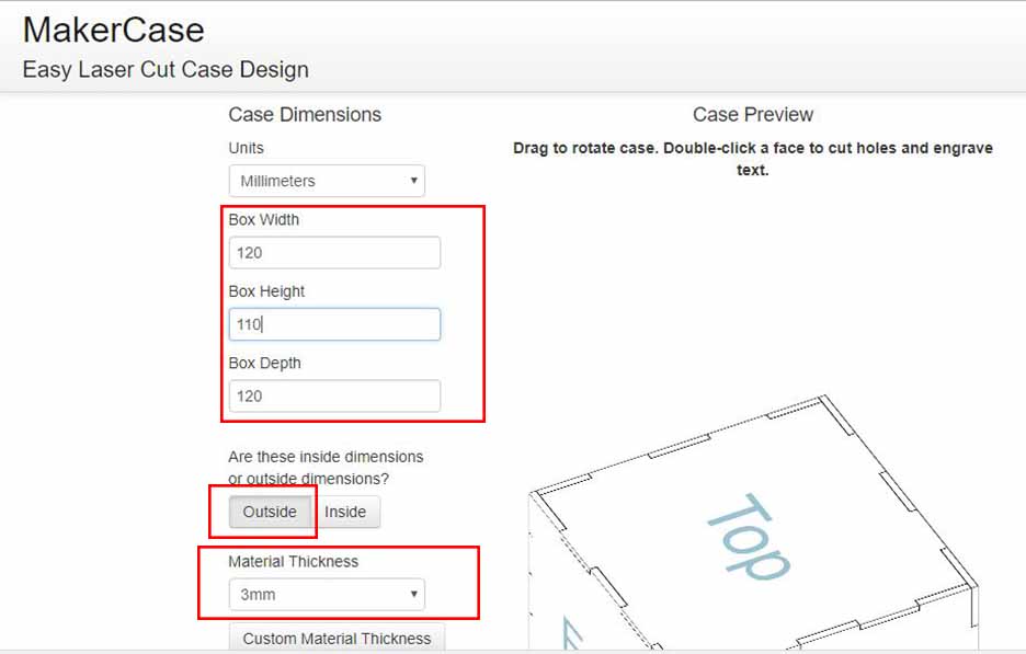
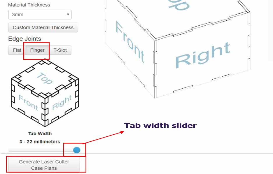
Open makercase website > select the width, depth and height of the box > choose dimensions to be outside not inside > choose the material thickness to be 3mm.
Choose the edge joints (finger) and slide the tab width to its maximum which is 22mm. Ater that click on generate laser cutter plans.
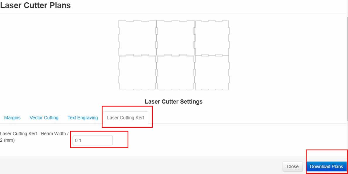
A setting window will showup, I left all settings the same and changed only the kerf to be 0.1 mm (this is the kerf of our machine). Then I clicked on woenload plans.
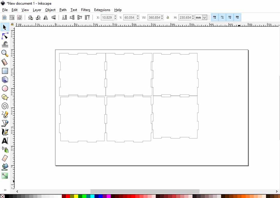
Open inkscape and import the design downloaded from makercase (it will be on SVG) format.
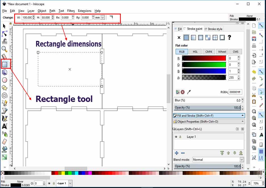
draw rectangle with a dimension of 99 x 50 mm which is slightely smaller than the photos printed
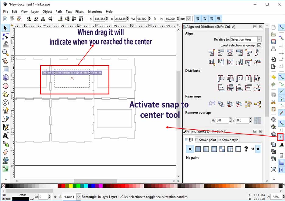
Activate the snap to center tool and drag the rectangles to the center of each part.
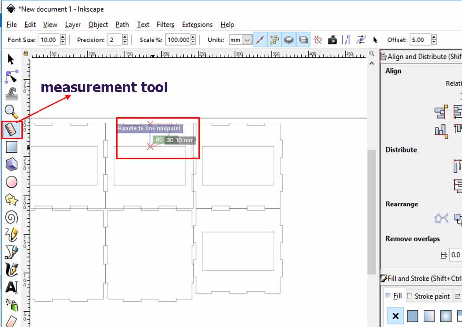
use the ruler tool to make sure that they are at equal distances and repeat this for all of the box parts except the top.
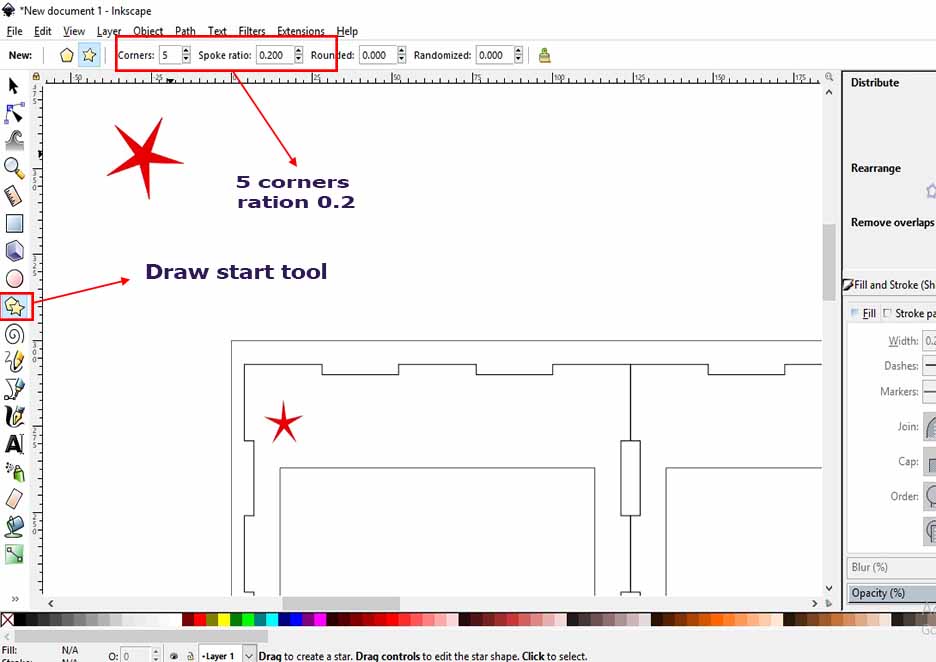
Draw start with 5 corners and 0.2 ration. Make sure that there is fill and stroke at the same color but the starts are in different color than the box parts.
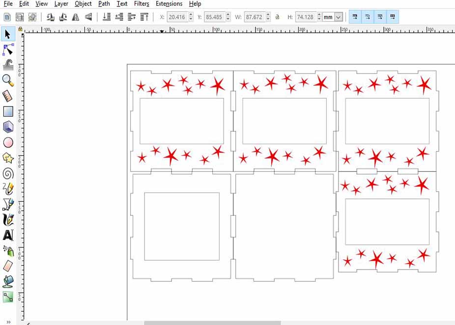
repeat stars at different sizes then export the whole design as dxf and as SVG.
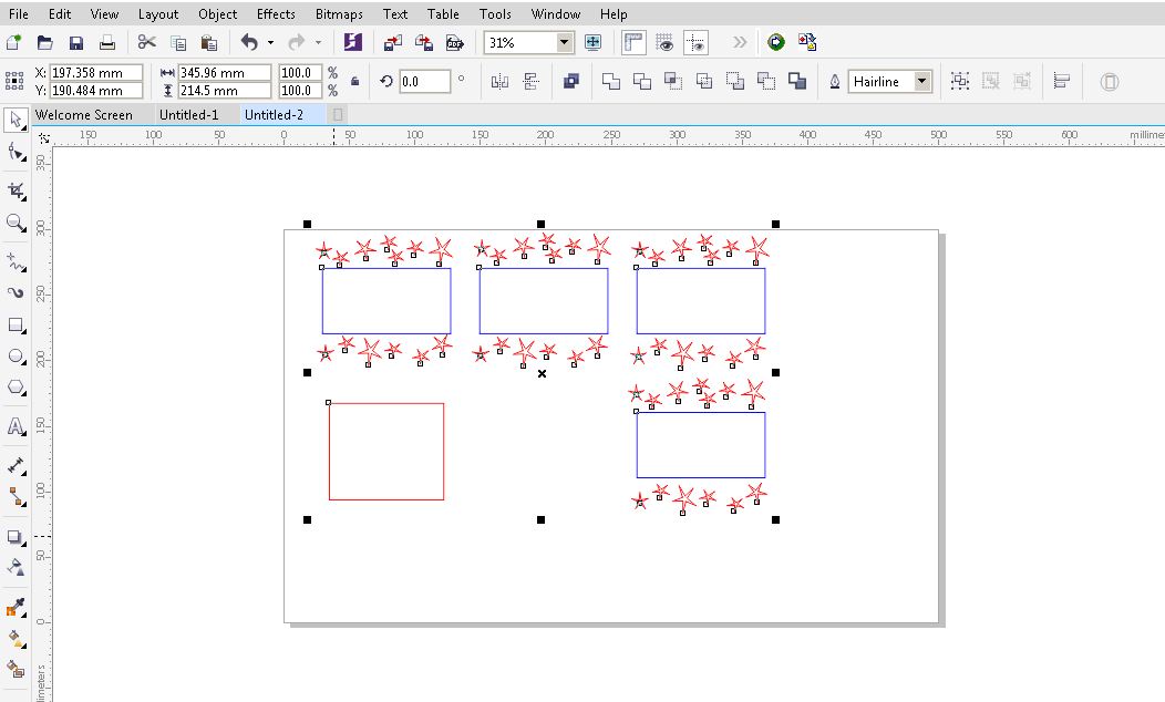
Open coral draw as it is connected with our laser machine. Import the DXF file but it was not correct as the whole box was missed I don't know why.
I imported the DXF file and it was fine but needs some edits.
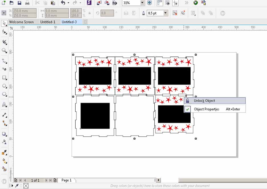
Right click and unlock the objects.
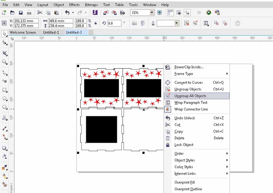
Then right click again to unlock all objects.
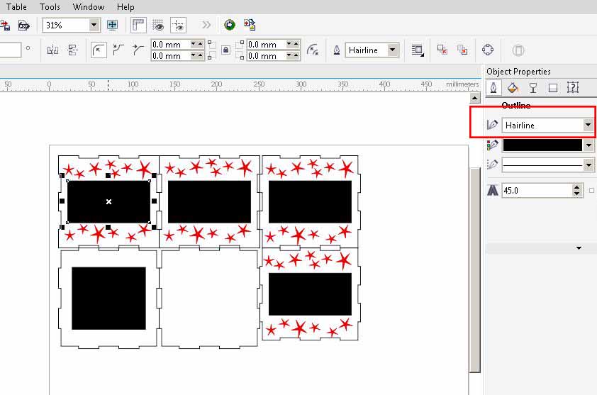
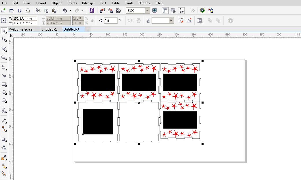
Make sure that all lines are hairline.
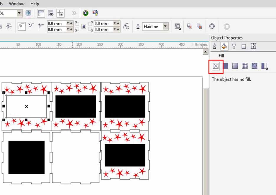
Mark no fill for all inner rectangles.
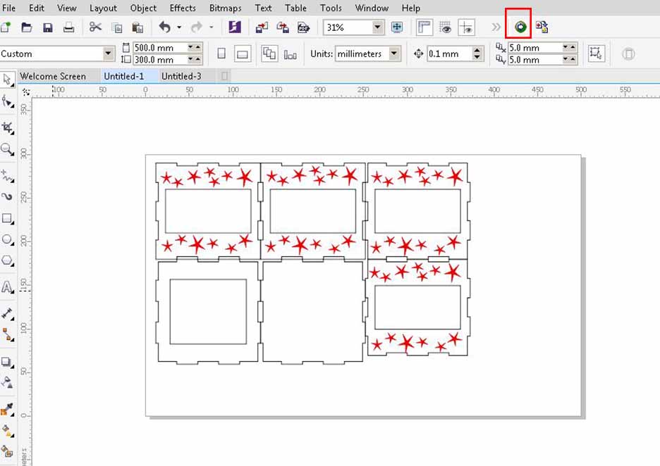
Press on laser run.
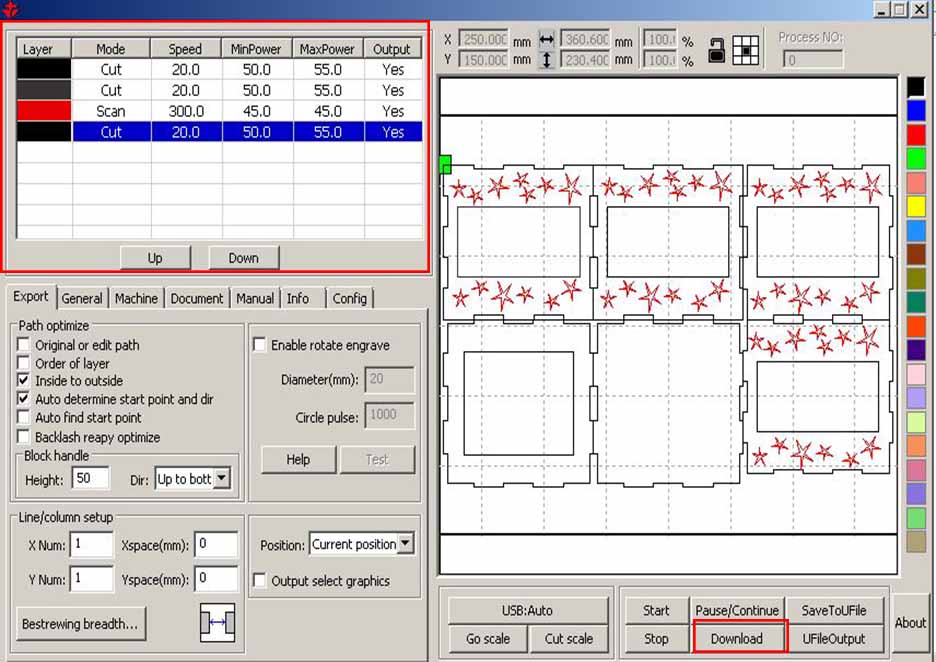
Put all the settings (cutting power 50 cutting speed 20 mm/sec, scanning power 40 scanning speed 300 mm/sec). After that download the file on the machine.
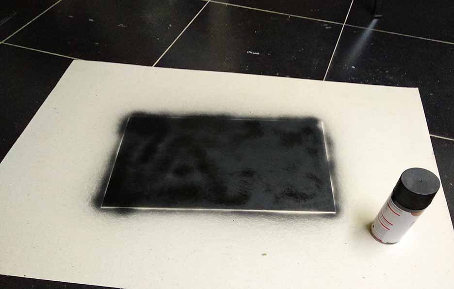
I paint sprayed the wood sheet with black color before putting it on the machine and let it dry completely.
Laser cutting.
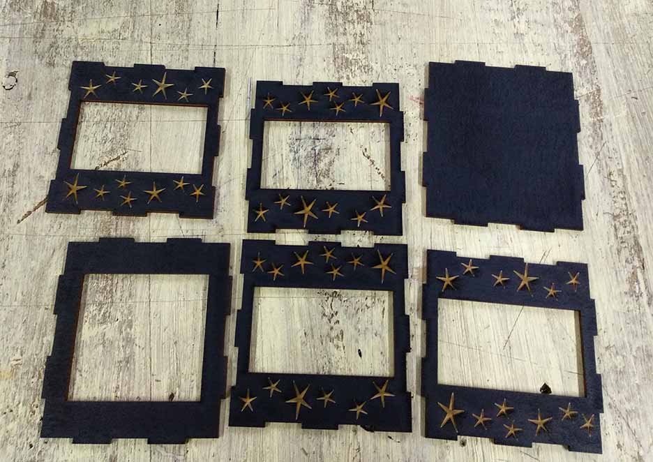
The laser cutting result
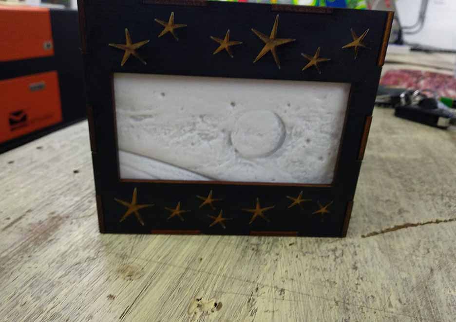
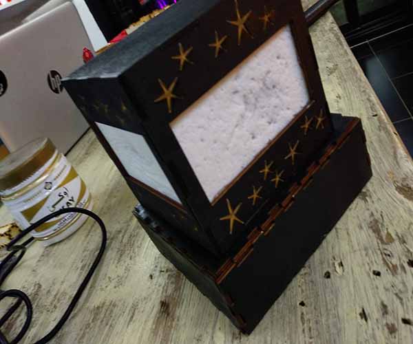
I fixed the 3D printed photos in the openings of the box then I assembled the box.
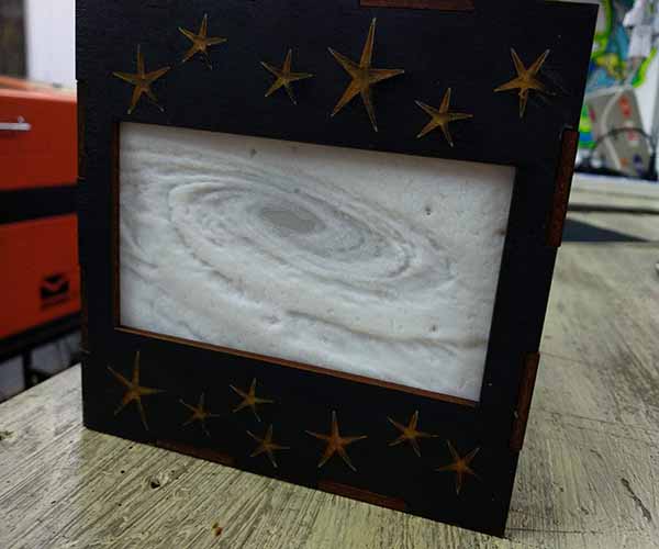
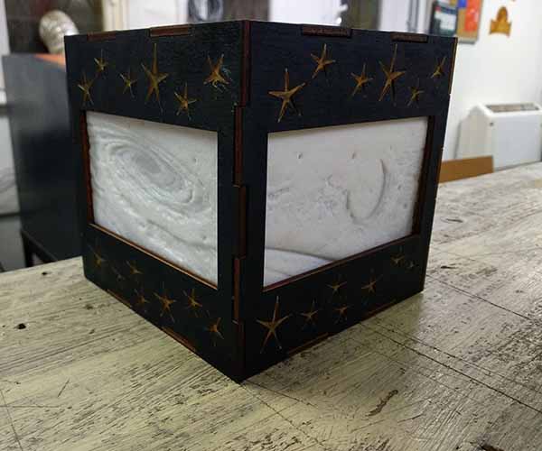
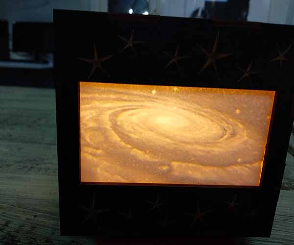
This is the result of my galaxy box and trying to lit it up with my mobile flash light.
Steps3:Input and output circuits
- Drafting of the control system:I started to think how I'm going to capture the audio signals and control LEDs using these signals.
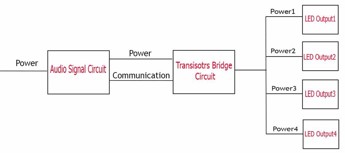
- Audio detection circuit: This circuit has an electret mic that captures the audio signals and an amplifier that takes these signals and amplify it to higher values to make it readable. It transmits the amplifier output and power to the transistors bridge circuit through serial communication.
- Transistors bridge circuit: This circuit recieves its orders from the audio detction circuit through serial communication and accroding to these orders 4 transistors control the delivery of power to 4 different LEDs units. The main purpose of using this circuit is not to let the curret needed by 5 LEDs to pass through the pins of Attiny as this much of current will destroy it.
- LEDs circuit: Each LED unit has 5 leds which are controlled to be on or off ( all the 5 LEDs of each unit work together) through receiving or not receiving the power from the transistors bridge circuit.
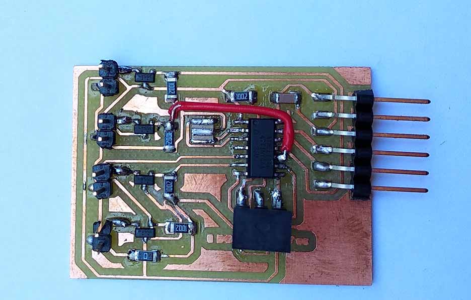
- Fabricating the audio detection circuit: The design has been made by Eagle and the board has been fabricated using Modella MDX-20 and Fab modules.
- Fabricating the transistors bridge circuit: The design has been made by Eagle and the board has been fabricated using Modella MDX-20 and Fab modules.
- Fabricating the LEDs units circuits: The design has been made by Eagle and the board has been fabricated using Modella MDX-20 and Fab modules.
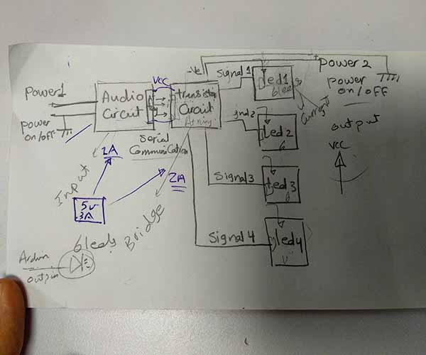
Hand sketch of the control system
Control system diagram (Input, output, power, communication)
The control system consists of three main circuits as shown in the diagrame above:
This circuit has been designed, Fabricated, analyzed and tested at input devices week.
This circuit has been designed, Fabricated, analyzed and tested at output devices week.
This circuit has been designed, Fabricated, analyzed and tested at output devices week.
The power intlet is at the audio detection circuit and it is transmitted from it to the rest of the circuits one after another.
To know how the circuits were designed, how components were chosen, how each circuit exactly works and how the circuits were tested check the documentation of the weeks mentioned above.
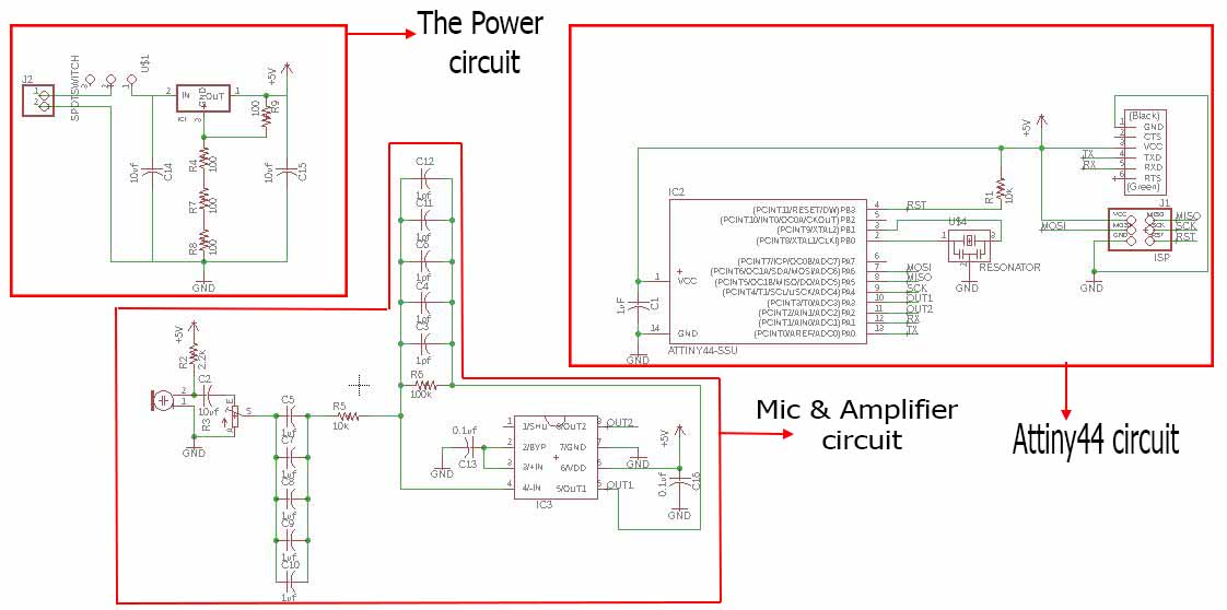
Audio detection board schematic
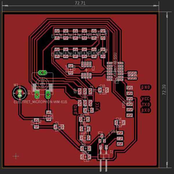
Audio detection circuit board
Audio detection board final result
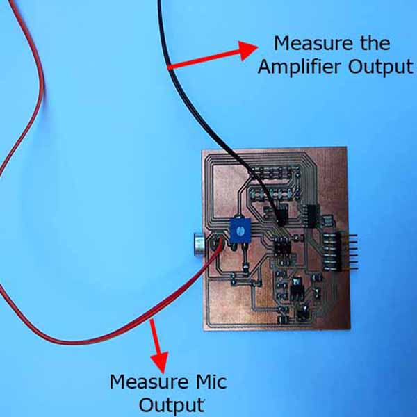
Testing the board output using oscilliscope
Transistors bridge board schematic
Transistors bridge circuit board
Transistors bridge board final result
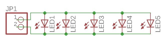
LED unit board schematic
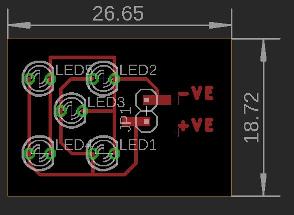
LED unit board
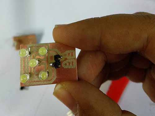
LED unit board final result
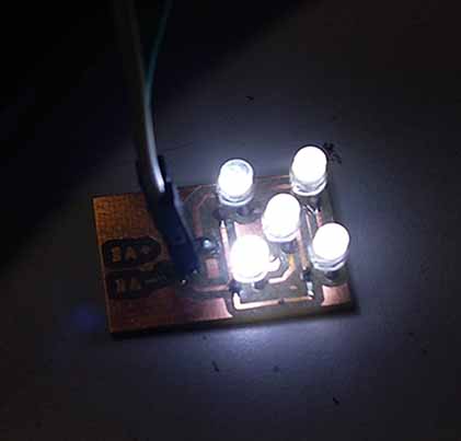
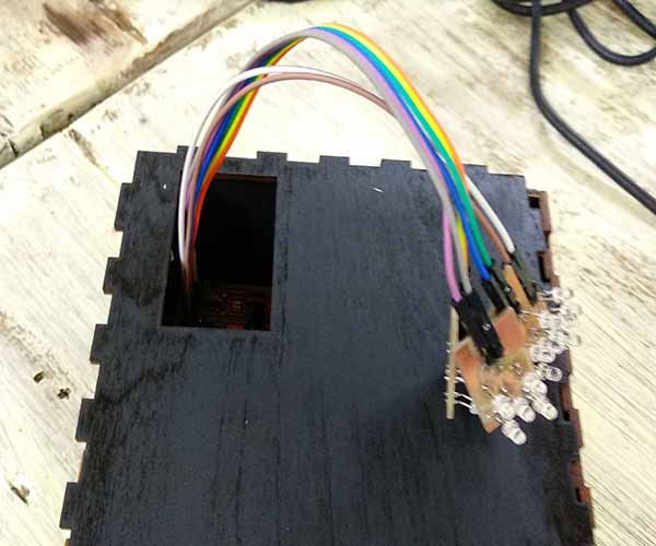
LED unit testing
The four LEDs units testing
Steps4:Design and fabricate the control unit enclosure
After finishing all my circuits and with knowing the dimensions of my main components I tried to figure out how to design the box that will hold all these components.
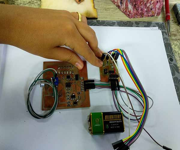
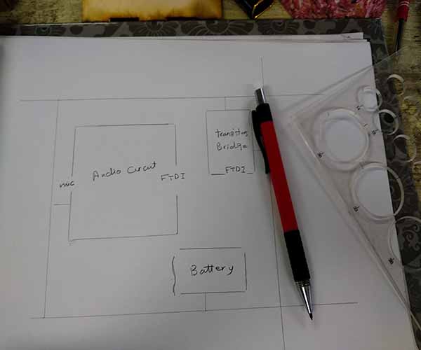
I brought a white paper and arranged my circuits and main components on it.
With a pencil I draw lines around each component then I draw a rectangle that holds all the components at equal distances.
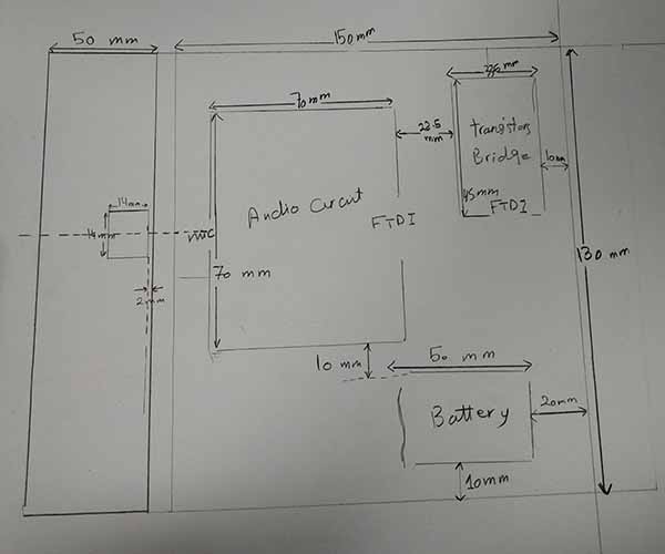
I started to measure and write down all the dimensions I will need in designing.
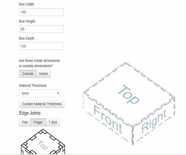
I went to makercase again and downloaded a pressfit box of dimensions of( 150 x 130 x 50 mm).
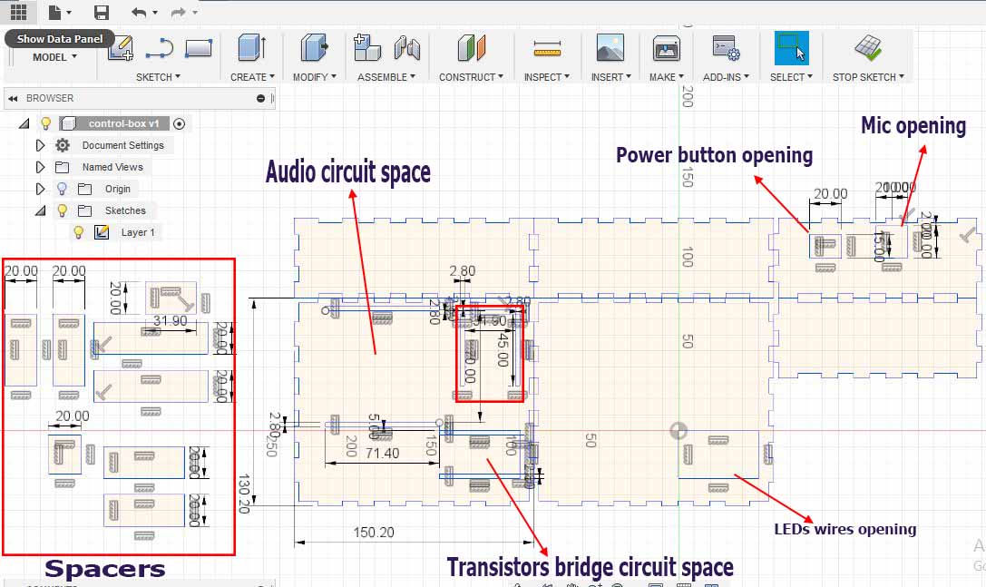
Control Box design
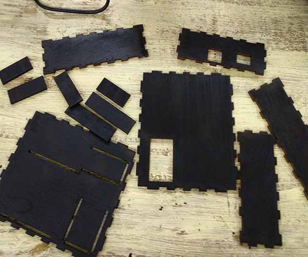
Laser cut the box
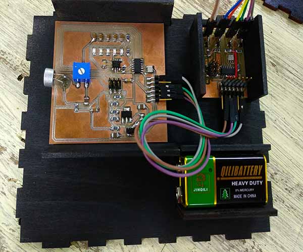
Fix the circuits in their places with the spacers.
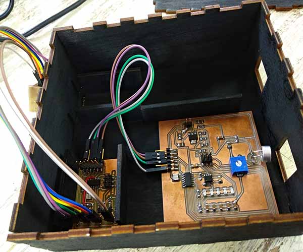
Assemble the box
put the cover and pass the leds through the opening on the top
Steps5:The coding
The code is working on a way that the audio detection circuit reads the audio signals then divide it to 4 ranges and send through serial to transistors bridge circuit the range number. According to the recieved number the transistors bridge circuit will deliver power to the LEDs units in certain sequence to act as a visualiser.
- The audio detection circuit code: The code is very similar to the code I used in Input devices week. You can check the documentation for more details about the code.
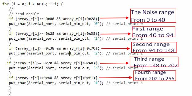
- If the reading is between 0 and 40 a zero number will be sent to the transistors bridge circuit to set all LEDs units to LOW.
- If the reading is between 40 and 94 a "1" number will be sent to the transistors bridge to set LED unit number one to HIGH
- If the reading is between 94 and 148 a "2" number will be sent to the transistors bridge to set LED unit number one and two to HIGH
- If the reading is between 148 and 202 a "3" number will be sent to the transistors bridge to set LED unit number one, two and three to HIGH
- If the reading is between 148 and 202 a "4" number will be sent to the transistors bridge to set LED unit number one, two, three and four to HIGH
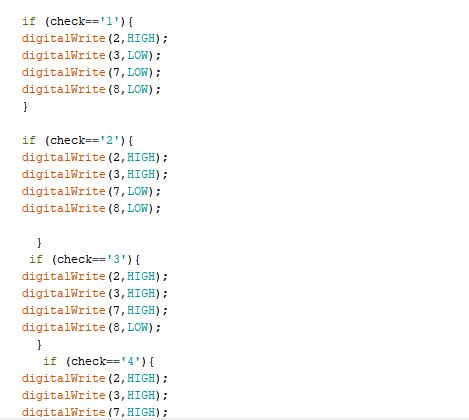
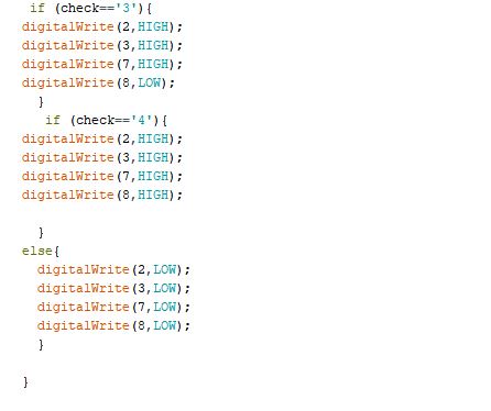
- The Leds Code: The code is written to receive the serial data from the audio detection circuit and it will behave according to the mentioned sequence above
The changes I made are:
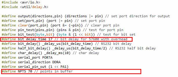
I speeded up the baud rate to 57600 as I notices some delay in the LEDs interaction by making the bit_delay only 17. I also decreased the buffer points to 70 instead of 100 as I had low memory issue when it was 100.
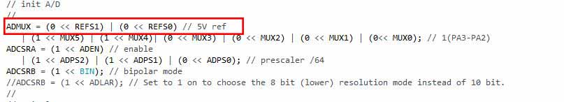
I changed the voltage refrence to 5V by making the refrence registers to 00 to increase the level of the voltage read.
Send numbers through serial according to the readings.
By testing I found that the level that my circuit can read is between 40 and 256. Below the 40 is just the noise or any normal sound and it can't read anything over 256.
I put 5 if conditions:
Ranges values should be written to their HEX equivilants and the numbers should be sent as character and between single quotations.
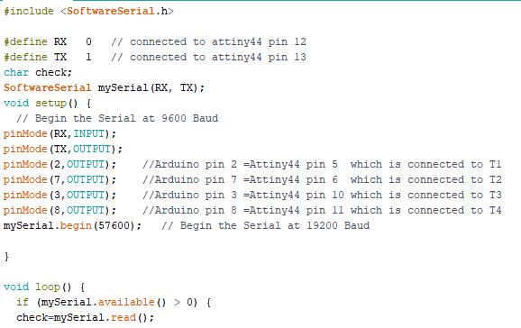
Define serial communications and check if its available
Acknowledgement
I'd like to thank:
- Our Local Instructors: May Eldardiry and Mohamed Abu Elhaggag.
- Our Global Instructor: Ohad MeyuhasYour commitment and Challenges pushed us to get the best out of our selves.
- My colleagues
- Fab Academy alumni: Aser Nabil and Abdullatif Albarodui: Thank you guys for your friendship and for giving me all the needed support, knowledge and help.
- Omar Elsafty- Fab Lab Egypt General Manager: Thank you for giving me the opportunity and for supporting me during ups and downs.
Special Thanks to My beloved husband
You are a true friend, a great instructor and an amazing lover. Every time I got surprised by how much knowledge you have and how much you care about my success like if it is yours. I could never ever do it without your support and your help. You saved me in the dark times and pushed me as hard as you can. Thank you for every electronics tip and trick, for every moment you spent in helping me and for every motivative word. I love you to the moon and back.
Files:
- Galaxy 1 for 3D printing with Prusa 3D printer.
- Galaxy 2&3 for 3D printing with prusa 3D printer.
- Galaxy 4 for 3D printing with prusa 3D printer.
- Galaxy box design for laser cutting the enclosure of the photos.
- Control unit box for laser cutting.
- The audio detection circuit code
- The LEDs units code to be uploaded on transistors bridge circuit.

