Week 13
Networking and Communications
assignment
Group Assignment
1- send a message between two projects
Individual Assignment
1- design and build a wired and/or wireless network connecting at least two processors


Networking and Communications Assessment
.MAKE FILE Download
This means that devices will be inter-connected and can exchange data through interlinking circuits. From my understanding it involves building physical boards and programming them in a network with shared communication protocols.
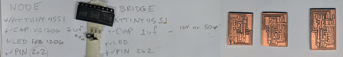
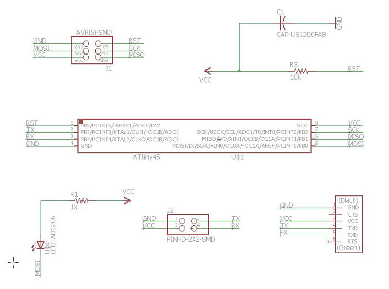
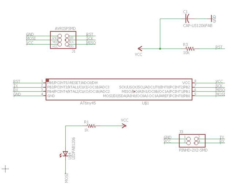
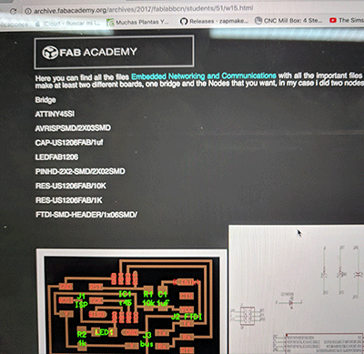
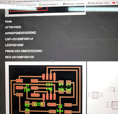
I downloaded the schematic design for the three boards I would be building, a bridge/master and two nodes/slaves. I opened them in Eagle and laid out a board design that worked.
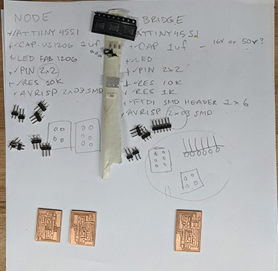
I selected the components from our inventory and laid them out.
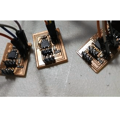
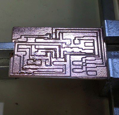
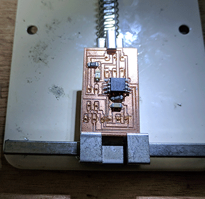
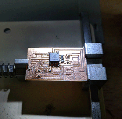
I used ArtCAM to prepare the gcode and used GRBL controller to mill the boards and soldered the components in place.
Once completed I connected to our AVRISP mkll to make sure the boards were correct and touched up any solders.
PROGRAM
I connected the bridge to one side of the FTDI and the other to the AVRISP. Next, in Terminal I opened the files I downloaded for the assignment and found the line of code for their node value. Using ID Arduino, I set the node values separately for each board 0 in this case. This means the microcontroller will be assigned a value that allows it to communicate through the TX port and RX port (UART communication protocol).
Then I ran the make file:
make -f hello.bus.45.make program-usbtiny.
Next I did the same for the nodes, but applied an external power source through a 5v power supply since they don't have an FTDI pin. I assigned values to each of the nodes 1 and 2 and ran the make file to set each node one by one.
Using this type of network, the bridge/master sends one character using its TX port and the nodes/slaves receive it using its RX port. With the boards programmed I connected them physically.
Next, to test that they were working, I opened Arduino ID and opened a random file and opened the serial monitor. By writing one of the numbers assigned to each node and bridge, the corresponding LED would respond to the signal to blink.
1- send a message between two projects
Individual Assignment
1- design and build a wired and/or wireless network connecting at least two processors
Software Used
Tutorial Used
Fab Academy Week 13- Networking and CommunicationsNetworking and Communications Assessment
Files used:
.C FILE Download.MAKE FILE Download
Walkthrough
For this week I chose to build the Hello Network board with two nodes and a bridge. The goal was to demonstrate microcontroller communication using hardware level protocols and lighting a lEDs on each board as designed.This means that devices will be inter-connected and can exchange data through interlinking circuits. From my understanding it involves building physical boards and programming them in a network with shared communication protocols.
I downloaded the schematic design for the three boards I would be building, a bridge/master and two nodes/slaves. I opened them in Eagle and laid out a board design that worked.
|
|
I selected the components from our inventory and laid them out.
|
|
|
I used ArtCAM to prepare the gcode and used GRBL controller to mill the boards and soldered the components in place.
|
|
|
Once completed I connected to our AVRISP mkll to make sure the boards were correct and touched up any solders.
PROGRAM
I connected the bridge to one side of the FTDI and the other to the AVRISP. Next, in Terminal I opened the files I downloaded for the assignment and found the line of code for their node value. Using ID Arduino, I set the node values separately for each board 0 in this case. This means the microcontroller will be assigned a value that allows it to communicate through the TX port and RX port (UART communication protocol).
Then I ran the make file:
make -f hello.bus.45.make program-usbtiny.
Next I did the same for the nodes, but applied an external power source through a 5v power supply since they don't have an FTDI pin. I assigned values to each of the nodes 1 and 2 and ran the make file to set each node one by one.
Using this type of network, the bridge/master sends one character using its TX port and the nodes/slaves receive it using its RX port. With the boards programmed I connected them physically.
Next, to test that they were working, I opened Arduino ID and opened a random file and opened the serial monitor. By writing one of the numbers assigned to each node and bridge, the corresponding LED would respond to the signal to blink.