

Week 5
Electronics production
checkpoints
Shown how you made and programmed the board
Explained any problems and how you fixed them
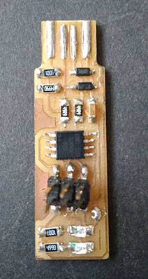
Included a ‘hero shot’ of your board
Weekly Assignment
Group Assignment
characterize the specifications of your PCB production process,
Individual assignment:
Make an in-circuit programmer by milling the PCB
Group Work
characterize the specifications of your PCB production process, i did milling of PCB and we characteristic the processes
Things i learned this week
+introduction to smd electronics components
+PCB milling on Fr1 board using 1/64 and 1/32 milling bits
+soldering SMD component on PCB board
+Testing PCB board
Goal of this week
the final achievement of this week is to make fabisp
What Is Fabisp:
the Fabisp is an in-system programmer for AVR microcontrollers, designed for production within a FabLab. It allows you to program the microcontrollers on other boards you make
Introduction to smd electronics components
Here smd stands for surface mounted device which will mount on your milled pcb board
1 Smd resistors ,A resistor is a passive two-terminal electrical component that implements electrical resistance as a circuit element. In electronic circuits, resistors are used to reduce current flow, adjust signal levels, to divide voltages, ,it have a code which is smd code written on its top we need to convert this value into ohm,learn more about smd resistor and conversion calculator you may refer
+ About smd reistance and conversion calculator
+ Video for learning how to convert this smd code into resistance value
2 Smd diode the most common function of a diode is to allow an electric current to pass in one direction (called the diode's forward direction), while blocking it in the opposite direction (the reverse direction diode is for one way transfer of current )
smd ex zener diode , led etc
Note you need to take care while fixing this component as it has positive and negative terminal polarity
3 AT tiny 44 and 45 this is AVR microcontrollers , they can control the features or actions of the product ,they are dedicated to one task and run one specific program ,it is that part which you have to program and for using this it have a data sheet which have all information about it
4 Smd capacitor Capacitor is an electronic component that stores electric charge.
5 Six pin header for programming your board through computer you need to connect your board through usb via pin which is 6 pin male and female header
Machine Modela Mdx-20
it is micro milling machine it capable of milling material such as ABS, acrylic, woods, plaster, styrene foam, chemical wood, modeling wax, and light metals such as aluminum and brass, but it could be also used for precise 3D scanning when the “Roland Active Piezo Sensor” accessory was attached
we are using it for milling copper clad / fr1 pcb board
maximum work area for this machine is 203,2 (X) x 152,4 (Y) x 60,5 (Z) mm
10W DC spindle motor that could reach a maximum revolution speed of 6500 rpm, with a tool chuck for 3.175 mm (1/8") shank diameter milling bits
PCB milling on Fr1 board
the learning phase of pcb milling begin with group assignment of milling pcb of fablab cept ,if you want your pcb to be neately printed with no use of chemical you may use this process of pcb milling ,you can find pcb milling machine in any fablab nearby your location as this machine is part of standard inventory of fablab
What is pcb miling / what is significance of pcb milling
a subtractive manufacturing process which involves the removal of areas of copper from a sheet of PCB surface in order to recreate traces for signals /current to flow in specific manner as per circuit design, When the copper is removed it facilitates electric isolation and creates the necessary ground planes and on this track you are going to fix your smd components
hat you need for pcb milling
for pcb milling you need pcb milling machine , pcb borad , scotch tape / any thin double sided tape of good quality , milling bits , brush for cleaning
As i am milling pcb for making fabisp the design i use Design of Zaerc's FabTinyStar Pcb for milling you may get that from here download design or there is also lot more detailed information available on tutorial of fabacadmy 2018
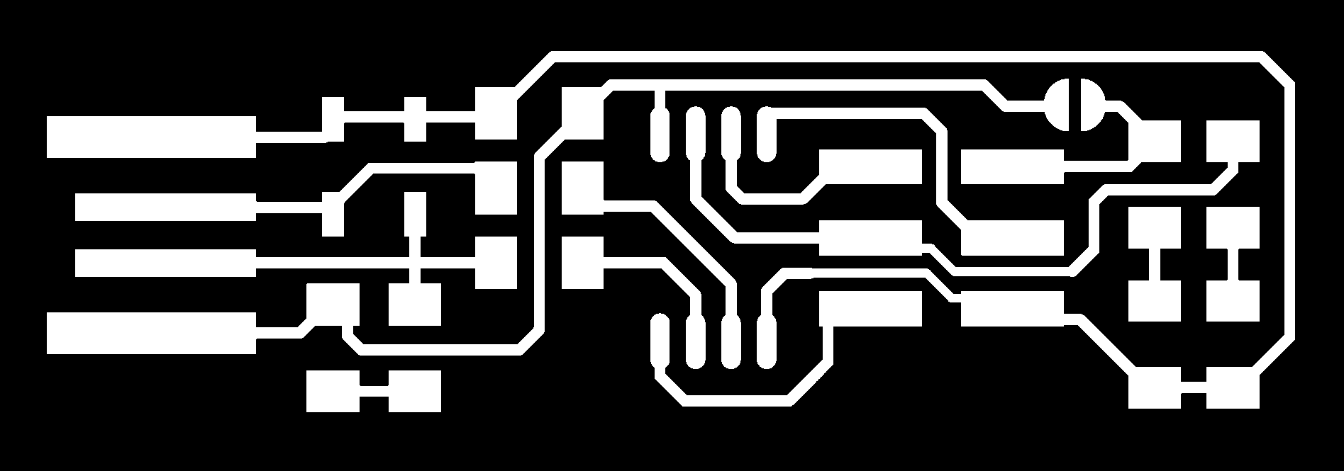
Steps for PCB milling
1 Selection of pcb board
the first step for PCB milling begin with selecting board for PCB milling you may come across fr1 and fr4 board it is recommended that to use fr1 board as it is more stronger than fr4 for more detail visit our group assignment page
2 Selection of tool
for pcb tracing we generally
use 1/64 inch bit , for pcb
cutting you may use 1/32 or
1/16 inch bit
3 Setting pcb board on the bed
you need to apply scotch tape in back of pcb and paste it at top-left corner
Fixing tool to the tool head
we are using modela mdx-20 machine for pcb milling in which you can easily attach or replace tool by using allen key
directely from tool head
4 Select image type png and machine model modela mdx-20
and click on make png
Here on the top select bit to mill trace 1/64 and speed to 2 mm/s and and zmin to -o.1mm
5 when new window open click on the load file and locate your png format file
Set the speed =2 and
z min to -0.1 and overlap =4 and click on make path rml
Once rml file is made click on send it and begin milling
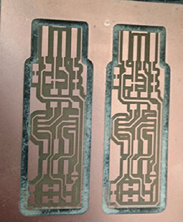
This is how your milling is going on
As i am milling 2 pcb out of this board one at offset 4 and another at offset 3 so now you need to set again the orgin at x=5 and y=25 and repeate the same step
Now set the origin for next path by clicking on move to xmin and ymin
Now generate the path for cutting process for first mill board by loading png cut file and setting cutting parameter before this you need to change bit
Click on begin milling to start the cut path before this set bit to its origin point as shown below
You need to set bit by gravity agin at this position and begin milling
Once one path of cutting is done now again set origin to x=5 and y=25 and move tool to this point and start cutting here by begin milling
This are the cutting i get from you can observe for offset 4 path is more clear
In the above i have't use sacrificial board in milling process but here i am showing you how to fix this board and use it
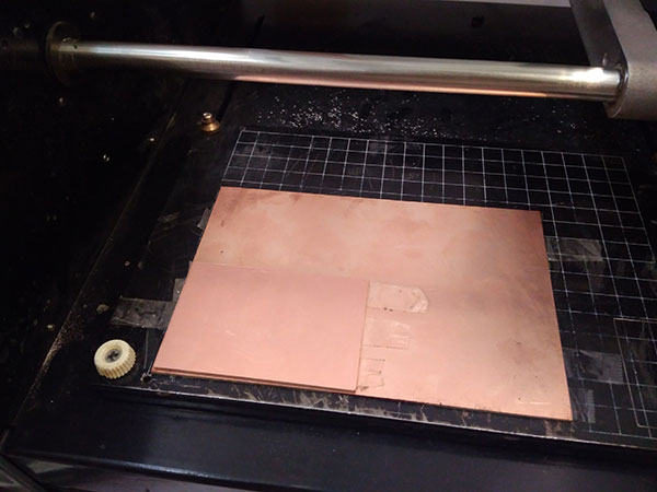
Correction in above Work
1 use sacrificial board in milling process
i have shown steps of setting sacrificial board in week 7 assignment you may refer week 7 milling page for more details
2 use online version of fabmodule
i used online version of fabmodule in week 7 while i was designing my own circuit you may refer my week 7 work for getting steps of using online version of fabmodule
Soldering Process
The next step after milling is of soldering pcb board i am making fabtiny isp so i refer a link in tutorial for soldering , before starting soldering it is recommended that you should collect all the components you need at one place and keep the isp schematic In front of you to identify the correct position of each components .
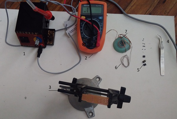
List of components
1 soldering iron
2 multimeter
3 soldering stand
4 twiser
5 smd components
6 soldering wire
7 desoldering wire
Smd Components
1x ATtiny45 or ATtiny85
2x 1kΩ resistors
2x 499Ω resistors
2x 49Ω resistors
2x 3.3v zener diodes
1x red LED
1x green LED
1x 100nF capacitor
1x 2x3 pin header
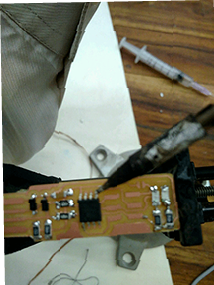
Fix the pcb board on soldering stand and start soldering by holdling component using twiser and place it on the board using schematic diagram
Note while placing component check the component polarity in case of diode , electrolyte capacitor , mosfet , transistors, battery , LED etc
Apply liquid flux on board before soldering as it will help in prevent oxidation of base and filler material as tin -lead solder attach very well to cu but poor to various oxides of cu
For soldering component you may try one more method that apply first the solder on board than heat solder and fix component on it i find difficulty in doing soldering in this way as i did one mistake as i applied solder on both side legs so it is difficult to set component over it
For next component i solder one side first than heat this to fix component than solder next side, i learn this from aditya , fabacademy fellow
Now for soldering At tiny 45, i first solder diagonally opposite legs ,this thing really help me in fixing this component
Soldering six pin header for soldering this part you need to fix it legs first in board with little solder than apply solder carefully by keeping iron in straight position
Testing and failures of this week
The boards i milled in this week and i also not able to program in all of them as some are
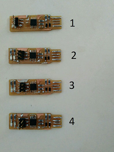
Problems with each usb
fabisb 1 - i solder wrong header on removing header track broken
fabisb 2 in which track broken while soldering as while removing extra soldering track broken failed in testing by multimeter
fabisb 3 this is alright and once programed also recognized in my laptop but when opening this in linex for testing again it won't get recognized
fabisb4 this is also right passed in multimeter testing also show green signal with avr but showing error in programing
i mill another board which is next to my four isp and repeat the same process again it work and finally programed the error with above four board is of soldering make sure you soldering is done correctely than only this is accomplished
Testing Process
For testing pcb first process is to check using multimeter for this set multimeter on continutity mode in which on touching probe a beep sound there and you also need avr isp to confirm it
Things you need to check by multimeter
1 check continuity of path /track so you are confirmed that any track is not broken
2 check nearby legs of AT tiny as many time they may get soldered with each other
Connecting your isp with avr programer if the yellow light blink it means your borad may have some problem
troubleshoot
a) check your have connected the avr header to your isp in right way i.e ground in back side
b) check your all soldering
c) check 6 pin male header pin soldering
As i connected the avr header in wrong way earlier so it is blinking yellow on changing connection it start blinking green it means it is ready for programing
Programing ISP
things you need for this
1 Avr Programer
2 linex laptop
3 your isp
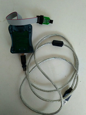
Programming fabisp
1 Plugged in the AVRISP and the FabISP into the USB slots on the PC. Connected it with the 6 pin header
2 Use these commands in sequence if you have linex in your laptop here all red code you have to write in command box step by Steps
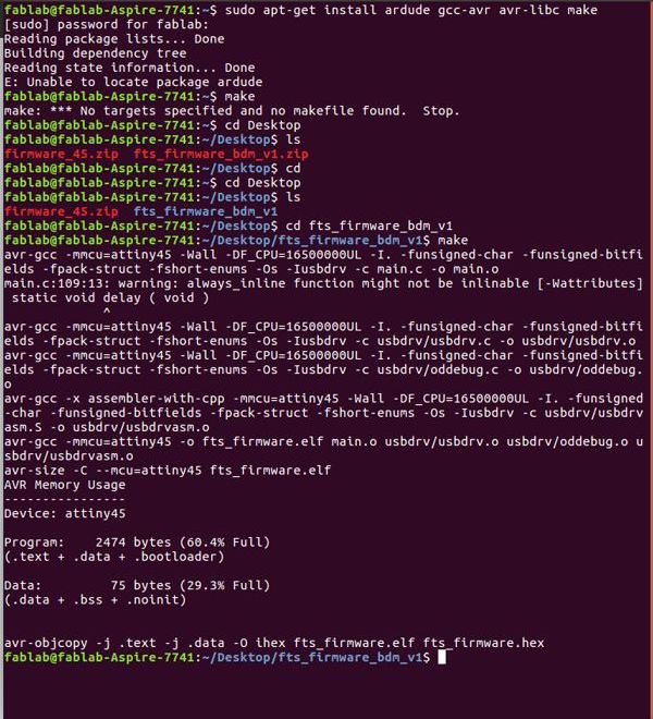
1 Open terminal
2 Type sudo apt-get install avrdude gcc-avr avr -lib make
3 Download fiirmware source code from this link extract it and copy this at desktop ( you will find file with name of firmware_45.zip
4 Now go to desktop by typing cd Desktop
5 Type ls (locate file with name fts_firmware_bdm_v1 )
6 Copy this file and type command cd fts_firmware_bdm_v1
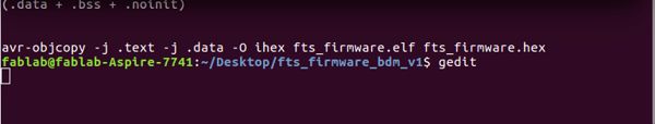
7 Type gedit a window open select make hex file and edit this file to change "programmer ?=usbtiny "to "programmer ?= avrisp "
8 Plug your board into usb port 2.0 and connect avr isp header into your board
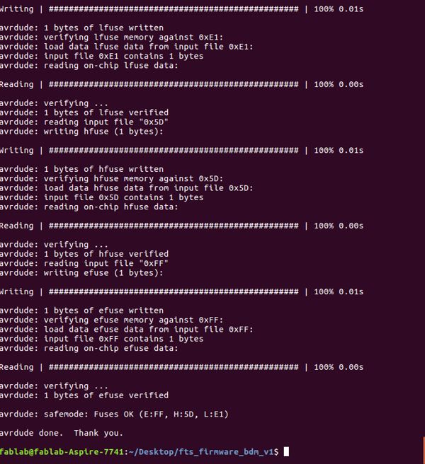
9 Type make flash this will erase the target chip program flash memory with content of the .hex file you built before
10 Type make fuse
11 Unplugh the board from usb port and disconnect the programmer than plug it back into the usb
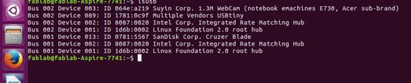
12 Type lsusb
13 See multiple vendor USBtiny this means you lsusb is recognized and it is programed
i am using this isp in week 9 for programming my board you may refer week 9 for getting More detail about using fabisp to program other board
Comparing Fabmodules (Linux), Fabomdules (online) and MODS
In this week i have used fab modules linux first to mill a pcb than i used online version , later on i explore MODS from nils recitation lecture for comparing three of them as for understanding all this three and how they are evolved one after another you Must Refer Nils recitation lecture on mods and his gitlab fabmods Repo , here i am writing summery what i learn from lecture stating from fabmodules linux version it is the first version which nils develop from kokampe and this is in form of compile c program and java script ,it was offline version which you need to download and setup in your computer it have many , it was good as it run without Internet and many fablabs in remote location used this earlier we also use this from last 2-3 years for its process Refer the steps i used in milling in top of this page , this year we were asked to use Online version of it so i made an tutorial on using fabmodules online version it is similar to offline version but have some changes in user interface as it is different , it is even better you can also milling traces overlapping in your computer also before putting your file for milling , it is compatible with Mozilla Firefox browser and Google chrome also in linux , after this nils introduce fab modes, which is light reper all it does is to patch the modules together and it runs in HTML5 UP
Limitation with fab modules
the limitation with fabmodules is that you can use it for routine but what actual happening their you can't change i.e you can use the predefines program in that but if you want to change in its workflow you can't anb in fab mods you use many modules and by editing in modules or adding or removing modules you can change or create new Workflow as per your requirement you can use this
Goal of Fab Mods
1 It is made for Rapidely compose workflow
2 Colaborate on workflow
3 To make faster computing performance and handling large amount of memory data
Explaning interface of mode
When you open fabmods click link here you were asked to right click on clicking on clicking right you get options as modules , program , edit , options .,on modules option you will find open server modules , remote server modules , open remote module we generally select open server module as here you will find many modules connecting this you can make a program as per your requirement as you finds events, files, frep , shapes ,2d ,3d , transform , view , ux , etc on clicking on any modules it open up in window and you connect many modules , edit them to create new workflow ,
in program option you will finds some programs about gear generation as this is really good tool what he wrote for making all types of gear you wll finds many programs , for machine also you can use this program as for modela , shopbot there is program so overall this is nice tool you even solidworks is also writing websockets for mods as mods .solidworks.com .
Features of mods
1 Eficient event passing
2 just in time computation
3 lots of typed array manages large blocks of memory
4 cam workflow use typed array to use giga bytes of memory and manage them easily
5 file reader allow you to bring large chucks of data
6 sockets to do messaging
7 GPU interfaces
etc.
also this is only of 60 kb all the rest is in browser so very light weight so overall this is more better than earlier fabmodules

This work by Gaurav wadhwa is licensed under a Creative Commons Attribution-NonCommercial 4.0 International License.