


Week 9
Embedded Programing
Assignment for this Week
1 Read a micro-controller data sheet
2 Program your board to do something ,with as many different programming languages and programming environments as possible
Learning from this week
1 About data sheet
2 programming board using fabisp programmer and arduino IDE
Group Work
My contribution in this of reading about various architecture and programming
Programing code
About Data sheet
Understanding Data Sheet
Datasheets are instruction manuals for electronic components. They (hopefully) explain exactly what a component does and how to use it. datasheets are still the best place to find the details you need to design a circuit or get one working
1 Purpose of using Data sheet
Data sheet are large set of data related to various specifications of component , which you may need to know and generally we focus on parameter which we are going to use for making board i.e Input and Output Pins ,Programing Pins , may be you operating component at different temperature so you need temperature range etc ,based on such factor we are looking for technical specification of micro-controller in data sheet whether it suits best for your application or not .
2 Few basic things to note while reading data sheet
Type of Architecture
Memory size
Peripheral size (Number of pins)
Special features
I/O and packages
Operating voltage
Speed grade
Industrial Temperature Range
Power consumption
3 Basic terminology
- GND means ground which is 0 volt
- Power or VCC indicates voltage.
- Current will pass when there is a voltage difference across a node
- MISO is master in slave out
- MOSI is master out slave in
- Digital pins give only 2 outcomes : "on" and "off"
- Analog related pin can give variation in voltage and not restricted to "on" and "off"
- SCK is serial clock.
- Clock - typically refers to the frequency at which a chip like a central processing unit (CPU) is running and is used as an indicator of the processor's speed.
- Operand - an input for an operation
- Processor Register - is a quickly accessible location available to a computer's central processing unit (CPU). Registers usually consist of a small amount of fast storage, although some registers have specific hardware functions, and may be read-only or write-only.
- Pipeline - pipeline is a set of data processing elements connected in series, where the output of one element is the input of the next one. The elements of a pipeline are often executed in parallel or in time-sliced fashion;
- RISC and CISC Architecture refer
- x-Bit Micro-controller where x may be 8 ,16, 32, 64 refer for difference
4 Some important source
Tutorial of how to read data sheet
https://www.sparkfun.com/tutorials/223
Data sheet of At-tiny 45
Start Reading Data Sheet
The first page is usually a summary of the part’s function and features. This is where you can quickly find a description of the part's functionality, the basic specifications (numbers that describe what a part needs and can do), and sometimes a functional block diagram that shows the internal functions of the part.
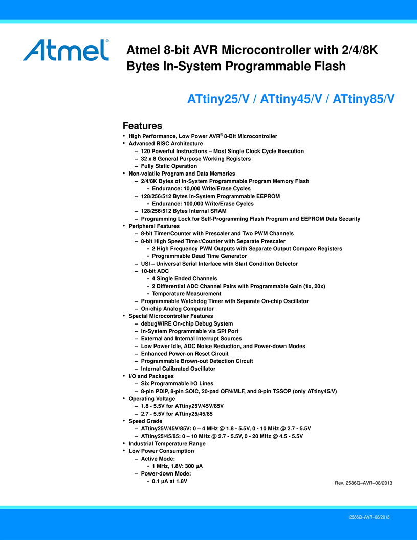
Second Page is generally pin diagram which shows which pin is dedicated to what use i use this for making simple led circuit in week 7 ,i used this as using pin diagram i assign components which i am going to use in my board to their respective position as input and output devices
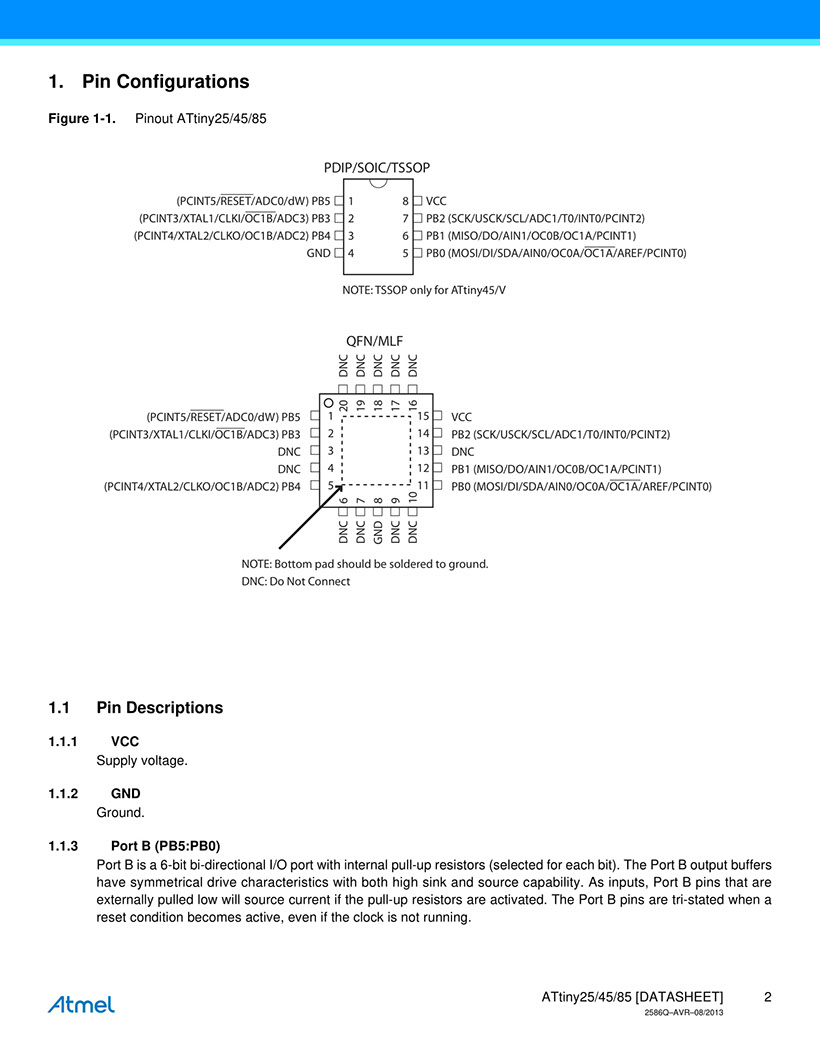
this above 2 pages are glimpse of data sheet as similar to this two pages you will find around 200-250 pages in which each page have dedicated information related to particular use of micro controller such as memory , etc we need not all information so we only look for the information we need
General Reference drawn
The high-performance, low-power Microchip 8-bit AVR RISC-based microcontroller combines 4KB ISP flash memory, 256-Byte EEPROM, 256B SRAM, 6 general purpose I/O lines, 32 general purpose working registers, one 8-bit timer/counter with compare modes, one 8-bit high speed timer/counter, USI, internal and external Interrupts, 4-channel 10-bit A/D converter, programmable watchdog timer with internal oscillator, three software selectable power saving modes, and debugWIRE for on-chip debugging. The device achieves a throughput of 20 MIPS at 20 MHz and operates between 2.7-5.5 volts.
By executing powerful instructions in a single clock cycle, the device achieves throughputs approaching 1 MIPS per MHz, balancing power consumption and processing speed.
- Parameter Name Value
- Program Memory Type Flash
- Program Memory (KB) 4
- CPU Speed (MIPS) 20
- RAM Bytes 256
- Data EEPROM (bytes) 256
- Digital Communication preripheral 1-SPI, 1-I2C
- Capture/Compare/PWM peripheral 5PWM
- Timers 2 x 8-bit
- Comparators 1
- Temperature Range (C) -40 to 85
- Operating Voltage Range (V) 1.8 to 5.5
- Pin Count 8
source -https://www.microchip.com/wwwproducts/en/ATtiny45
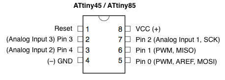
Understanding At-tiny 44
Here is a link for Attiny44 Datasheet
For understanding basic details see here
Programing board using fabisp
In this week i am using same board which i made In week 7 for programming using fabisp , i used Arduino board to program my board in week-7 where I explained steps of programming and show led blink on pressing button .I have used 2 led and button in my board which i will program using fabisp
Problem statement of programming
Green led should blink on pressing button with delay else red should blink with delay
Things you need for programming
1 fabisp
2 jumper wire
3 your board
Steps to be fellowed for Programming
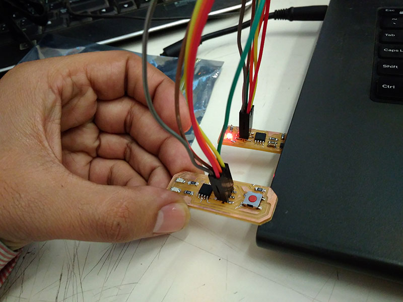
Step 1 Connect FabISP and board
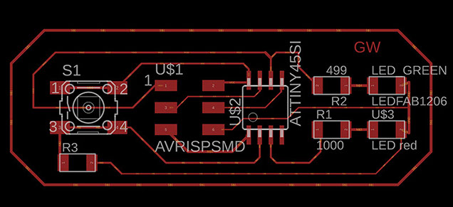
here I have to identify pin configuration and respective connections for which i connect vcc to vcc pin ,gnd to gnd pin and accordingly connect all respective pins such as reset , SCK, MISO, MOSI of ISP header to board use this two schematic board
This is a schematic of fabisp board
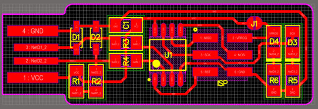
this is schematic of my board
Step 2 Program Board using Arduino as IDE and fabisp as programmer
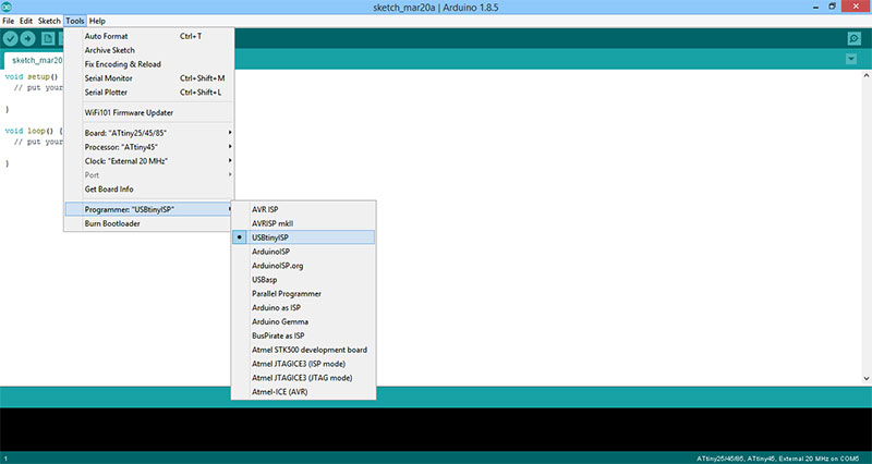
Ardiuno IDE (Integrated development environment) it is text editor and programming platform used to load program into microcontroller for programming board you have to go to tools and select
Programmer as TinyISP
Board as ATtiny 25/45/85
Processor: ATtiny 45
Clock: External 20MHZ
Step 3 Write a program to blink led as per problem statement
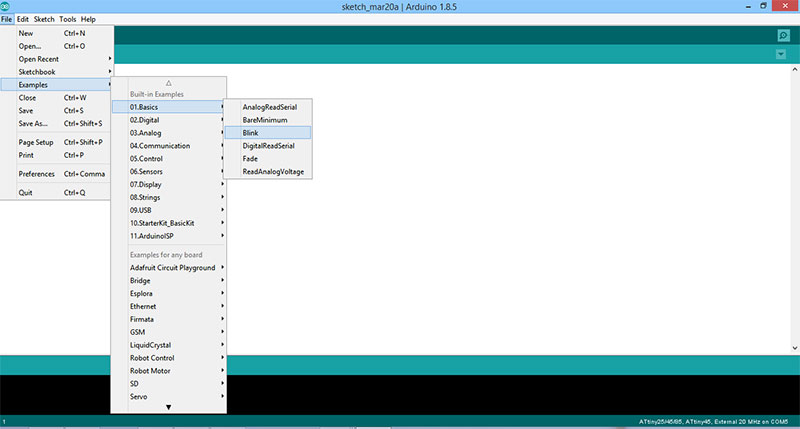
i use the blink code ( syntex avaliable in example ) and did some modification as i was easy for my as i did simillar thing in week7 where i directly program my board using arduino
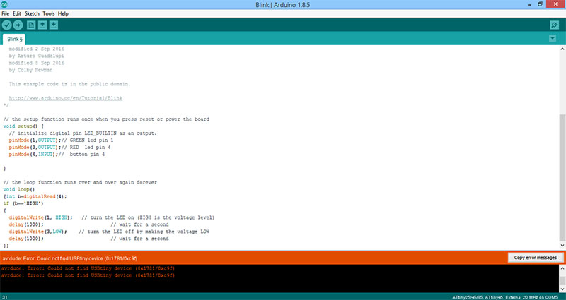
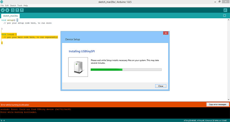
For resolving this error we need to download usbtiny isp driver here is link for downloading drivers from adafruit
I write a correct program as per problem statement give above now my board is working as per my programming code
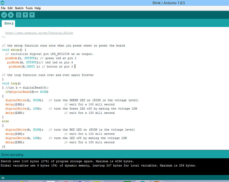
Understanding Program of this week
we understand the above code line by line
1 Void setup()- this is function in which we declare all the variable and assign them
2 // text - this is comment as compiler will not read this or this thing is only for you to add description or note
3 pin Mode (1,output) - this we use for assigning pin 1 to output mode meaning on pin 1 i can connect output devices as controller will send output signal to this pin as whatever pins of micro controller i.e between input and output pins , you are using for programming you first need to do declaration of them
4,5 , 6, 7 are similar to line 3
8 void loop() -this is the main function of program in this you write other sub function , operation , conditions , etc
9 if ( digital read (3)==High) - here digital read id function in arduino library which read value at pin 3 and "==" this is condition operands which check if value is high or low as digital signal works between high and low only
10 digital write( 1,High) this will give high signal to output pin 1
11 delay (100) this is function call to give delay of 100ms to its above code operation as here it will keep led on for 100ms
12 ,13, 14 are similar
15 else - this is part of if else loop as when if condition is not satisfied it runs else condition
16 17 18 code is similar
Understanding General Programming Codes
For understanding programing code you need to understand the basics structure of it and about the variable , functions,loops , condition , etc which we used in this ,as i have prior knowledge of c and c++ so it is easy for me to understand as in all coding languages the core comcept which we use are same as you will find all this things but yes it is scripted in different format
here are few very good source i am adding for reference for understanding
1 Computer programming basics - All the basic terminologies related to Programing
1 Arduino foundation it contains all terminologies related to what we use in program , from basic to detailed version
2 Arduino Notebook - a Pdf version download this as this is also relevant source
4 Arduino Glossery - a detailed description of everything
some definitions
1 Loop - a piece of code which keeps running until a certain condition is fulfilled - or isn't fulfilled in the case of an 'infinite loop' which will crash the system running it.
2 Function - a set of instructions which are written once to obtain a particular result, and can then be used whenever necessary by 'calling' it.
3 Variable - A way to store a piece of data which can then be modified at any time.
Working video of my board programed with fabisp
Programming the same board using Arduino , i done in week 7 , Refer week 7 for that

This work by Gaurav wadhwa is licensed under a Creative Commons Attribution-NonCommercial 4.0 International License.