I was actually very excited to use the vinyl cutter. Learning to use the vinyl cutter was very easy as there wasn’t much of software involved but just the procedure.
I decided to make a sticker for my notebook and after much contemplation, I decided to make a star wars sticker that shows the positives and negatives.
Creating Design in Photoshop
Assignment:
Individual
-Cut something using the vinyl cutter
-Use the laser cutter and document a parametric press-fit construction
-Account for laser cutter kerf
Group
-Characterize lasercutter, making test parts.
Software :
-Grasshopper
-Autocad
-Roland CutStudio
-Photoshop
Materials :
-MDF(Varying thickness)
-Vinyl sheet
Accomplised
-Explored different living hinge patterns and documented their flexibility
-Made a comb to document kerfing
-Made a parametric press-fit construction
-Explored flextures on custom design and documented the process
-Made a custom sticker on the vinyl cutter
-Worked on the group assignment to document etching and cutting parameter of different materials.
The details of the vinyl cutter used is Roland Camm servo-1 gtx-24. The machine comes with a software called Roland CutStudio. That's the software I used to cut my sticker. After importing the desired picture into the software I took the outline of the image by right-clicking and going into image outline. I set my sheet on the printer and set the origin and desired power.
Importing file into RolandCutstudio
Loading Sheet and Setting Origin
Before cutting the properties needs to be checked and the roll need to obtain sizes from the printer
Once all that was checked I started cutting the vinyl sheet. I noticed that the sheet started tearing and had to stop the cutting.
Damaged cutting & Adjusting power
Having understood that it was a power issue I corrected the power from 170 to 150. But after varying the power up to 140 the sheet kept tearing. At power 130 there were no tears but the cuts weren't deep enough as well. The result might have been due to the vinyl sheets which were very old. So I changed the roll to a recently bought one and with power at 170 proceeded with the cutting.
Loading a different sheet
Had no issues with the process this time and started with the weeding and pasting. I didn't have a transfer sheet so the process was a little challenging and time taking. I de-glued a used vinyl sheet and used it to transfer my designs.
Weeding and pasting
But the result was really good and the sticker stood out well in the black canvas.
Final Images
Laser Cutting:
The whole process of laser cutting is new to me, and having said that there are a lot of parameters that govern the laser cutting process. I was little overwhelmed when I started off as there are variables like Kerf, material quality, and thickness, power, speed etc. The actual process of using the laser cutter wasn't that complicated.
Living Hinge
After reading a little about laser cutting I decided to experiment with kerf first. I downloaded kerf templates from the link
The Following are the steps I followed in using the LaserCutter.
-Import the .dxf file into RD works.
-Check for scale and dimensions
-Switch on the cutter and most importantly the exhaust
-Check the z alignment with a pre-defined focus
-Check the origin point in the drawing and place the laser pointer in the desired location on the sheet.
-Set the necessary parameters in RD works like the speed and power.
-different lines that require different treatment can be placed in different layers where speed and power can be applied as required.
-Once all the configuration is done in RD works the drawing is then downloaded.
-In this case I used power 70 and speed as 20 (This I obtained by trial error)
-In the file menu the drawing is displayed on the cutter
-the origin is sent and then press frame
-this shoots laser on the four extreme point where the drawing is gonna be placed.
-once the desired frame is set to press start for the cutting to begin
Precautions must be taken before cutting as its very dangerous and the cutter should never be left unattended.
Cut pattern
Once the cutting process was done I started testing each hinge.
Pattern A - Very Flexible and Strong
Pattern B - Flexible but not very strong
Pattern C - Quite brittle
Pattern D - Flexible but not very strong
Fabric Pattern
These are fabric patterns that I tried and both of them were quite flexible and strong. The patterns can be used as per requirement. I decided to vary the spacing of this particular pattern to check the results. As it was similar to the most flexible pattern A
But the results were the same. The pattern was still not flexible enough
Observation:
What I learnt from this trial was that the hinge design actually varies from material to material and also the thickness of the material. For this particular material (MDF 2.5mm) Pattern, A seems to work well and the spacing and pattern co-relates with the material.
Comb
I wanted to take up MDF with a 3.5mm thickness to make my kerf kit. So in order to determine the notch size, I made a comb to check the requirements. The tooth varied from 2.0mm to 4.0mm. Made a dxf file from Auto cad and then cut it. The living hinges design was done with 2.,5 mm pine MDF hence the power was 70 and speed was 20. This time I had to resort for a cheaper MDF of 3.5mm thickness, hence the power is 40 and speed is 30
To check the sizes this I made a few samples of my press fit the shape and had them cut as well.
Test modules and comb test
The sizes fit perfectly and lock quite well. So I took up these sizes to make my modules for the press-fit Construction.
Press-fit Construction
The task was to create a press-fit construction using parametric design. I decided to use grasshopper for this purpose. Learning grasshopper was very challenging. The basics tools were easy but the advance operations were difficult to follow as there are so many tools, and function to learn. I started looking at tutorial form grasshopper website itself.
All his works were really inspirational and innovative. Inspired by one of his designs I decided to make my own based on that.
I made my desired shape in Cad and then imported the shape in rhino. The basic idea of the grasshopper function is to take a notch that's already constructed and place in the geometry.
Imported desired shape in Rhino
The first process is to explore the geometry and then identify its midpoint to the notch can be placed there, once placed the notch orientation need to be adjusted to suits our needs. The placed notch needs to be cut from the main geometry.
The notch is set as a curve
Geometry is assigned
Now the notch is assigned and the geometry is assigned. The task now is to it attach the geometry to the desired midpoints.
Notch attached to Geometry
Now its time to cut the geometry and using the bounding box to replicate the geometry in XY directions to the desired number. This is how it looked.
Replicating the Geometry in XY
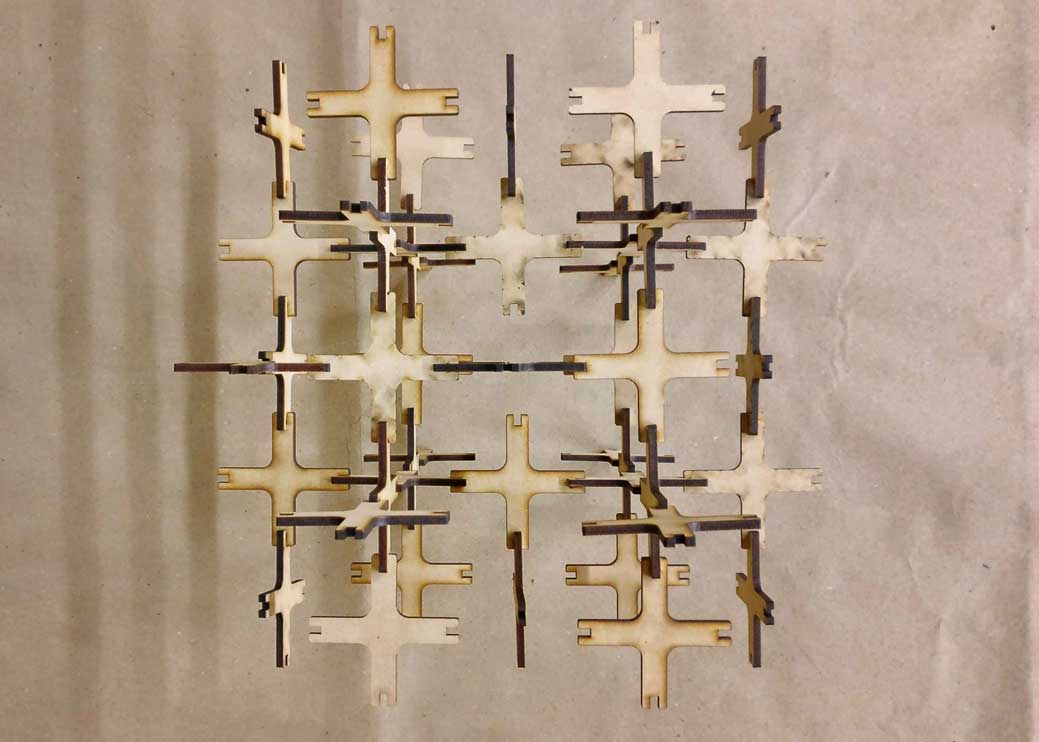
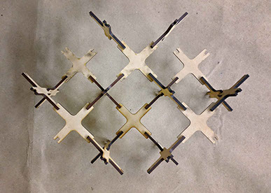
The Complete module
But sending this to print will result in a lot of material wastage so I rearranged the elements and sent a few for a test cut.
First test cut
This was the result. The curve along the edges was not correct and was quite confused as to why. The display on RD works also reflected the same kind of problem. On discussing with my instructor regarding the same, I understood that RD works may not see the files as rhino perceives it. The nurb curves were the problem. So while exporting it's necessary to export with line and arcs.
Exporting from Rhino
I exported using this and the result was as desired. So I went to cut all the pieces.
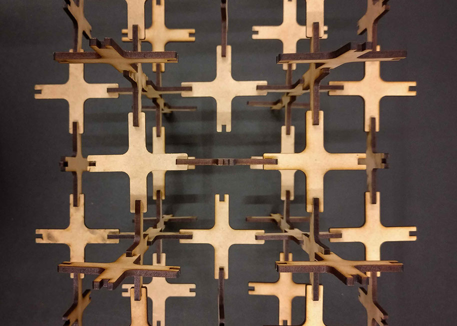
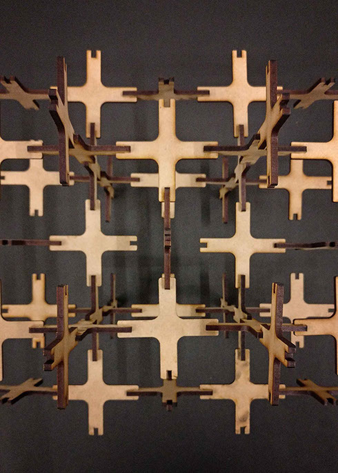
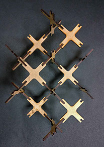
Final Cutting Process
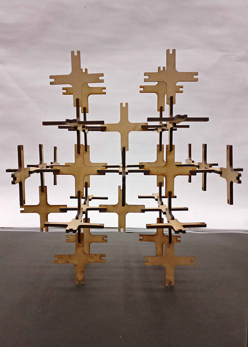
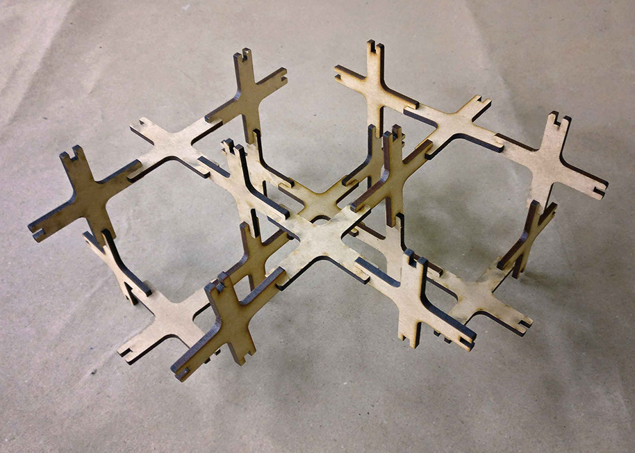
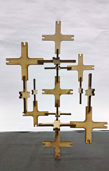
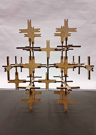
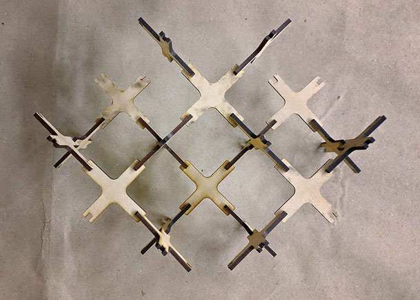
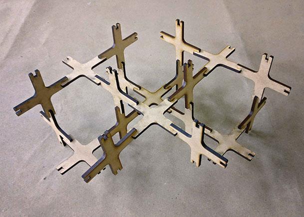
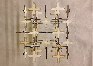
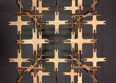
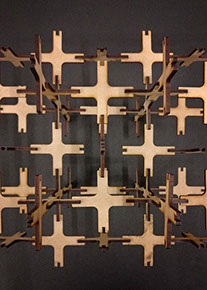
Once all the piece were cut I started assembling to form a shape and here are the results.
I wanted to combine the press fit and flextures to form a fabric like model. As I had experimented earlier I wanted to go with the geodesic pattern for this and so chose hexagon as my base piece.
To begin with, I didn't know the exact kerfing that's required to make it work and so I began experimenting.
My first attempt was with 3.5 mm MDF with 2mm spacing between lines. I designed all this in Autocad as it is a software I already knew and was easy to experiment all of it in that.
I was happy with the size and look of the design but the design was not flexible. The reason was the thickness of the material. So this time attempts with 2.5mm MDF. The result was the same, The material was not flexible,.
On my third attempt, I made changes to kerfing. Instead of lines, I made notches. That created better movement and one important observation is that when flexed the entire stress was in the center of the hexagon resulting in fracture of some of the pieces. So this time I modified the design slightly on account of this.
Design after 3 Iterations
The result was great. The pieces looked better and were quite flexible as well. So I went on printed a couple of more pieces with the same design and to lock them had a small H shaped piece.
Once I was satisfied with the modules I went on to print it on large amounts to make a faric like pattern.
The whole process was time consuming and took about 1hr45mins to print the entire design for a 2.5mm thick MDF board with 30 power and 20 speed.The size of the modules were small so putting them together was really a test of patients.
Once completed this is how it looked
I started testing the model for flexibility and what I noticed was that the whole curvature of the module was not entirely because of the kerfing alone but also because of the hinges.
Testing for flexibility and stress
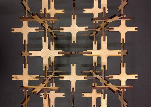
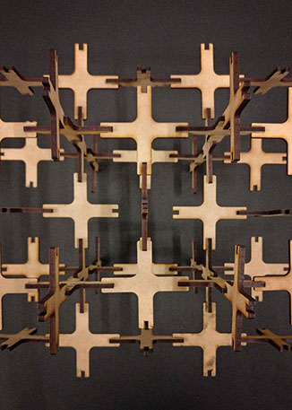
To test the approximate ratio of actual flexture I printed out the same module without kerfing and compared the two for flexibility.
Without Kerf
With Kerf
From the above comparison its understood that about 40% of the flecture is because of the hinges. The way to improve this design is to change the type of joinery or to find another solution to fix each piece together. Yet I was happy how the whole learning process turned out to be. With the help of my instructor modifications were done to the module and the joinery to make it more efficient and here are the results.
Revised module and joinery
Now I'm able to form a complete sphere after making modifications. By doing this model what I learned was about flextures and kerfing. After many iterations, I came to a final design that worked for my model. Another major point to be kept in mind while doing kerf for a particular design is that the stress points or the points where its most likely to fracture must be noted and the grooving must be given accordingly. So to sum up, the spacing and type grooving must be decided on the type and thickness of the material.The fracture points must be noted and the grooves must be designed accordingly.
Once this is done, keeping the final model in mind the joints or the connecting members must be designed accordingly.
The idea was to create a palette of different cutting and etching parameters for different materials. As we are part of a college campus we wanted to create a reference card for each material, which would help the students to get an exact idea of the parameters that needs to be used in order to achieve the desired result.
I took up the designing part of the card. I used Auto cad to create the card and assigned different layer types, so assigning different power and speed would become easy.
One side of the card explains the material and its thickness, while the other different parameters. In cutting the power is kept constant and in etching the speed is constant.
Files
All Files can be downloaded from the following link
This week is about computer-controlled cutting. The basic idea is to use cutting tools such as laser cutter and vinyl cutter, learn how to use them and also their parameters. In the lecture, Neil spoke about different types of cutters like wire cutter, plasma etc. This week is also combining last weeks assignment I.e cutting using parametric design. Neil then spoke about different types of lasers and most importantly safety aspects while using a laser cutter.