What is an Output Device?


Output devices in electronic systems transfer energy from the electrical energy that has been processed to another kind of energy, often light, sound or movement (kinetic). Output devices can be digital or analogue.

Devices which perform an “Output” function are generally called Actuators.


Assignment:

Individual

- Add an output device to a microcontroller board you've designed, and program it to do something


Group

-Measure the power consumption of an output device


Software :

-Eagle

-Mods

-Arduino IDE


Materials :

-FR1

-Eelectronic Components


Accomplised


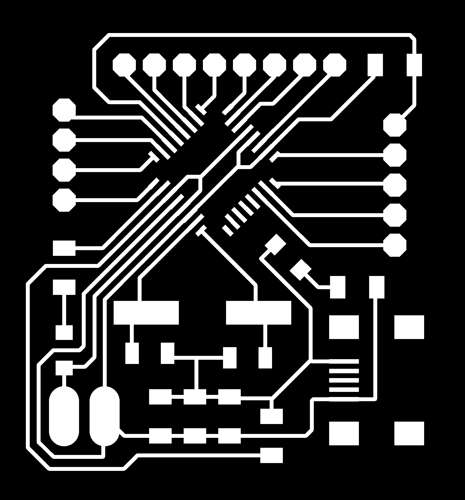
-Designed, Milled and Programmed a Modular board

-Understood the connections of the same

-Designed, Milled a LED array Shield

-Used Led array as an output device

-Used Stepper Motor as an output device


Group Work


Download Files

The above gif is 3d printed stepper motor, which is an output device. Reading about it in the following link and how to make it.

HeatBot


An immersive experience introducing a next-generation chatbot.Using Facebook Messenger as an interface, HeatBot asks visitors a few questions about how they’re feeling. Linked to a chatbot with eight core emotions and over 1,000 responses, HeatBot then engages visitors through a stream of personalized photos, GIFs and sounds, while simultaneously displaying a glowing, colorful emotional response on a 42” x 42” LED matrix panel. Users are sent away with a GIF and static image of themselves inside to share.

Modular Board

Electronics was completely a new subject for me when I joined fab academy. So when I heard about Arduino, Satshakit and Raspberry Pi I really didn't know what to make of them. For my final project, I could simply design a board with the needed input and output pins or make a modular board like the satshakit which could be used for multiple purposes. Having come this far, I wanted to give it a try. To design my own modular board. So I started going through various profiles in Fab Academy and the satshakit to understand the design first. The following are the reference links that I used.


Reference:

https://github.com/satshas/satshakit

http://fabacademy.org/archives/2015/doc/projects/fabkit-0.4.html

http://fabacademy.org/archives/2015/eu/students/ingrassia.daniele/

http://archive.fabacademy.org/archives/2017/fablabcept/students/184/week-6_-electronics_design.html\

https://github.com/satshakit/satshakit-M7

http://fab.academany.org/2018/labs/fablabcept/students/tanvir-khorajiya/week-11.html

Having understood the basics of it I took it to Eagle and started designing. The fab kit uses atmega168, whereas satshakit uses Atmega 328p. My lab had the availability of 328p and is better than 168, so I decided to use 328.


Specification of Atmega 328P


The Atmel 8-bit AVR RISC-based microcontroller combines 32 kB ISP flash memory with read-while-write capabilities, 1 kB EEPROM, 2 kB SRAM, 23 general purpose I/O lines, 32 general purpose working registers, three flexible timer/counters with compare modes, internal and external interrupts, serial programmable USART, a byte-oriented 2-wire serial interface, SPI serial port, 6-channel 10-bit A/D converter (8-channels in TQFP and QFN/MLF packages), programmable watchdog timer with internal oscillator, and five software selectable power saving modes. The device operates between 1.8-5.5 volts. The device achieves throughput approaching 1 MIPS per MHz.

The Following are the components that I needed to design my board:


Components List


1x ATMega 328p

1x 10kΩ resistor

1x 499Ω resistor

1x 1kΩ resistor

1x 1uF Capacitor

2x 22pF Capacitor

1x Red LED

1x Blue LED

1x 16Mhz Crystal

1x Micro USB Conenctor

I wanted to keep the pins on one side with the power option on the other. Also made sure all the serial communication pins are close to each other so while programming it's easy.

Components and Names

Board

To make sure all my designs are as planned I made sure not to use the auto-route command. I manually routed the board and placed the components as desired.

Components and Names

Once I was done with designing I checked the layout again and made the trace, drill and cut file using Krita. To know the process please click here

Trace, Drill and Cut

Opened up Fabmodules and imported the trace file.It's important to check the file for any overlap before milling. A lot of times overlapping happens and the milled board is of little to no use. As expected there was some overlap, but then it was not in the routing but in the pads of the MCU. I used Krita again to correct this problem.

Overlap

Overlap Corrected

Once all the corrections were sorted out I milled my board. The traces were fine, but there were some traces that were too thin, but that was not because of the design but because of the Roland machine. The machine has not been maintained properly, so been having trouble with the milling process lately.

Milled Board

I then soldered all the components on the board. Soldering the Atmega 328P was not at all easy. The pins were very small. I did make a mess trying to solder the MCU. Also, all other components are closely packed to make the boards small. So soldering was a challenge. This is my soldered board.

Soldered Board

I tried Programing the board, but I failed and wasn’t able to upload the bootloader. I checked my drawing and started experimenting on the board by removing and altering the components to check what went wrong. One important mistake was that I had connected the capacitor from VCC to VCC

Error in Design

Having found the problem, I desoldered and tried programming it again, but failed. I still wasn't sure what the problem was. So I started looking answers when I came across satshakit micro. The design was almost similar to what I had in mind, yet the major difference was the number and value of capacitors in the circuit. I am not sure why so many capacitors are required. I anyhow decided to use the satshakit micro scheme to modify my board. Added a couple of resistors in my scheme and corrected the previously diagnosed problems.

Redesigning

The following is the revised Component list.


Component List


1x ATMega 328p

1x 10kΩ resistor

1x 499Ω resistor

1x 1kΩ resistor

1x 0Ω resistors

1x 1uF Capacitor

1x 10uF Capacitor

1x 100nF Capacitor

2x 22pF Capacitor

1x Red LED

1x Blue LED

1x 16Mhz Crystal

1x Micro USB Conenctor

Board File

Again made trace drill and cut files.

Trace, Drill and Cut

Checked fab modules for overlap and milled the board.

FabModules

The traces were fine and the board wasn’t much bigger than what it was. I was happy how it looked as an end design.

Milled Board

I soldered all the components and even powered it up to see if the Power led was glowing.

Soldered Board

Now for the final test. To see if this board is working. I used Arduino to program by the board.


The following picture explains the pinout from Arduino Uno to my board.

Arduino Pin Connection

And yes !!! I was able to burn the bootloader this time without any problem at all. It was great that the board was working. I also wanted to test if I could upload any program. So I decided to upload a blink code. My another led was connected to the 4th pin. I modified the blink program accordingly and uploaded, but was unsuccessful in uploading.

Unable to Upload

I wasn't sure what the problem. With the help of a friend, I realized that the program needs to be uploaded as a programmer. Shortcut key Shift + Ctrl + U. This worked like a charm and the blink program was uploaded.

Extremely happy and satisfied with having designed and produced a modular board.

Output Devices

Since in my final project I require something close to a LED array, I decided to make one. The problem was I cannot use Neil's design as is because I need to redesign it as a shield so I can use it on my board. Understanding the connection of Charlieplexing wasn't easy. I used reference from the following link to draw my scheme.

http://fab.cba.mit.edu/classes/863.11/people/theodora.vardouli/09_Output/09.html

Components required to design LED array board


Component List


3x 499Ω resistor

9x 0Ω resistor

6x White LED

3x Yellow LED

LED array Scheme

I pulled out 3 pins from the circuit to connect to my board.

Board File

Once the design was done made trace, drill and cut file and took it to fabmodules.

Board File

FabModules

The board was smaller than I expected it to be. However, the traces were fine.

Milled Board

Soldering the components was not at all easy. The board was so tiny and required a lot of patience.

Soldered Board

Once the soldering process was done, I first need to program my board. This time I used My FabISP to program my modular board. The picture explains the pin connections for the same.

Pinout

I still haven't understood the concept of Charlieplexing completely. I didn't know how the system works. However, I checked the board with multi-meter to see if the connections are right and the LED's lit up. My board has 3x3 LEDs. Whereas Neil's program is for 4x5 LEDs. It was quite difficult to follow his code as well, hence I searched the internet to find similar kind of codes. I didn't find exactly what I wanted but kinda close to it. The following are the link for the same:

http://www.instructables.com/id/Charlieplexing-the-Arduino/

https://gist.github.com/StuffAndyMakes/5583969

https://www.stuffandymakes.com/blog/2015/4/28/charlieplexing-more-leds-20-to-be-exact

I found these codes quite hard to follow as well. Anyhow, I modified them by changing the number of pins and the pin inputs. I then connected my board with the LED array board

Pinout

I was successful in uploading the program, but the output was not as desired. The LED's were working only in the first two row and columns. I tried several other programs and yet failed.

Possible reasons for failure.


1.Wrong shield design

2.Possible connection error

3.Wrong program.

Since there is no exact reference to what I want, I need to study Charlieplexing properly and try redesigning the board.


Servo Motor


Anyhow to check an output device with my board I used a servo motor and ran it with a simple sweep code, that is available in the example programs of the Arduino software.


The servo motor is usually a simple DC motor controlled for specific angular rotation with the help of additional servomechanism (a typical closed-loop feedback control system). Now day’s servo system has large industrial applications.

The main reason behind using a servo is that it provides angular precision, i.e. it will only rotate as much as we want and then stop and wait for next signal to take further action. The servo motor is unlike a standard electric motor which starts turning as when we apply power to it, and the rotation continues until we switch off the power.


Since I'm going to use a servo as my output device there are certain conditions that I need to know in order to connect and program them. I am using an Atmega 328P to control the servo and reading the datasheet for the same is necessary.


The first configuration that needs to be checked in the microcontroller is the timer.

Timer


So basically, a timer is a register! But not a normal one. The value of this register increases/decreases automatically. In AVR, timers are of two types: 8-bit and 16-bit timers. This means that the 8-bit timer is capable of counting 2^8=256 steps from 0 to 255 as demonstrated below.

Similarly, a 16-bit timer is capable of counting 2^16=65536 steps from 0 to 65535. Due to this feature, timers are also known as counters. Now, what happens once they reach their MAX? Does the program stop executing? Well, the answer is quite simple. It returns to its initial value of zero. We say that the timer/counter overflows.


In ATMEGA328, we have three different kinds of timers:

TIMER0 – 8-bit timer

TIMER1 – 16-bit timer

TIMER2 – 8-bit timer

The best part is that the timer is totally independent of the CPU. Thus, it runs parallel to the CPU and there is no CPU’s intervention, which makes the timer quite accurate.


Apart from normal operation, these three timers can be either operated in normal mode, CTC mode or PWM mode. We will discuss them one by one.

Timer Concepts


Since childhood, we have been coming across the following formula:

Now suppose, we need to flash an LED every 10 ms. This implies that its frequency is 1/10ms = 100 Hz. Now let's assume that we have an external crystal XTAL of 4 MHz. Hence, the CPU clock frequency is 4 MHz. Now, as I said that the timer counts from 0 to TOP. For an 8-bit timer, it counts from 0 to 255 whereas for a 16-bit timer it counts from 0 to 65535. After that, they overflow. This value changes at every clock pulse.


Let’s say the timer’s value is zero now. To go from 0 to 1, it takes one clock pulse. To go from 1 to 2, it takes another clock pulse. To go from 2 to 3, it takes one more clock pulse. And so on. For F_CPU = 4 MHz, time period T = 1/4M = 0.00025 ms. Thus for every transition (0 to 1, 1 to 2, etc), it takes only 0.00025 ms!

Now, as stated above, we need a delay of 10 ms. This may be a very short delay, but for the microcontroller which has a resolution of 0.00025 ms, it's quite a long delay! To get an idea of how long it takes, let's calculate the timer count from the following formula:

Substitute Required Delay = 10 ms and Clock Time Period = 0.00025 ms, and you get Timer Count = 39999. Can you imagine that? The clock has already ticked 39999 times to give a delay of only 10 ms!

Now, to achieve this, we definitely cannot use an 8-bit timer (as it has an upper limit of 255, after which it overflows). Hence, we use a 16-bit timer (which is capable of counting up to 65535) to achieve this delay.

Timer Register


You can change the Timer behavior through the timer register.  The most important timer registers are:


TCCRx - Timer/Counter Control Register. The prescaler can be configured here.

TCNTx - Timer/Counter Register. The actual timer value is stored here.

OCRx - Output Compare Register

ICRx - Input Capture Register (only for 16bit timer)

TIMSKx - Timer/Counter Interrupt Mask Register. To enable/disable timer interrupts.

TIFRx - Timer/Counter Interrupt Flag Register. Indicates a pending timer interrupt.


Prescaler


The pre-scaler divides the system clock by a fixed amount, usually a binary fraction so that the timer itself can be incremented at a slower rate and thus cover a longer interval before it overflows and rolls over. The prescaler can be set to 8, 64, 256 or 1024 compared to the system clock.

The trade-off for covering a longer interval is that you can no longer resolve very short intervals.

Clock select and timer frequency


Different clock sources can be selected for each timer independently. To calculate the timer frequency (for example 2Hz using Timer1) you will need:

1. CPU frequency 16Mhz for Arduino

2. maximum timer counter value (256 for 8bit, 65536 for 16bit timer)

3. Divide CPU frequency through the chosen pre-scaler (16000000 / 256 = 62500)

4. Divide result through the desired frequency (62500 / 2Hz = 31250)

5. Verify the result against the maximum timer counter value (31250 < 65536 success) if fail, choose bigger pre-scaler.

Interrupts


Well, this is not exclusively related to timers, but I thought of discussing it as it is used in a variety of places. Let me explain it using an analogy. Say now you are reading my post. It's dinner time and your mom (only if you live with your mom ;)) calls you for dinner. What do you do (if she gets too creepy)? You save your work and attend to your mom's call, then return and resume reading. This is an example of an interrupt.


In most microcontrollers, there is something called interrupt. This interrupt can be fired whenever certain conditions are met. Now whenever an interrupt is fired, the AVR stops and saves its execution of the main routine,  attends to the interrupt call (by executing a special routine, called the Interrupt Service Routine, ISR) and once it is done with it, returns to the main routine and continues executing it.


For example, in the condition of counter overflow, we can set up a bit to fire an interrupt whenever an overflow occurs. Now, during execution of the program, whenever an overflow occurs, an interrupt is fired and the CPU attends to the corresponding ISR. Now it’s up to us what do we want to do inside the ISR. We can toggle the value of a pin, or increment a counter, etc etc.

Code


To explain all this in coding I have taken Neil's Servo code

//

// hello.servo.44.c

//

// servo motor hello-world

//

// set lfuse to 0x5E for 20 MHz xtal

//

// Neil Gershenfeld

// 4/8/12

//

// (c) Massachusetts Institute of Technology 2012

// This work may be reproduced, modified, distributed,

// performed, and displayed for any purpose. Copyright is

// retained and must be preserved. The work is provided

// as is; no warranty is provided, and users accept all

// liability.

//


#include <avr/io.h>

#include <util/delay.h>


#define output(directions,pin) (directions |= pin) // set port direction for output

#define set(port,pin) (port |= pin) // set port pin

#define clear(port,pin) (port &= (~pin)) // clear port pin

#define pin_test(pins,pin) (pins & pin) // test for port pin

#define bit_test(byte,bit) (byte & (1 << bit)) // test for bit set

#define position_delay() _delay_ms(1000)


#define PWM_port PORTA

#define PWM_pin (1 << PA6)

#define PWM_direction DDRA


int main(void) {

   //

   // main

   //

   // set clock divider to /1

   //

  CLKPR = (1 << CLKPCE);

   CLKPR = (0 << CLKPS3) | (0 << CLKPS2) | (0 << CLKPS1) | (0 << CLKPS0);

   //

   // set up timer 1

   //

   TCCR1A = (1 << COM1A1) | (0 << COM1A0); // clear OC1A on compare match

   TCCR1B = (0 << CS12) | (1 << CS11) | (0 << CS10) | (1 << WGM13); // prescaler /8, phase and frequency correct PWM, ICR1 TOP

   ICR1 = 25000; // 20 ms frequency

   //

   // set PWM pin to output

   //

   clear(PWM_port, PWM_pin);

   output(PWM_direction, PWM_pin);

   //

   // main loop

   //

   while (1) {

      //

      // 1 ms PWM on time

      //

      OCR1A = 1250;

      position_delay();

      //

      // 1.5 ms PWM on time

      //

      OCR1A = 1875;

      position_delay();

      //

      // 2 ms PWM on time

      //

      OCR1A = 2500;

      position_delay();

      }

   }


The highlighted portions of the code talk about timer and clock setting. Note that this is for Attiny44 controller.

The CLKPR is the clock prescaler and in this case its 0,0,0,0 which means its at default and no prescaling is done.

TCCR1A & TCCR1B are different TIMER 1 registers.

OCR1A is again a register for TIMER1 that in this case controls the delay of the servo.


In Arduino programming, the servo uses a library called servo.h. All the timer configurations are taken care of by the library hence the coding becomes very simple. Since I use Arduino for my programming I Just have to call the library and used the functions therein.

https://www.robotshop.com/letsmakerobots/arduino-101-timers-and-interrupts

https://oscarliang.com/arduino-timer-and-interrupt-tutorial/

https://playground.arduino.cc/ComponentLib/Servotimer1

Programming

Code


#include <Servo.h>


Servo myservo;  // create servo object to control a servo

// twelve servo objects can be created on most boards


int pos = 0;    // variable to store the servo position


void setup() {

  myservo.attach(13);  // attaches the servo on pin 13 to the servo object

}


void loop() {

  for (pos = 0; pos <= 180; pos += 1) { // goes from 0 degrees to 180 degrees

    // in steps of 1 degree

    myservo.write(pos);              // tell servo to go to position in variable 'pos'

    delay(15);                       // waits 15ms for the servo to reach the position

  }

  for (pos = 180; pos >= 0; pos -= 1) { // goes from 180 degrees to 0 degrees

    myservo.write(pos);              // tell servo to go to position in variable 'pos'

    delay(15);                       // waits 15ms for the servo to reach the position

  }

}

Week 12 Group Work:


The assignment was to measure the power consumption of an output device. As done earlier we decided to connect a DC motor to the oscilloscope. The motor was connected to the power jack. My contribution was to read about the connections and how to configure the oscilloscope to read the values from the motor.

Conclusion


The week's assignment was quite straightforward, but things got interesting and difficult because I wanted to make a modular board. As I said earlier, this is something that was far-fetched, before I started this course and it gave me a great sense of satisfaction to have actually designed and produced a modular board. This week, however, gave me a clearer picture of how I need to go about the electronics part of my project. There are still certain things in electronics that I am unable to understand or why they have to be done in a certain way. Probably in time, I will understand them.

Files


All files can be downloaded from HERE


WEEK 12

Output devices.These are components that interface with the physical world (such as a motor or light bulb), or drives a device which interfaces with the outside world. Neil started the lecture by explaining the safety factors and then went on to explain the different type of output devices and their connections. The last part of the lecture was on how output devices are used in projects.