Task:
Propose a final project masterpiece that integrates the range of units covered.
Your project should incorporate:
- 2D and 3D design
- additive and subtractive fabrication processes
- electronics design and production
- embedded microcontroller interfacing and programming
- system integration and packaging
Where possible, you should make rather than buy
the parts of your project
What will it do?
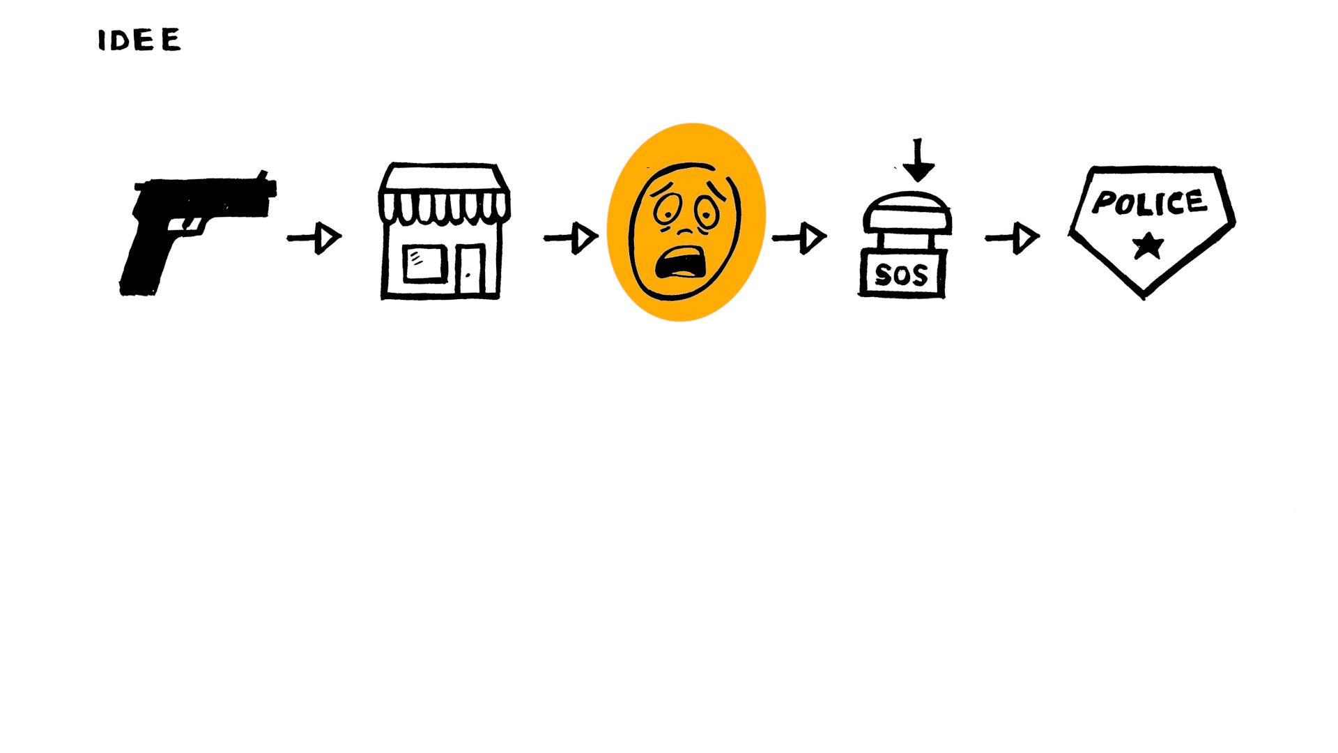
A emergency notification system
This device triggers an alarm and notifies other people or the police by e-mail.
It is a help! button for personal protection as part of a prevention system.
I decide to do this project after some family members experienced robbery or kidnapping. This security system should be low-cost, easy to make/use and independent/open source.
Who's done what beforehand?
After searching for some references in the Fab Academy site, I did not find a personal alarm device. I find a project that does something similar, but for tracking patients.
Alarm system track patient condition: ATtiny44, Wifi, App
I also found other tutorials about safety devices or emergency systems:
 @instructables_JeanotP1314_emergencybutton
What systems will be made?
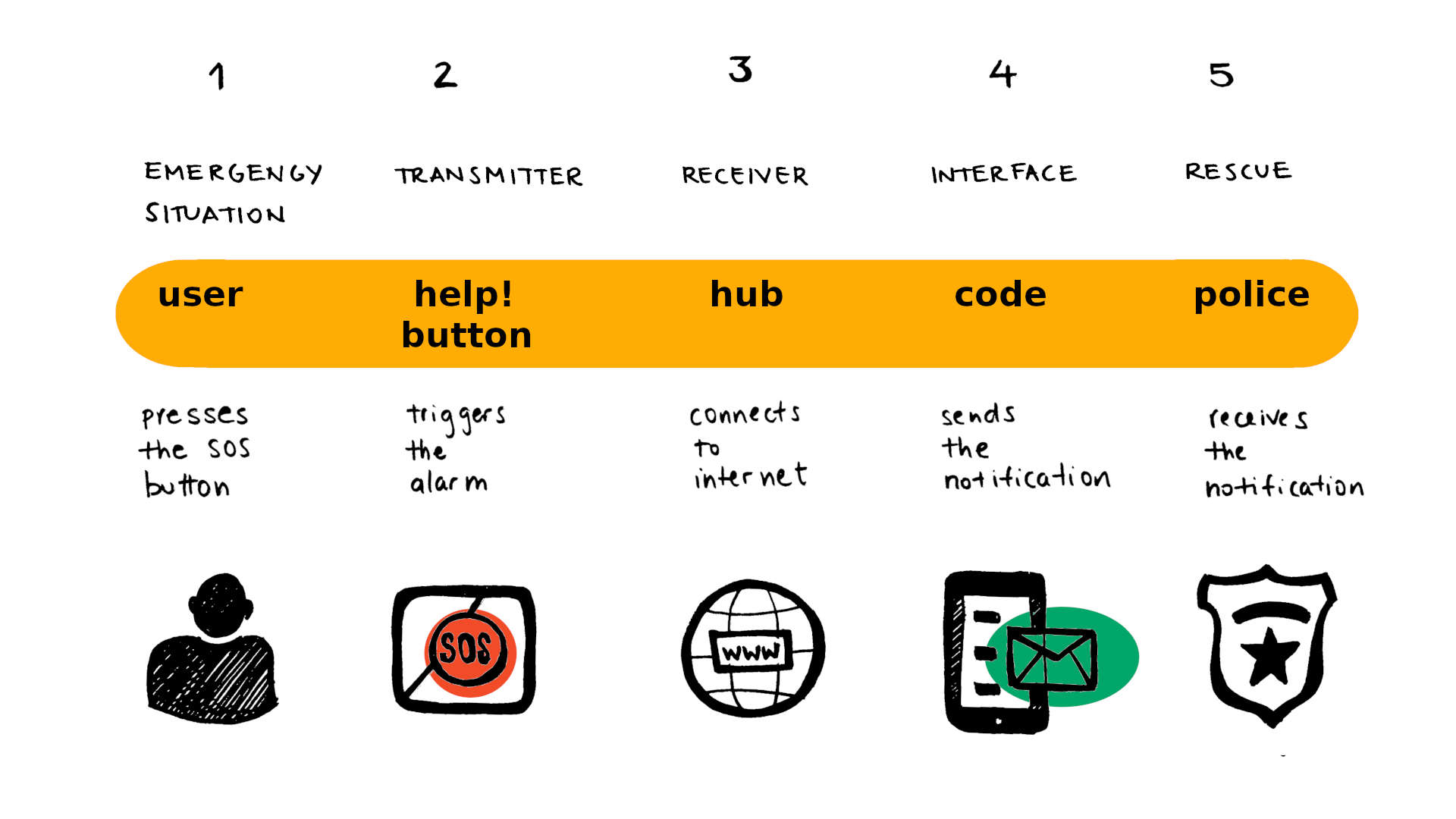
The emergency notification system consists of three parts:
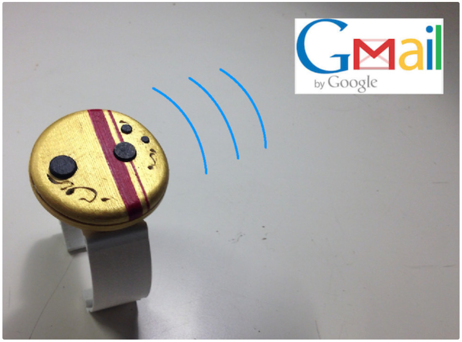
(1) The transmitter: with the help button. It triggers the alarm.
(2) The receiver: the hub with WiFi connectivity. It accesses the internet.
(3) The interface application: it sends the emergency notification.
Update: An interface is not required. The mail is sent directly from the hub (ESP32).
 Concept
What materials and components will be used?
MATERIALS:
- Electronic components (→ list)
- PLA filament (3D printer)
- Acrylic (Laser cutter)
- Adhesive vinyl for labeling (Vinyl cutter)
COMPONENTS:
- State button to trigger the notification
- State button to reset and boot
- Pinheads and DC connector
- LED: green, red and blue
- Resistors, capacitors, schottky diode and voltage regulator
- Microcontroller: ATmega328 and ESP32-WROOM (WiFi)
- Power supply: Batteries, battery holder, Plug-In power supply
- Transmitter and receiver: RF 433 MHz
- OLED display
- Circuit board
Where will come from?
The components and materials I need I will order from suppliers like Farnell, DigiKey or Reichelt. Many of the components are available in the Fab Lab such as the FR4 prototyping board. In the list below are the links to order the components, click on Part Number.
How much will they cost?
Board 1
Here is the BOM for first board. I ordered the most of the components from Germany. The first board should cost about 8,90€. Add to this the cost of the batteries, the prototyping board and the use of the CNC machine.
Board 2
Here is the parts list for the second board. This board should cost about 19 €. In addition, there are costs for the batteries, the prototyping board and the use of the CNC machine.
What parts will be made? What will you design?
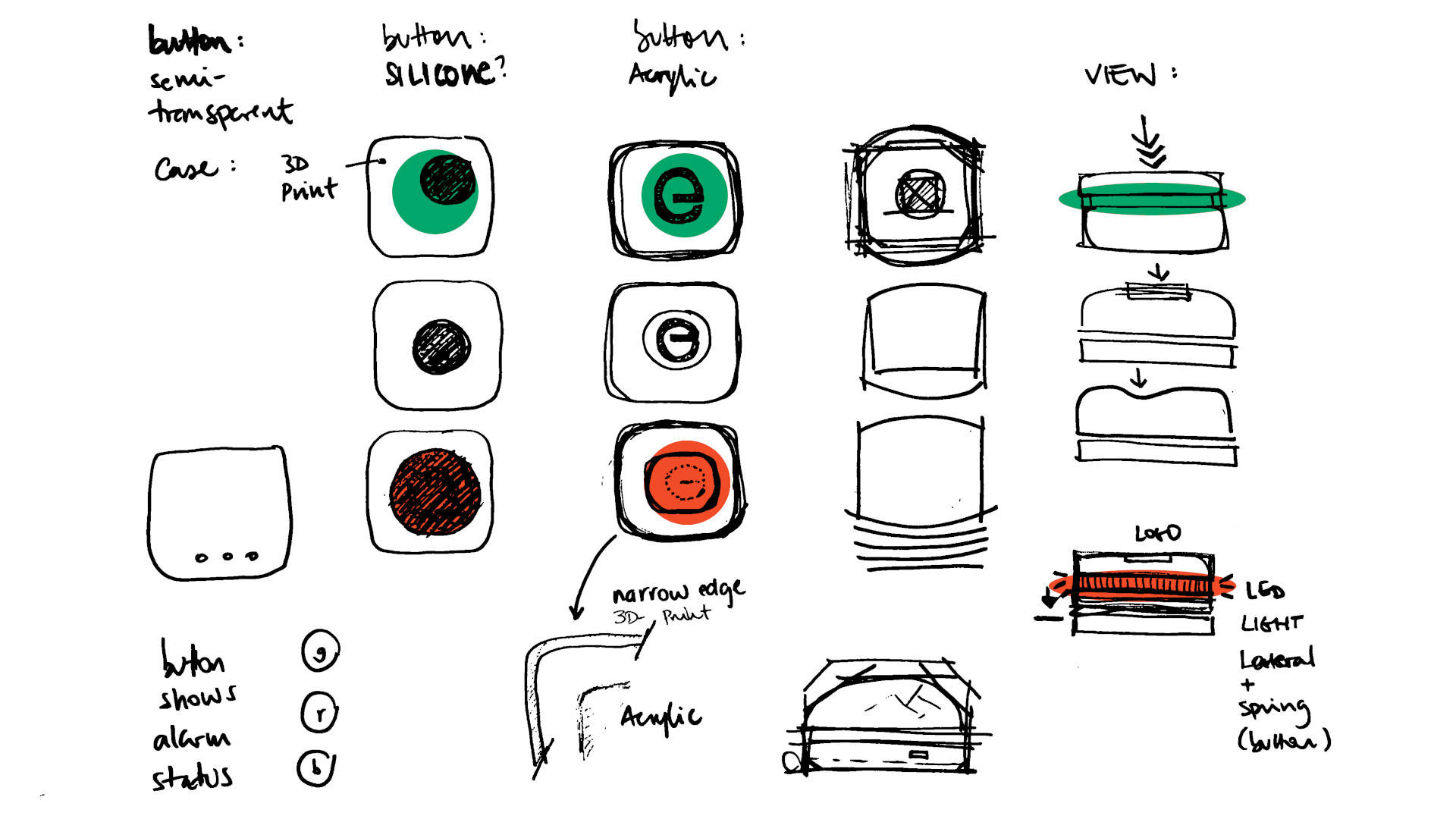
- Enclosure: main body and lid
- Semi-transparent insert elements in the case
- PCB design
- Labeling and Packaging
- Code
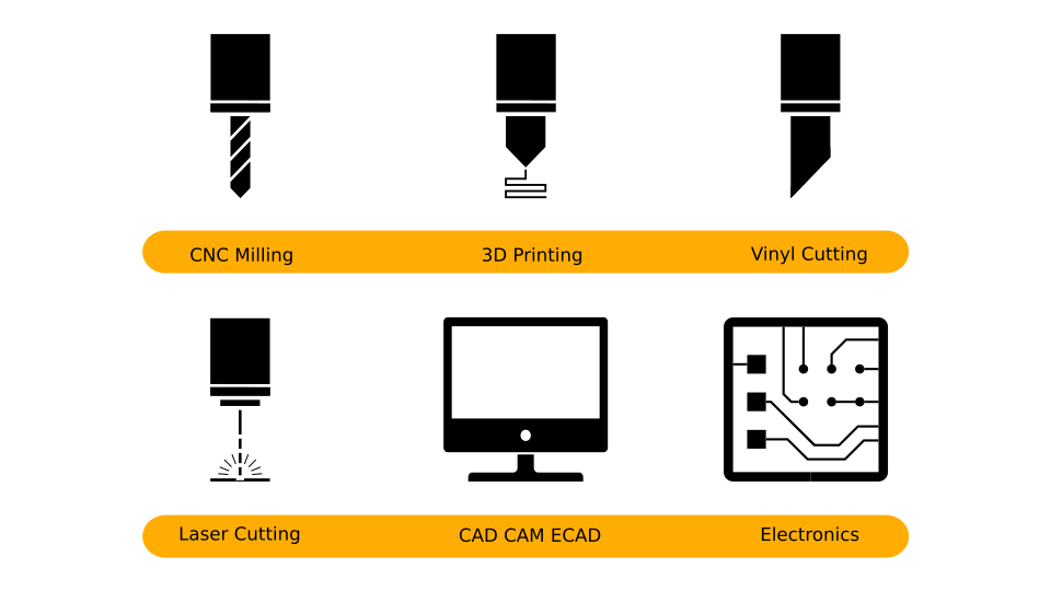
What processes will be used?
- 3D modeling CAD for the case, lid and button
- 3D printing for the case, lid and button
- Laser cutting for some inst elements
- Electronics design software (Eagle)
- CNC milling (fabmodules) for the PCB
- SMD Soldering
- Vacuum forming
- Vinyl cutting for labeling
What questions need to be answered?
- Connection between transmitter and receiver and coding
- Module connecting to the internet
- Electronic design and developing the board
- Interface setup and sending the e-mail coding
- Case test printings and fittings
How will it be evaluated?
The system is basically tested in three parts:
First, the communication between transmitter and receiver is tested.
Then the connection from the receiver to the interface.
Finally, the sending of the e-mail to the specified recipient is tested.
When the entire systems is working, it is presented to different users. Adjustments are made according to user feedback.
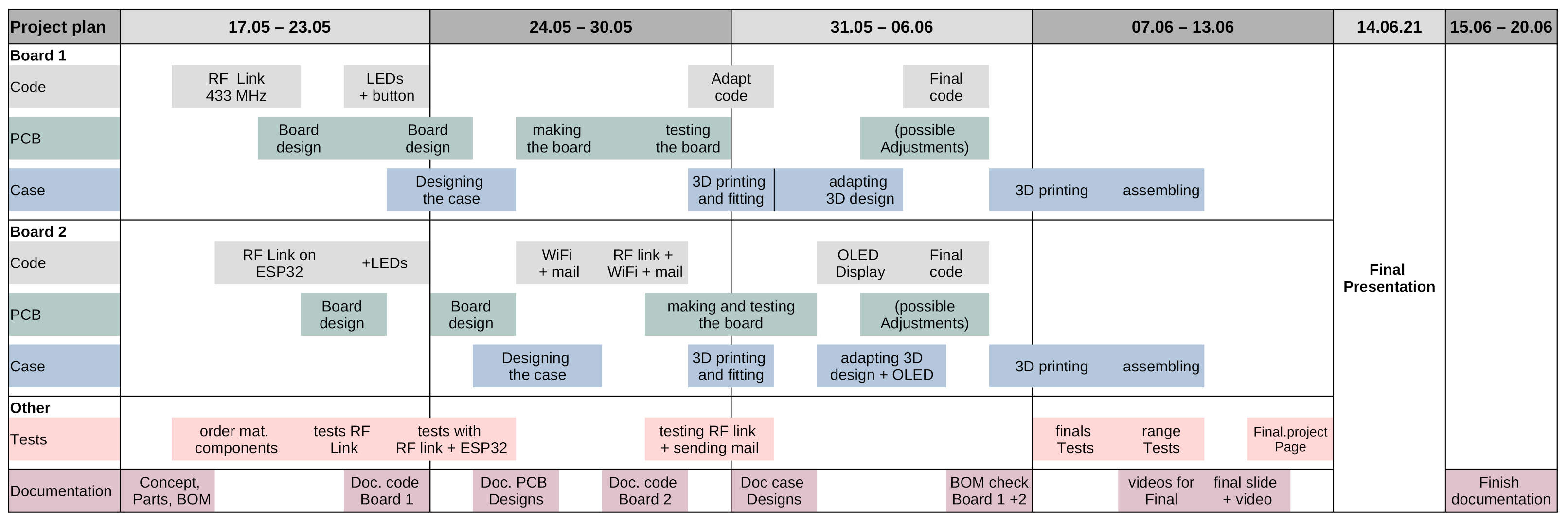
Project plan
Here is the project plan to have the overview of the final project. Since I have two boards, I have the topics code, PCB and enclosure for each board. In addition, the tests with both boards and the documentation run in parallel. The documentation will be completed after the presentation of the final project.