Task:
INDIVIDUAL assignment
- design and build a wired and/or wireless network connecting at least two processors
GROUP assignment
- send a message between two projects
Send a message between two projects
Design and build a wired and/or wireless network connecting at least two processors
The topic of the week “Network and Communications” is new for me, so I start with the basics:
Asynchronous and Synchronous Serial Interfaces
There are two groups of serial interfaces: asynchronous and synchronous. A synchronous serial bus (SPI, I²C) pairs its data line(s) with an external clock signal. For this to happen at least one extra wire is needed between the devices. Asynchronous serial interfaces transfer data without an external clock signal.
Synchronous Serial interfaces
I²C Bus
The Inter-integrated Circuit (I²C) is a synchronous serial protocol, that connects low-speed devices such as microcontrollers, EEPROMs, A/D and D/A converters, I/O interfaces and other similar peripherals devices in embedded systems using two wires.
I²C is very popular because it is easy to use. With I²C you can connect multiple slaves to a single master or multiple masters to a single slave. This is useful for example when two microcontrollers send data to a single memory card.
Interface - I²C uses two wires:
SDA (Serial Data) – the line for sending and receiving data between master and slave.
SCL (Serial Clock) – the line for the clock signal controlled by the master.
Each device can be a transmitter, a receiver or both. Some devices are masters – they generate bus clock and initiate communication on the bus, other devices are slaves.
I²C Addresses
Each I²C slave device has a 7-bit address, which must be unique on the bus. There are also devices, which have a 10-bit address.
Master devices (usually microcontrollers) do not need an address, because no other (slave) device sends commands to the master.
I²C Protocol
Messages consist of two types of frames: a 7-bits address frame and one or more 8-bits data frames. The address frame is sent from the master to the slave master want to talk to. The data frames are sent by the master or slave.
In normal state, both lines (SCL and SDA) are high. Communication is initiated by the master device, which creates the START condition (S) and leaves SCL high and pulls SDA low. After the Start condition, the bus is considered busy. The start condition is followed by the address of the slave device.
Once all data bytes are read or written the master device generates STOP condition (P). To generate the Stop condition the master pulls the SCL line up and stays high before SDA changes its condition 0→1 (low to high).
Signals
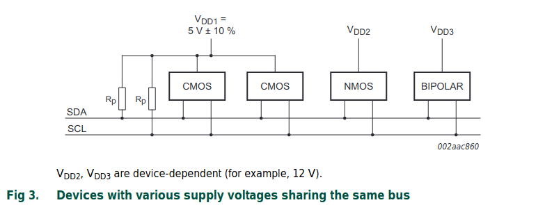
The two signals (SCL and SDA) are bidirectional. They are connected to a positive power supply voltage (+Vdd) via pulled up resistors . This means that both lines are high when the bus is free. If the signal line is busy, it is set to low by the device using it. Here are some links I find very useful to understand the basics of I²C:
HARDWARE
New boards #1 and #2
For this assignment I have to design and build new boards. As a basis for the new boards I read the documentation to build a Satshakit, which is an Arduino IDE/libraries compatible board.
BOARD #1:
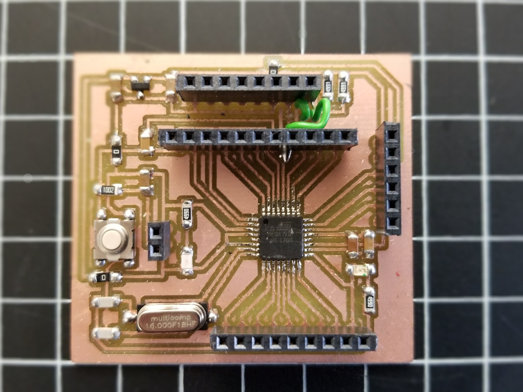
I download the standard-files for the CNC milling and start a new design in Eagle. The grid on the board design is 2,54×2,54 mm.
BOARD #2:
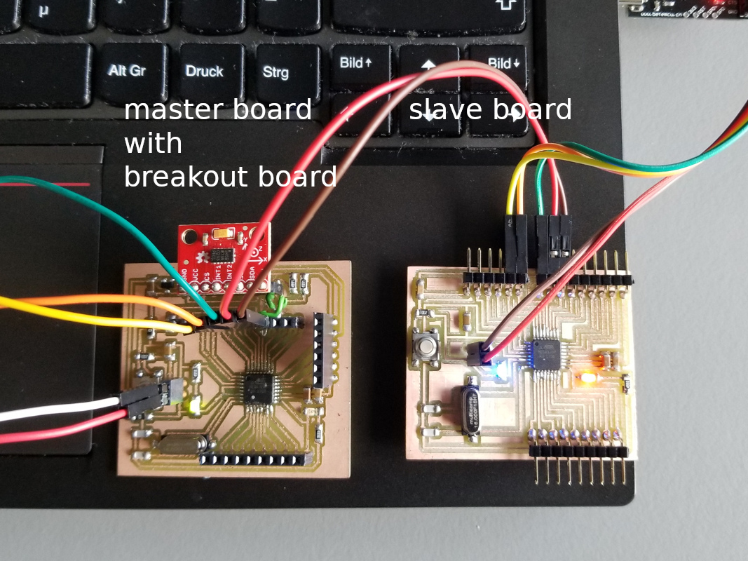
The second board is like the first one, but new connections have been added. The pins of the SparkFun Breakout board ADXL345 should fit into board #2. The new pins/connections are:
- for additional SDA and SCL connections and the pull-up resistors (4.7 kOhm)
- new GND and 3.3V power supply pins for the breakout-board, which only tolerates 3.3V power supply. To change the voltage from 5V to 3.3 Volt I add two 10uF capacitors and a voltage regulator.
After finishing the schematic and board design, I follow the steps I have explained in the weeks ‘Electronics Production’ and ‘Electronics Design’:
export settings in Eagle, png Files for the Roland Mill file and using the fabmodules.org site.
BOARD #3: SparkFun breakout board ADXL345
The ADXL345 is an accelerometer sensor that measures the physical acceleration (magnitude and direction) experienced by an object as a vector quantity.
The ADXL345 is a small, thin, low power, 3-axis MEMS accelerometer with high resolution measurement at up to +-16 g. 3-axis means that it can measure acceleration in 3 directions simultaneously. It is accessible through either an SPI (3- or 4-wire) or I²C digital interface. I decide to work with the I²C interface for this assignment.
The ADXL345 accelerometer measures the static acceleration of gravity and dynamic acceleration resulting from motion or shock. It has also special sensing functions such as activity and inactivity sensing detect, single or double taps and free-fall detection.
LINK Accelerometer ADXL345 and Datasheet
For this assignment I use the breakout board ‘SparkFun Triple Axis Accelerometer Breakout – ADXL345’ and read its tutorial on the SparkFun Site. First you have to connect the pins GND, VCC, SDA, SCL to the corresponding pins on the board.
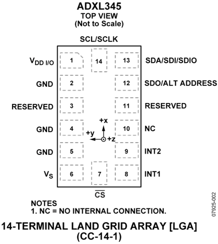
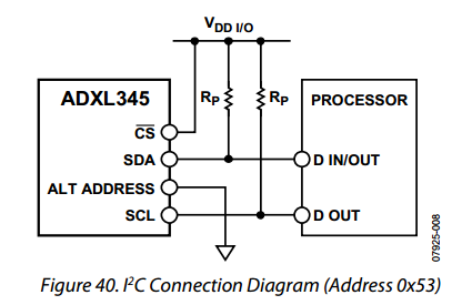
If you are using the sensor as an I²C device, you have to connect the Chip Select (CS) pin to VCC (according to the data sheet) to enable the I²C mode.
The ALT ADDRESS/SDO pin should not be left floating, it must be connected it to GND or VCC.
LINK SparkFun ADXL345 Hookup Guide
You find the Eagle (schematic, board design and the partlists) and RML files in the Download section.
Programming the boards
My goal is to trigger an LED on the slave board using the accelerometer breakout board on the master board.
Board 1 (master) + board 2 (slave): After I have milled and soldered all parts, I follow the ‘Getting Started’-instructions from the “README.md”-file in the Satshakit documentation. With a programmer (Arduino UNO as ISP) I successfully upload the Arduino bootloader to the new boards and then the Arduino sketches.
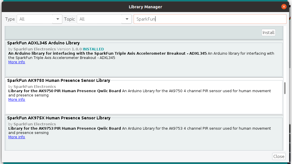
Board 3 (breakoutboard on the master board): I will test the Example SparkFun Code for the breakout board. First you have to include the SparkFun_ADXL345 Arduino Library.
Go to the Arduino IDE >Sketch >Include Library >Manage Libraries. Then search after ADXL345, at the bottom of the list you will find the library to install. After installing the library, you will find the example codes in the Sketchbook.
CODE
Code #1:
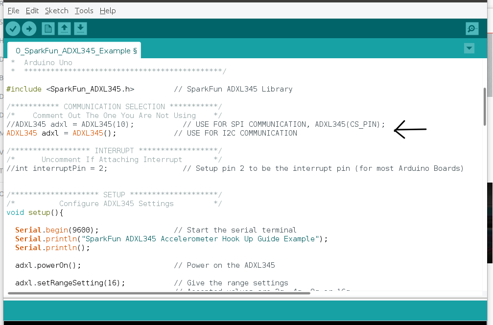
I take the ‘Example Code’ for the master board (with the breakout board) and select the communication mode: I choose I²C and comment out SPI communication. You can find the example codes on the Tutorial page of SparkFun.
In the download section you find the example code with newly added functions (marked with #): the LED blinks and a sound effect is played as soon as the accelerometer detects activity.
Code #2:
Then I will test the master and slave codes from an Instructables tutorial. The original codes can be found in the link below. Note that I had to delete the apostrophe to print the integer:
if (x == '3') → if (x == 3)
Code #3:
Finally I integrated the master code from the Instructables tutorial into the example code for the ADXL345.
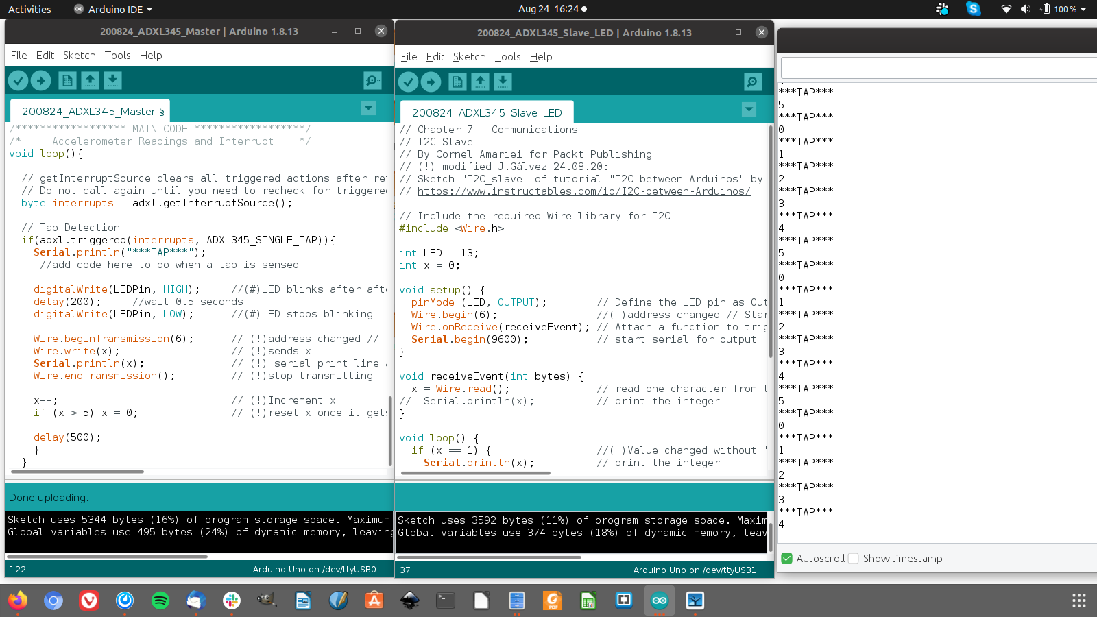
MASTER: when the accelerometer detects any activity with the ADXL345, the LED blinks and the master addresses the slave and sends an integer value to the slave board. At each activity detection, the master board increases this value by 1 until it gets 6.
SLAVE: the slave board has also an embedded LED. The slave reads the message and blinks its LED only when the slave board receives the values 0 or 3. You can change the integer values or add some. Watch my video.
CODE #3: Master
 *  SparkFun_ADXL345_Example
 *  Triple Axis Accelerometer Breakout - ADXL345
 *  Hook Up Guide Example
 *
 *  Utilizing Sparkfun's ADXL345 Library
 *  Bildr ADXL345 source file modified to support
 *  both I2C and  SPI Communication
 *
 *  E.Robert @ SparkFun Electronics
 *  Created: Jul 13, 2016
 *  Updated: Sep 06, 2016
 *
 *  Development Environment Specifics:
 *  Arduino 1.6.11
 *
 *  Hardware Specifications:
 *  SparkFun ADXL345
 *  Arduino Uno
 *
 *  (#) modified J. Gálvez 08.04.19:
 *  Switches LED on or off when the accelerometer detects activity.
 *  LED connected to digital pin 13
 *  (!) modified J.Gálvez 24.08.20:
 *  ISR part reduced, SINGLE TAP left
 *  Sketch "I2C Master" of tutorial "I2C between Arduinos" by instructables adapted and inserted, Authors: By Cornel Amariei for Packt Publishing
 *  https://www.instructables.com/id/I2C-between-Arduinos/
 *
 *  *********************************************/

#include "SparkFun_ADXL345.h"   // SparkFun ADXL345 Library
#include "Wire.h"               // ! Include the required Wire library for I2C

const int LEDPin=13;            // (#) LED connected to digital pin 13
int x = 0;                      // !

/*********** COMMUNICATION SELECTION ***********/
/*    Comment Out The One You Are Not Using    */
//ADXL345 adxl = ADXL345(10);           // USE FOR SPI COMMUNICATION, ADXL345(CS_PIN);
ADXL345 adxl = ADXL345();             // USE FOR I2C COMMUNICATION

/****************** INTERRUPT ******************/
/*      Uncomment If Attaching Interrupt       */
//int interruptPin = 2;                 // Setup pin 2 to be the interrupt pin (for most Arduino Boards)

/******************** SETUP ********************/
/*          Configure ADXL345 Settings         */
void setup(){

  Wire.begin();                       // ! Start the I2C Bus as Master
  Serial.begin(9600);                 // Start the serial terminal
  Serial.println("SparkFun ADXL345 Accelerometer Hook Up Guide Example");
  Serial.println();

  adxl.powerOn();                     // Power on the ADXL345

  adxl.setRangeSetting(16);           // Give the range settings
                                      // Accepted values are 2g, 4g, 8g or 16g
                                      // Higher Values = Wider Measurement Range
                                      // Lower Values = Greater Sensitivity

  adxl.setSpiBit(1);                  // Configure the device to be in 4 wire SPI mode when set to '0' or 3 wire SPI mode when set to 1
                                      // Default: Set to 1
                                      // SPI pins on the ATMega328: 11, 12 and 13 as reference in SPI Library

  adxl.setActivityXYZ(1, 1, 1);       // Set to activate movement detection in the axes "adxl.setActivityXYZ(X, Y, Z);" (1 == ON, 0 == OFF)
  adxl.setActivityThreshold(50);      // 62.5mg per increment   // Set activity   // Inactivity thresholds (0-255)

  adxl.setInactivityXYZ(1, 1, 1);     // Set to detect inactivity in all the axes "adxl.setInactivityXYZ(X, Y, Z);" (1 == ON, 0 == OFF)
  adxl.setInactivityThreshold(50);    // 62.5mg per increment   // Set inactivity // Inactivity thresholds (0-255)
  adxl.setTimeInactivity(10);         // How many seconds of no activity is inactive?

  adxl.setTapDetectionOnXYZ(0, 0, 1); // Detect taps in the directions turned ON "adxl.setTapDetectionOnX(X, Y, Z);" (1 == ON, 0 == OFF)

  // Set values for what is considered a TAP and what is a DOUBLE TAP (0-255)
  adxl.setTapThreshold(50);           // 62.5 mg per increment
  adxl.setTapDuration(15);            // 625 μs per increment
  adxl.setDoubleTapLatency(80);       // 1.25 ms per increment
  adxl.setDoubleTapWindow(200);       // 1.25 ms per increment

  // Set values for what is considered FREE FALL (0-255)
  adxl.setFreeFallThreshold(5);       // (5 - 9) recommended - 62.5mg per increment
  adxl.setFreeFallDuration(20);       // (20 - 70) recommended - 5ms per increment

  // Setting all interupts to take place on INT1 pin
  //adxl.setImportantInterruptMapping(1, 1, 1, 1, 1);     // Sets "adxl.setEveryInterruptMapping(single tap, double tap, free fall, activity, inactivity);"
                                                        // Accepts only 1 or 2 values for pins INT1 and INT2. This chooses the pin on the ADXL345 to use for Interrupts.
                                                        // This library may have a problem using INT2 pin. Default to INT1 pin.

  // Turn on Interrupts for each mode (1 == ON, 0 == OFF)
  adxl.InactivityINT(1);
  adxl.ActivityINT(1);
  adxl.FreeFallINT(1);
  adxl.doubleTapINT(1);
  adxl.singleTapINT(1);

  //attachInterrupt(digitalPinToInterrupt(interruptPin), ADXL_ISR, RISING);   // Attach Interrupt

  pinMode(LEDPin, OUTPUT);            //(#)

}

/****************** MAIN CODE ******************/
/*     Accelerometer Readings and Interrupt    */
void loop(){

  // getInterruptSource clears all triggered actions after returning value
  // Do not call again until you need to recheck for triggered actions
  byte interrupts = adxl.getInterruptSource();

  // Tap Detection
  if(adxl.triggered(interrupts, ADXL345_SINGLE_TAP)){
    Serial.println("***TAP***");
     //add code here to do when a tap is sensed

    digitalWrite(LEDPin, HIGH);     //(#)LED blinks after after detecting tap
    delay(200);     //wait 0.5 seconds
    digitalWrite(LEDPin, LOW);      //(#)LED stops blinking

    Wire.beginTransmission(6);      // (!)address changed // transmit to device address #6
    Wire.write(x);                  // (!)sends x
    Serial.println(x);              // (!) serial print line added -> look at serial monitor
    Wire.endTransmission();         // (!)stop transmitting

    x++;                            // (!)Increment x
    if (x > 5) x = 0;               // (!)reset x once it gets 6

    delay(500);
    }
}
CODE #3: Slave
// Chapter 7 - Communications
// I2C Slave
// By Cornel Amariei for Packt Publishing
// (!) modified J.Gálvez 24.08.20:
// Sketch "I2C_slave" of tutorial "I2C between Arduinos" by instructables adapted and inserted, Authors: By Cornel Amariei for Packt Publishing
// https://www.instructables.com/id/I2C-between-Arduinos/

// Include the required Wire library for I2C
#include "Wire.h"

int LED = 13;
int x = 0;

void setup() {
  pinMode (LED, OUTPUT);        // Define the LED pin as Output
  Wire.begin(6);                //(!)address changed // Start the I2C Bus as Slave on address 6
  Wire.onReceive(receiveEvent); // Attach a function to trigger when something is received.
  Serial.begin(9600);           // start serial for output
}

void receiveEvent(int bytes) {
  x = Wire.read();              // read one character from the I2C
//  Serial.println(x);          // print the integer
}

void loop() {
  if (x == 1) {                 //(!)Value changed without '' // If value received is 0 blink LED for 200 ms
    Serial.println(x);          // print the integer
    digitalWrite(LED, HIGH);
    delay(200);
    digitalWrite(LED, LOW);
    delay(200);
  }
  if (x == 3) {                 //(!)Value changed without '' //If value received is 3 blink LED for 400 ms
    Serial.println(x);          // print the integer
    digitalWrite(LED, HIGH);
    delay(400);
    digitalWrite(LED, LOW);
    delay(400);
  }
}
Code #3: Accelerometer on master board, LED on slave board
Download
| Board 1: Eagle, image (png), CNC (rml) files and partlist(zip) | Download |
| Board 2: Eagle, image (png), CNC (rml) files and partlist(zip) | Download |
| Arduino Sketches Code 1 and Code 2 (zip) | Download |
| Arduino Sketches Code 3 (zip) | Download |

 I²C-bus
 I²C address
 Data transfer
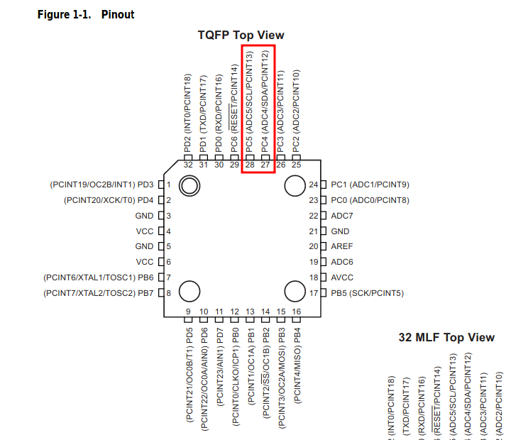 ATmega328P Pin Configuration
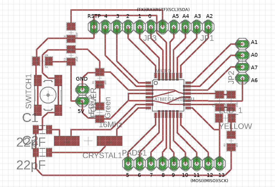 Board 1
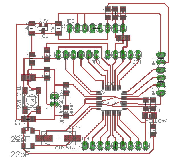 Board 2
 ADXL345 Arduino Library
 Master Board
 Boards
 Code #1: I²C Mode
 Code #3: Serial Monitor