Task:
INDIVIDUAL assignment
- add an output device to a microcontroller board you've designed,
and program it to do something
GROUP assignment:
- measure the power consumption of your output device
Measure the power consumption of your output device
ADDING AN OUTPUT DEVICE TO A BOARD
For this week, I am making two boards:
Board #1:
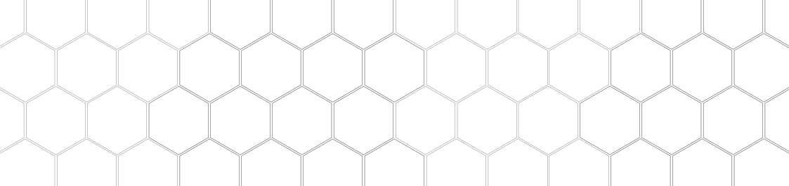
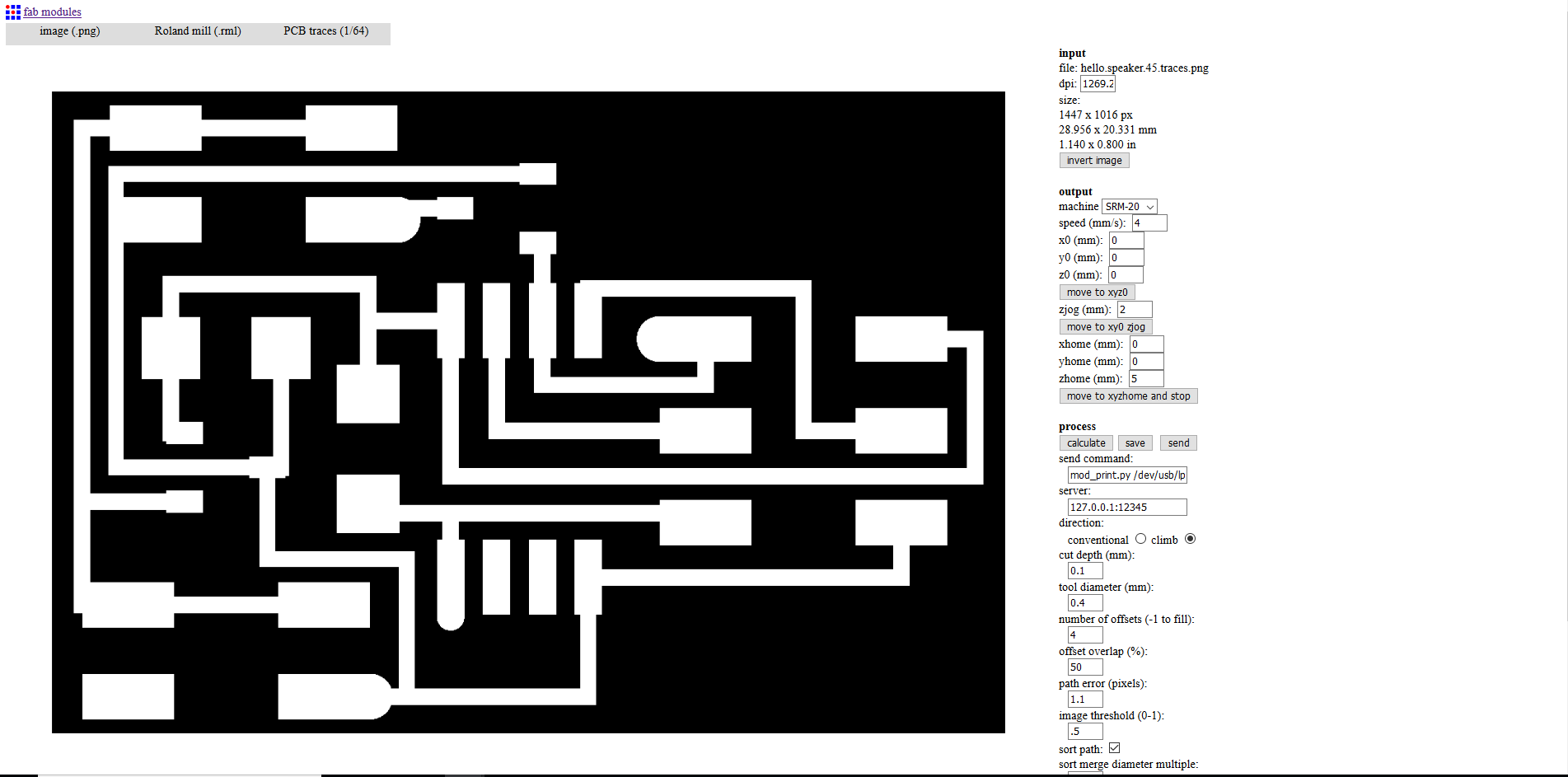
First is the template for the speaker from the lecture.
I take the PNG files, load them into fabmodules and calculate the toolpath to mill the PCB with the Roland machine.
To connect the micro speaker I use a 6-way connector and a ribbon cable. I cut off the wires I don’t need and repeat these steps to connect the board to the 9 volt battery.
Board #2:
The second board is a FabKit bord, I use my instructor Marcel Kellner’s FabKit board as a template, which I trace in Eagle.
Output Devices | FabKit | Marcel Kellner
Note:
I made a mistake in selecting the outline for the FabKit and chose a smaller one. The end-mill cut three traces between the 6-pin header
and the ATmega328p.
I fix the traces with a wire, I hope it works. It is also necessary to remove the 12 pins, flex them with pliers and solder them back on.
PARTLIST FOR THE PCB WITH SPEAKER
| IC1 | Attiny45 |
| T1 | N Mosfet |
| JI_ISP | 6 position |
| J2_power | 4 Positions header |
| J3_speaker | 4 Positions header |
| Capacitor 1 | 1uF |
| Resistor 1 | 10kOhms |
| IC2_Regulator | 5Vout |
| Micro Speaker | . |
| Ribbon cable | . |
| 4-way connectors | . |
PARTLIST FOR THE FABKIT BOARD
Go to the download section.
 Board #1
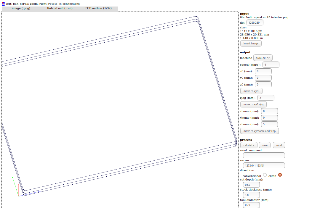 Board #1
 Board #2
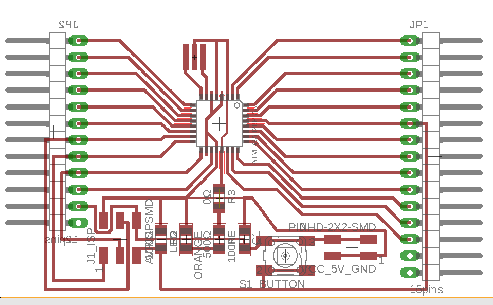 Board #2
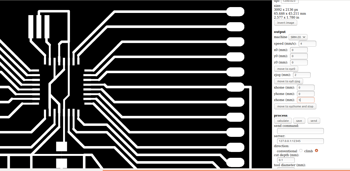 Board #2
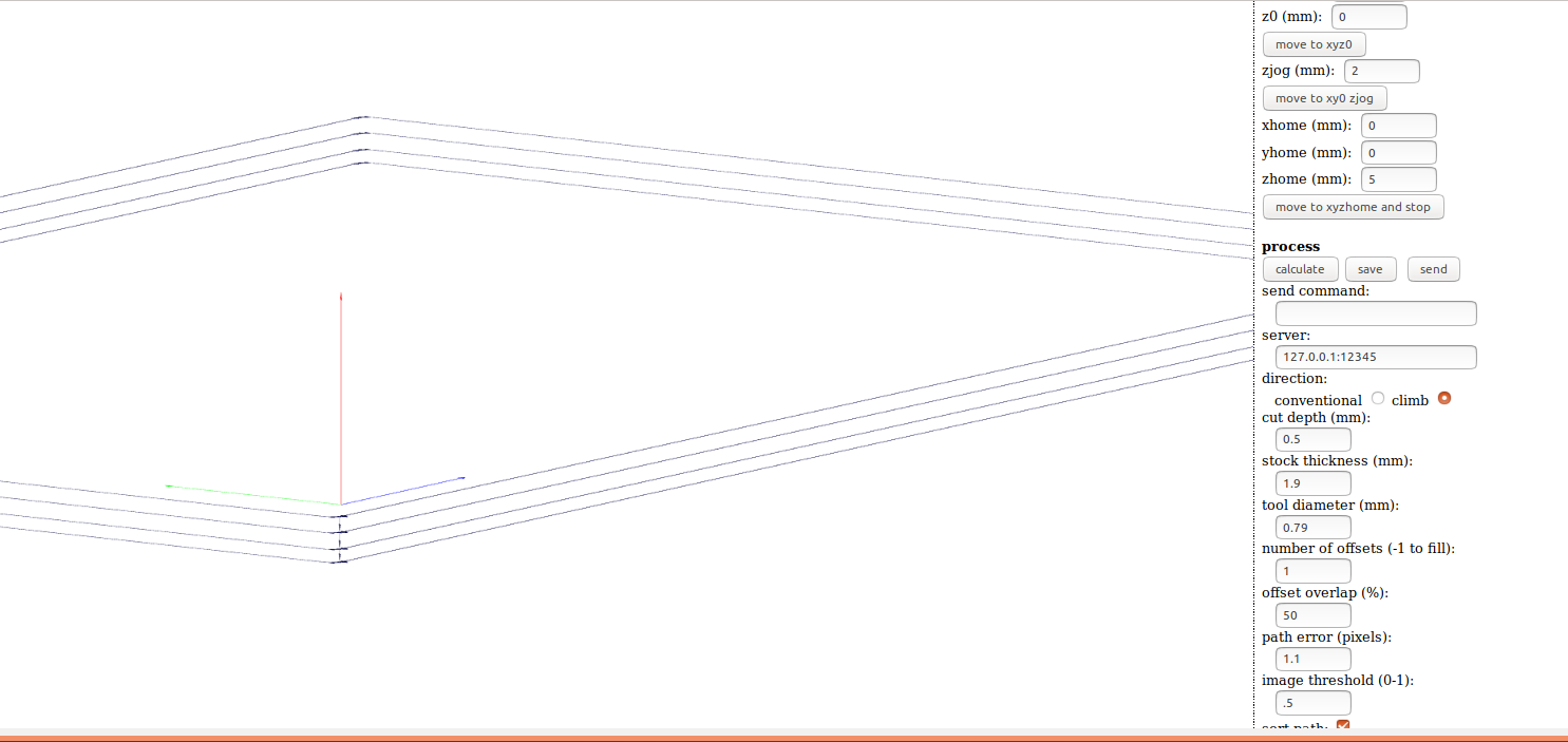 Board #2
PROGRAMMING THE OUTPUT DEVICE TO DO SOMETHING
Ubuntu | Make File
After I connect the board #1 to the ATMEL ICE and the battery, I download the Make and C files of the lecture:
In ubuntu terminal
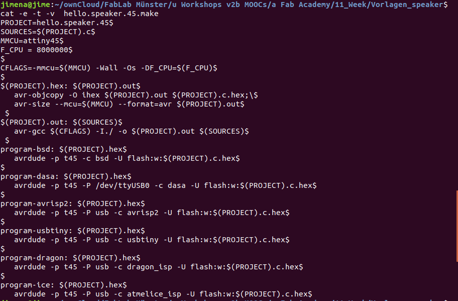
→ $ make -f hello.speaker.45.make
Ubuntu shows an error with the Make file:
→ hello.speaker.45.make:9: *** missing separator. Stop.
- I check this error on the internet and find this command to check the text in the Make file:
→ $ cat -e -t -v makefile_name
There is a problem with the space before the action part, instead of one tab there are 4 spaces. I change the Make file with a text editor. I check the Make file again with the following command.
→ $ cat -e -t -v makefile_name
The tabs before the action part are correct now.
I run the make file again and the HEX and OUT file are generated.
→ $ make -f hello.speaker.45.make
After that I enter this command in the terminal, the HEX-file is updated:
→ $ sudo make -f hello.speaker.45.make program-ice
And the music starts playing!
 Make file
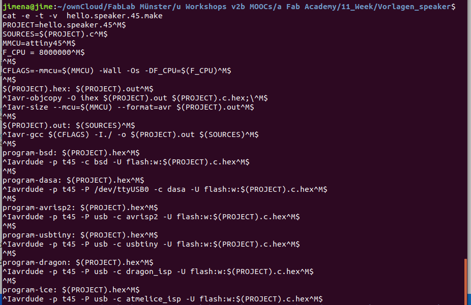 Make file
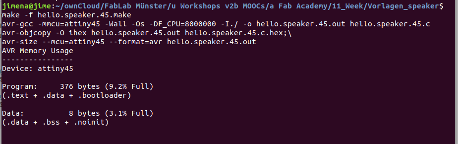 Make file
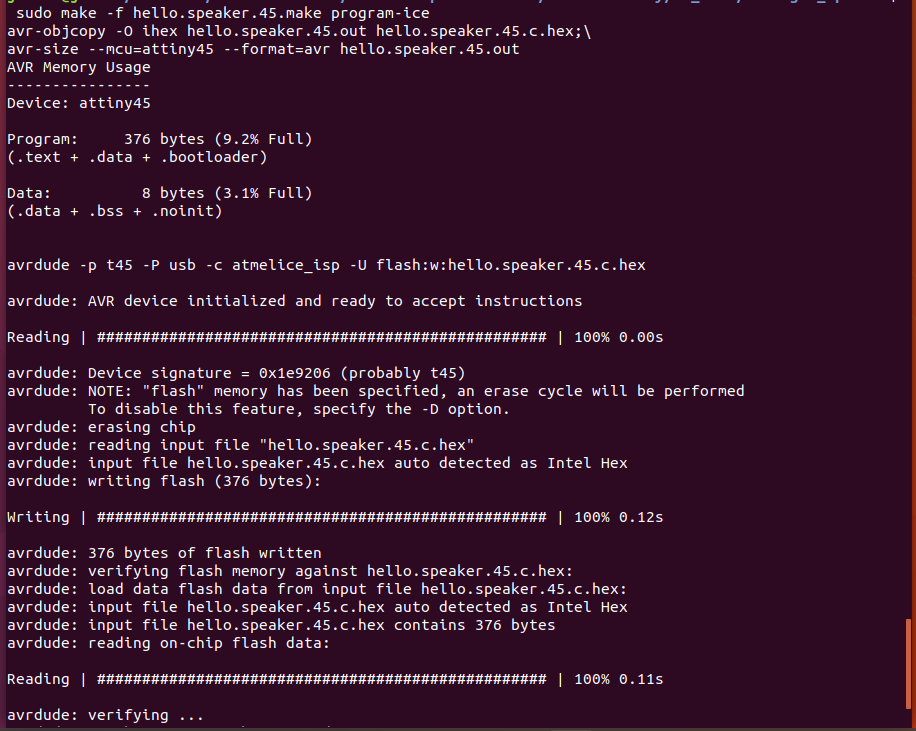 Make file
UBUNTU | ARDUINO IDE
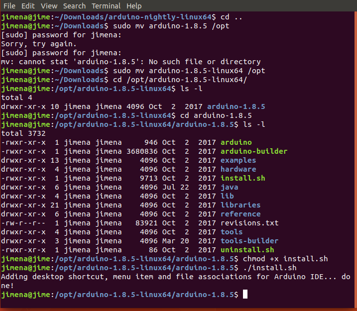
I am researching how to use the Atmel ICE with Arduino. First I search for Arduino updates. In the version 1.8.5 the Atmel ICE is added as programmer.
I follow the instructions in this tutorial to install the update:
Upgrade the latest Arduino IDE on Linux
The next step is to add the microcontroller ATmega328p (board #2) to the Boards Manager in the Arduino IDE.Check this tutorial:
Carlosefr: Program ATmega microcontrollers in the Arduino IDE
and go to 'Install' to copy the URL.
- Open the Arduino IDE, go to the 'File' menu and then to 'Preferences':
- In 'Additional Boards Manager URLs': copy the URL from the github tutorial.
- Go to Tools > Board > Boards Manager, and search for Barebones ATmega Chips, click on install.
- Now you will see the ATmega micro-controllers in the boards list.
 Arduino Update
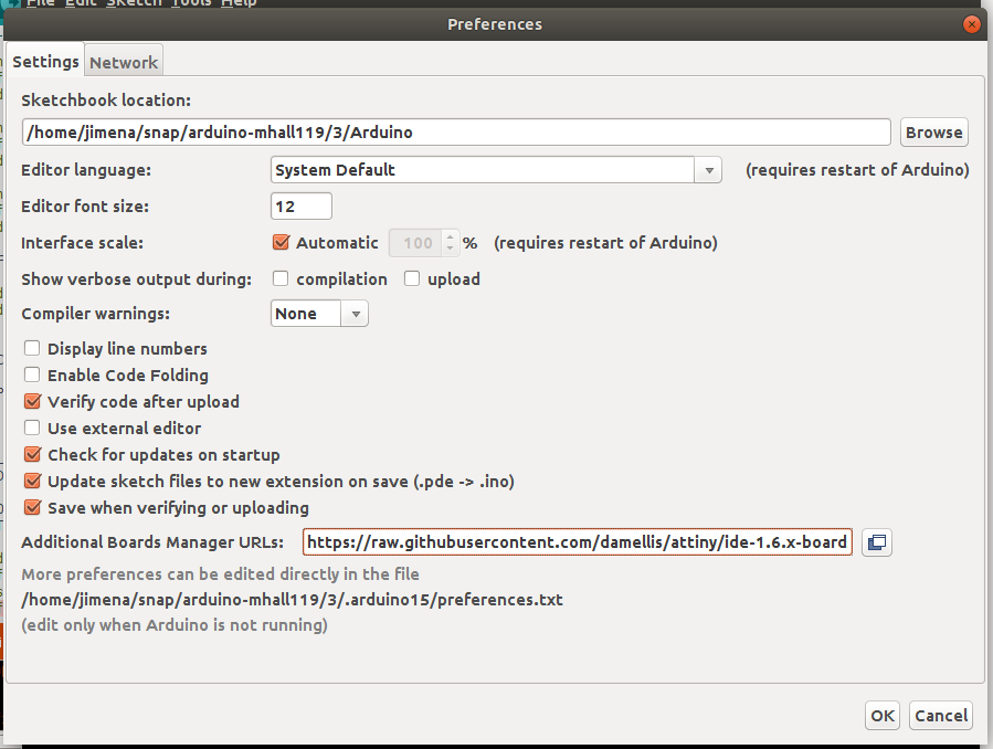 Arduino Preferences
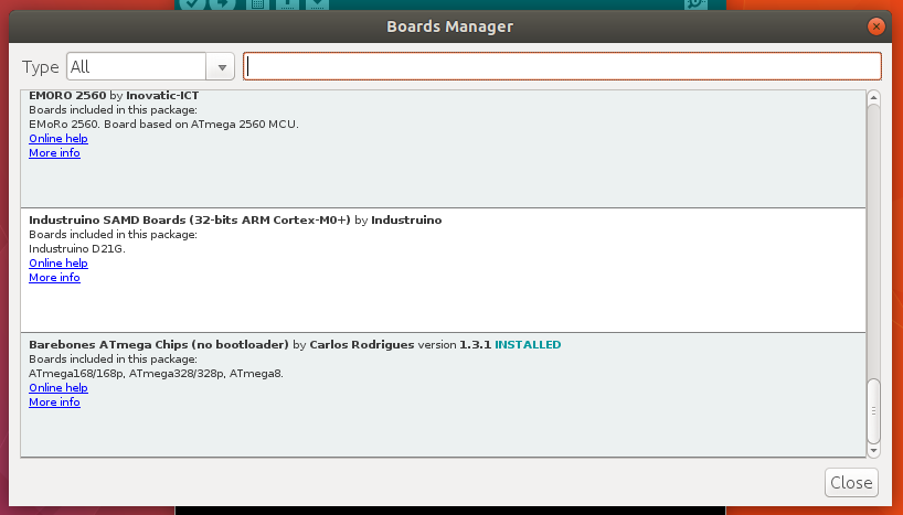 Arduino Boards Manager
Download
| Baord with speaker: RML files (zip) | Download |
| FABKIT: Eagle: Schematic, Board Layout and Partlist (zip) | Download |
| FABKIT: Image and RML files (zip) | Download |
UPDATE (global evaluation)
During the global correction I was informed that I have to create my own board design. Therefore I start with my own design. I still want a speaker as output device and add an OLED display and 8 switches. The OLED display shows which note is played.
BASICS
N-channel mosfet
I need more current, so I need a transistor on the board, because the output device needs more current than the pin of the microcontroller can provide. To sound louder the current through the speaker has to be increased.
On my board I have an N-mosfet connected to gate, source and gain.
Gate is connected to the pin of the microcontrollers.
Drain is connected to the LOAD. LOAD is the electrical device in an electrical circuit that consumes electrical energy and has an impedance.
Source goes to ground.
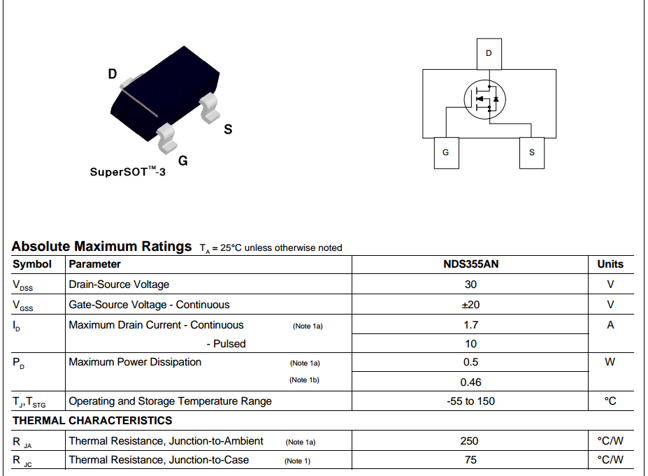
The N-Mosfet I use can handle a drain-source voltage of up to 30V and a maximum drain current of 1.7A.
Impedance
Most speaker have impedance of 4 Ohms till 16 Ohms. The degree in which the loudspeaker impedes the current is aptly called impedance and is expressed in ohm. More in this link: Understanding Speaker Impedance
 N-channel transistor
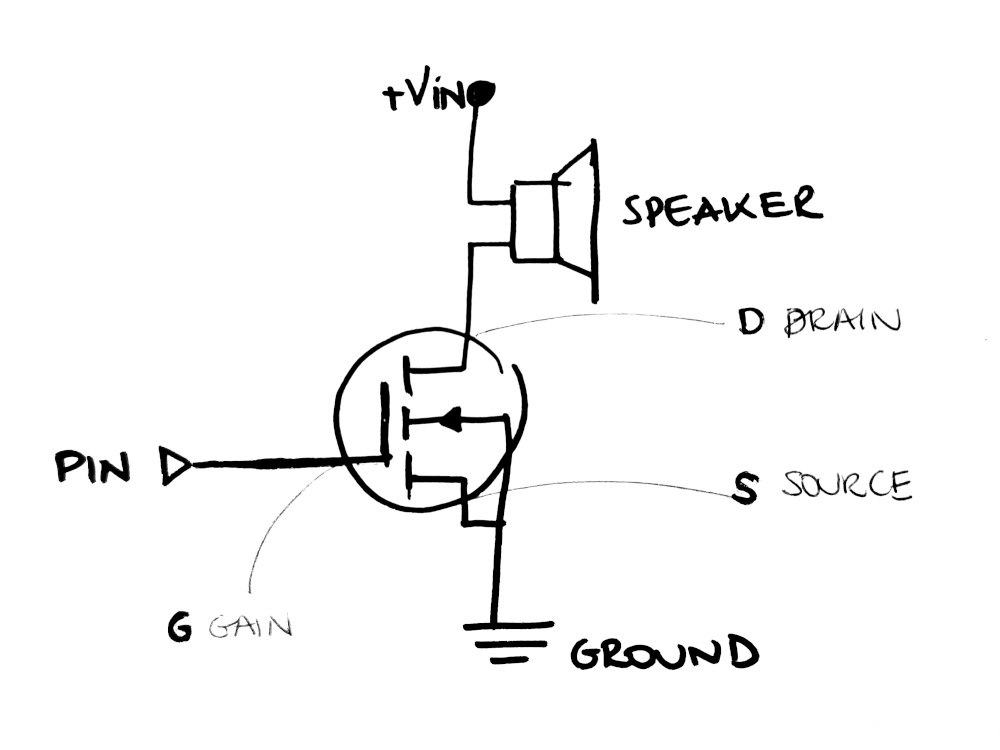 N-channel transistor + speaker
Speaker
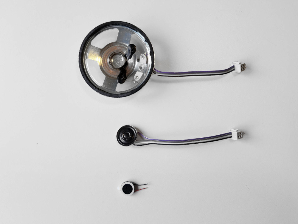
I will test speakers with different sizes. All are 8 ohm (impedance) speakers.
I first try with a small speaker from the manufacturer Kingstate (diameter 20 mm, 8 ohms), which costs 2.20€ (in the middle of the photo).
Then I test the smallest speaker from the manufacturer Multicomp Pro (diameter 13 mm), which costs 1,85€.
At the end I test the largest speaker from the manufacturer Pro Signal (diameter 66mm), which costs about 10€
At the end I test the largest speaker from the manufacturer Pro Signal (diameter 66mm), which costs about 10€
CONCLUSION:
The smaller speakers sound “noisy” in the lower tones. The quality of the biggest speaker is much better without vibration in the sound.
You can hear the differences in volume on the video at the bottom of this page. All speakers were tested with the same voltage.
 8 Ohm speakers
OLED display
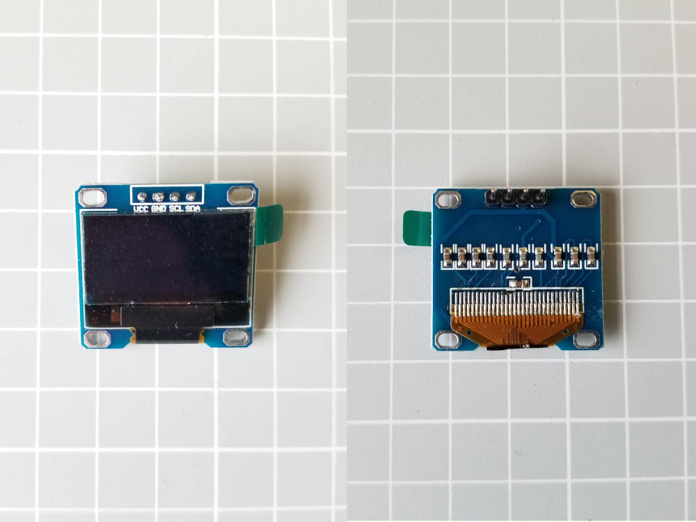
OLED displays are organic light-emitting diode. You can talk to each single pixel.
For more complex graphics I found this tutorial very interesting (Adafruit library) but I used this other tutorial for simple text messages, like the music notes I want to display when I press the switches.
The OLEd display communicates with a single chip OLED driver controller: SS1306.
It communicates in several ways, for example I2C and SPI.
Most of these OLED displays have a charge pump circuit. It can increase or decrease the voltage with the help of capacitors. So it is possible to connect the display directly to a 5V microcontroller pin.
The display I'm using has a black background and blue text (monochrome), its size is 128x64 pixels (128 columns x 64 rows).
 OLED display 128x64
BOARD DESIGNS
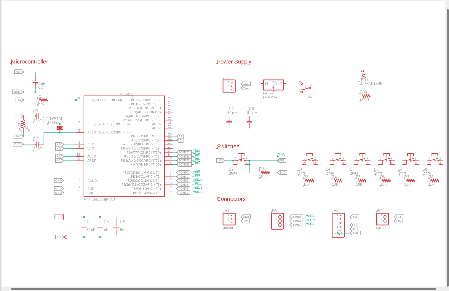
I have designed two boards, The first has a microcontroller ATmega328 on it. The second board is a breakout board, which would be faster to produce, because of the still reduced opening hours in the fab lab.
The board is powered by a 9V battery or console. For this reason I add a voltage regulator with an output voltage of 5V. The operating voltage of the Atmega328 is up to a maximum of 5.5V. According to the datasheet two capacitors with a value of 0.1 uF are needed.
If you want to know how to connect the pins of the microcontroller to the input/output devices in the schematic, you can find more about the pinout of the ATmega328p here.The display is controlled via the I²C bus.
 Starting schematic
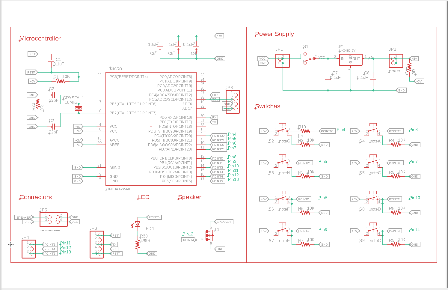 Schematic with microcontroller
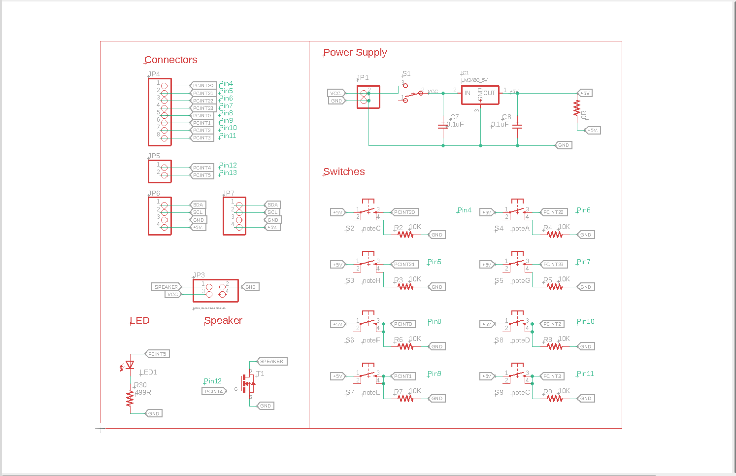 Schematic without microcontroller
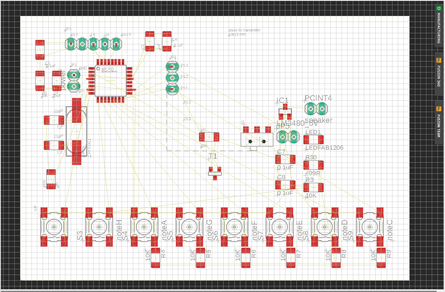 Starting board deign
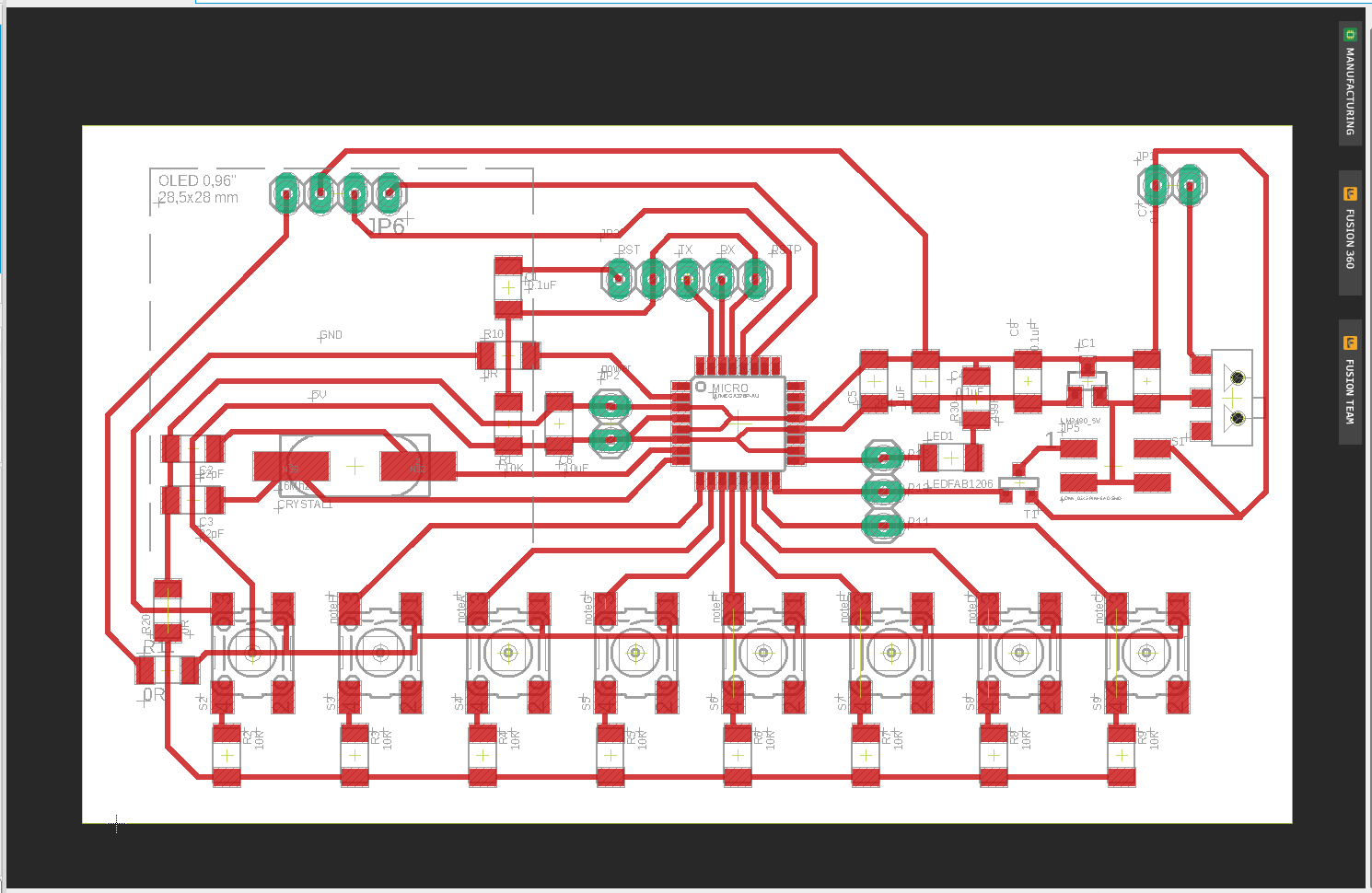 Board design with microcontroller
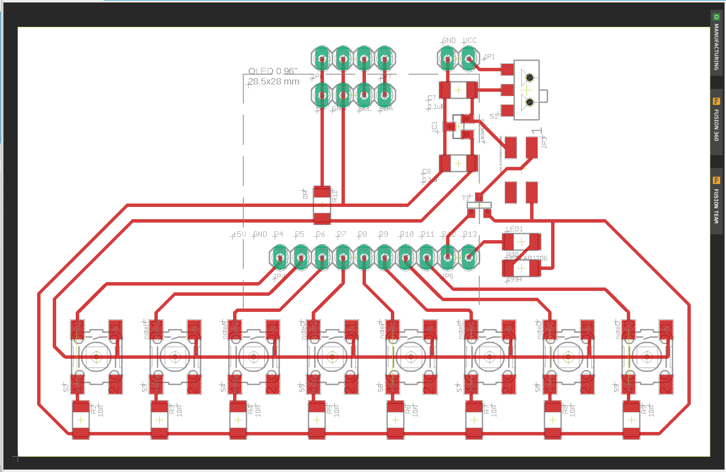 Board design without microcontroller
There are 8 pins for 8 buttons (8 music notes, pins 4 -11), one pin for the N-mosfet, one pin for the LED and 4 pins for the OLED display. The speaker is connected to VCC and the Drain Pin of the N-Mosfet.
To know which notes can be played, there is the Pitches library. More about this in the code part.
| Microcontroller pin | Arduino IDE pin | Component |
|---|---|---|
| PCINT5 | Pin 13 | LED |
| PCINT4 | Pin 12 | N-Mosfet, Gain |
| PCINT3 | Pin 4 | Switch, note C4 |
| PCINT2 | Pin 5 | Switch, note D4 |
| PCINT1 | Pin 6 | Switch, note E4 |
| PCINT0 | Pin 7 | Switch, note F4 |
| PCINT23 | Pin 8 | Switch, note G4 |
| PCINT22 | Pin 9 | Switch, note A4 |
| PCINT21 | Pin 10 | Switch, note H4 |
| PCINT20 | Pin 11 | Switch, note C5 |
| PCINT13 | Pin SCL | Display |
| PCINT12 | Pin SDA | Display |
MAKING the board
The board could not be milled completely because the tip of the milling tool broke. Two paths were not completely milled. For time reasons I decided not to mill a new board, but to separate the remaining paths with a knife. This worked quite well and I could assemble / solder the board.
I soldered the pins for the buttons and the display not on the board but upside down, so that the cables do not disturb later. Only the connectors for the display and the power supply are above.
The speaker is connected to the board with a connector (2x2 pins). I made a sketch for this (right).
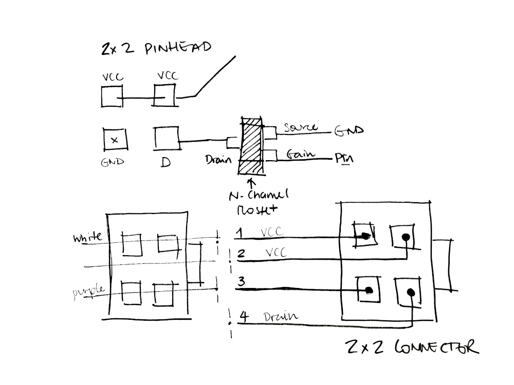 Connector for speaker
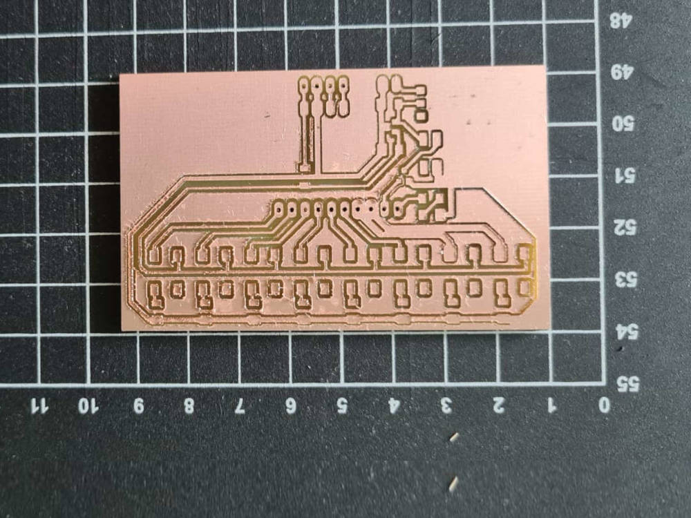 CNC milling the breakout board
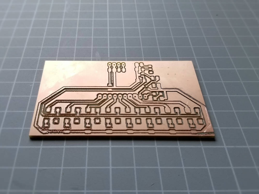 Schematic with microcontroller
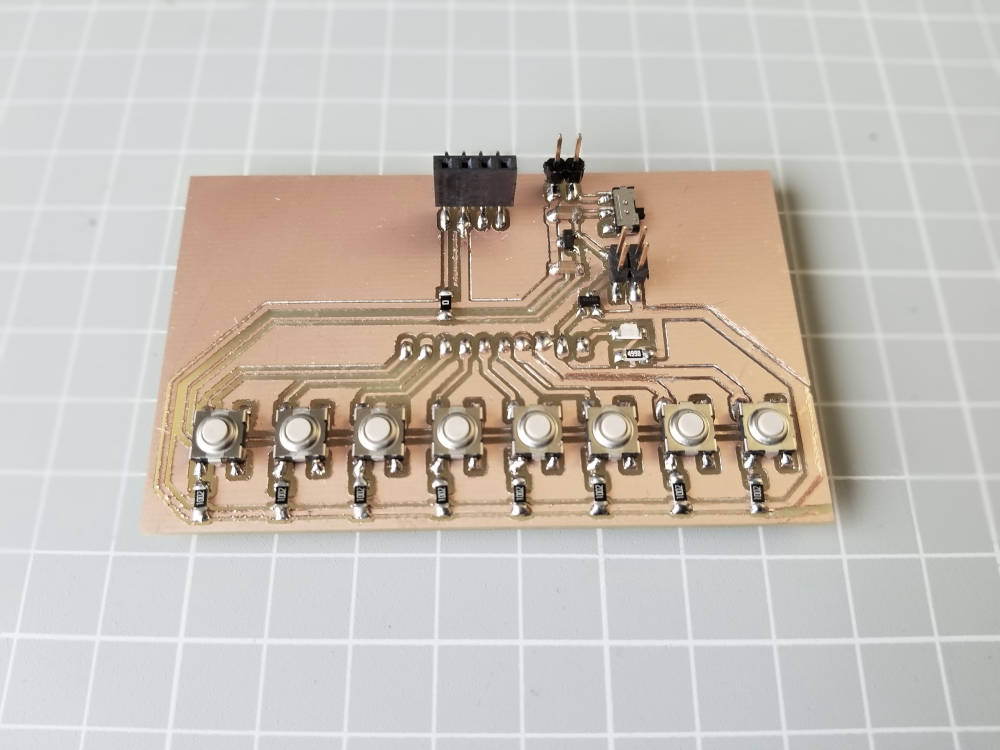 Schematic without microcontroller
CODE
I'll start by reading this page and how the tone() function works.
Adding the PITCHES.H library
The library contains all pitch values for typical notes. It generates a square wave of the specified frequency (audible range) on a pin and was created by Brett Hagman.
First, you need to create a new tab to include the library in your sketch. Name the new tab pitches.h and copy and paste the code for the library. You find the code for the library here.
The first code I adapted plays a part from a children's song.
int melody_test[] = {} Here you insert all the notes that are to be played
int melody_test[] = {} Here you specify the duration of each note
void setup() {} In the iteration each note is played with the corresponding length
void loop() {} The melody is played only once in the setup part.
With the second code I adapted, you can play the buttons
like a small keyboard and read the note on the display at the same time.
At the beginning the constants for the notes and the display are defined, like which pin plays which note. The necessary libraries are also included.
void setup() {} The communication protocol of the display and the font are defined.
The pin modes are also defined.
void loop() {} This part plays the tone/switch you press and the display shows it.
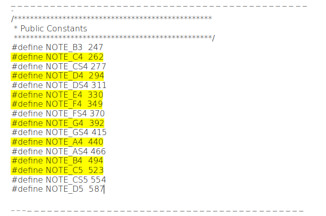 Extract from the Pitches library for music notes
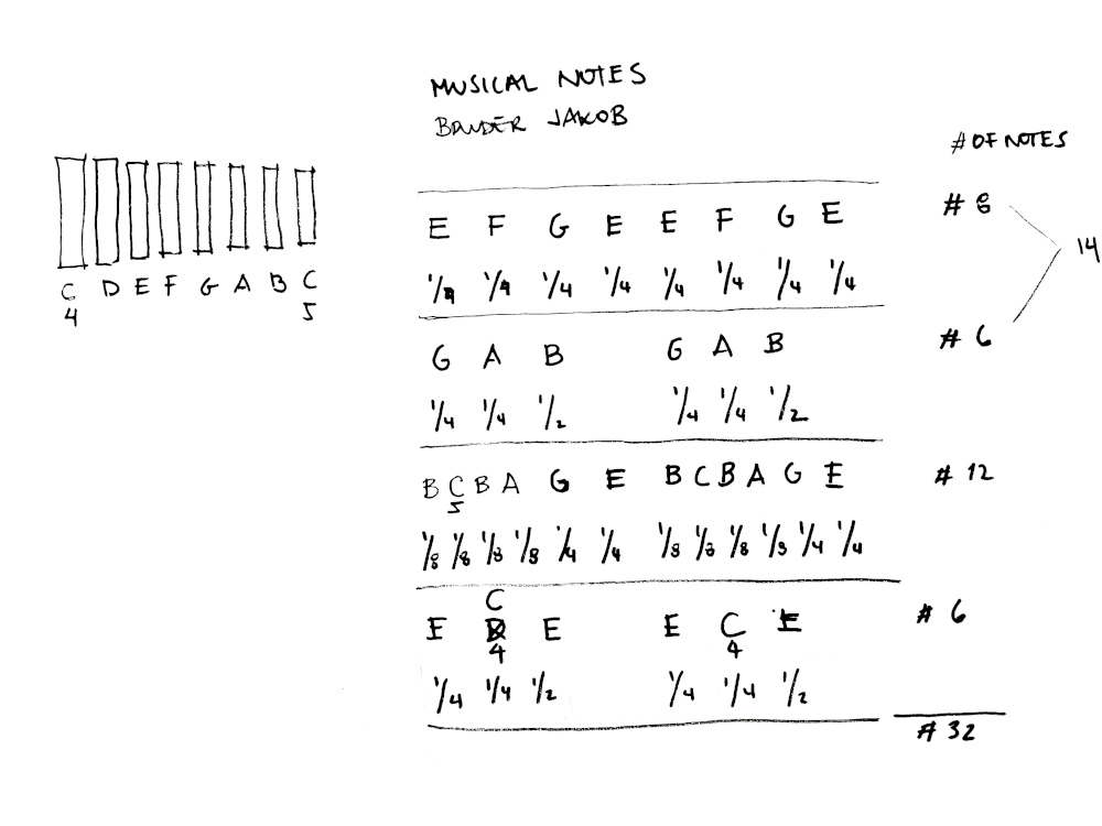 "Translating" the notes for the code
OLED DISPLAY
Font size:
To increase the font size, you need to add oled.set2X() in the setup part.
Installing the library:
The library is memory-optimized and easy to use. It can be found via the library manager in the Arduino IDE “SSD1306Ascii”.
Next, install the library. Now you can find example code to test the display. Go to File > Examples > SSD1306Ascii > HelloWorldWire
Link Git for library and example codes
CODE TO TEST THE VOLUME with a melody
/* Melody: Plays a melody created 21 Jan 2010
 *  modified 30 Aug 2011 by Tom Igoe
 *  This example code is in the public domain. http://www.arduino.cc/en/Tutorial/Tone
 *
 *  modified J. Gálvez 04.07.21: *1
 *  - 8 ohm speaker on digital pin 12
 *  - added Pitches library for music notes
 *  - changed melody and number of music notes
*/

#include "pitches.h"

// notes in the melody:
int melody_test[] = {                                     //*1 number of music notes in this sketch: 16
  NOTE_E4, NOTE_F4, NOTE_G4, NOTE_E4, NOTE_E4, NOTE_F4, NOTE_G4, NOTE_E4, 0, NOTE_G4, NOTE_A4, NOTE_B4, NOTE_G4, NOTE_A4, NOTE_B4, 0,
};

// note durations: 4 = quarter note, 8 = eighth note, etc.:
int noteDurations_test[] = {                          //*1 duration for 16 music notes
  4, 4, 4, 4, 4, 4, 4, 4, 8, 4, 4, 2, 4, 4, 2, 8
};

void setup() {
  // iterate over the notes of the melody:             //*1 Copy this part from the code in downloads
  for (int thisNote = 0; thisNote16; thisNote++) {     //*1 16 is the number of music notes


    // to calculate the note duration, take one second divided by the note type.
    //e.g. quarter note = 1000 / 4, eighth note = 1000/8, etc.
    int noteDuration = 1000 / noteDurations_test[thisNote];
    tone(12, melody_test[thisNote], noteDuration);

    // to distinguish the notes, set a minimum time between them.
    // the note's duration + 30% seems to work well:
    int pauseBetweenNotes = noteDuration * 1.23;
    delay(pauseBetweenNotes);
    // stop the tone playing:
    noTone(12);
  }
}

void loop() {
  // no need to repeat the melody.
}
CODE TO PLAY A MELODY with the buttons + OLED display
/*
 * Arduino Kexboard by https://www.hackster.io/Noshirt/arduino-keyboard-faea5d
 *
 * modified J. Gálvez 04.07.21: *1
 *  - 8 ohm speaker on digital pin 12
 *  - include library pitches.h https://www.arduino.cc/en/Tutorial/BuiltInExamples/toneMelody
 *  - add an oled display to read the notes
 *  - include adapted code HelloWorldWire.ino https://github.com/greiman/SSD1306Ascii
*/

#include "pitches.h"
const int Pin_LED = 13;           //*1 added const int for the LED and speaker
const int Pin_Speaker = 12;

const int C4 = 4;
const int D4 = 5;
const int E4 = 6;
const int F4 = 7;
const int G4 = 8;
const int A_4 = 9;
const int B4 = 10;
const int C5 = 11;

int duration(200);                 //*1 10 Miliseconds, the sound stops as soon as you stop pressing the button
                                    //*1 no int definitions for the music notes are necessary
#include "Wire.h"
#include "SSD1306Ascii.h"
#include "SSD1306AsciiWire.h"
#define I2C_ADDRESS 0x3C
// Define proper RST_PIN if required.
#define RST_PIN -1
SSD1306AsciiWire oled;

void setup() {
  Wire.begin();
  Wire.setClock(400000L);
  oled.begin(&Adafruit128x64, I2C_ADDRESS);
  oled.setFont(System5x7);

  pinMode(Pin_LED, OUTPUT);
  pinMode(C4, INPUT);           //*1 no pullup, the state of the pin is low and then goes high when the button is pressed
  pinMode(D4, INPUT);
  pinMode(E4, INPUT);
  pinMode(F4, INPUT);
  pinMode(G4, INPUT);
  pinMode(A_4, INPUT);
  pinMode(B4, INPUT);
  pinMode(C5, INPUT);
  oled.set2X();                 //*1 set up font size x2
}

void loop() {
  if (digitalRead(C4) == HIGH) {          //Reads button state when pressed
    tone(Pin_Speaker, NOTE_C4, duration); //*1 changed pin number with const int defined
    oled.clear();                         //*1 clears the displayed text for a new one
    oled.println("NOTE C4");              //*1 display the music note played
    delay(100);
  }
  if (digitalRead(D4) == HIGH) {
      tone(Pin_Speaker, NOTE_D4, duration);
      oled.clear();
      oled.println("NOTE D4");
      delay(100);
  }
  if (digitalRead(E4) == HIGH) {
      tone(Pin_Speaker, NOTE_E4, duration);
      oled.clear();
      oled.println("NOTE E4");
      delay(100);
  }
  if (digitalRead(F4) == HIGH) {
      tone(Pin_Speaker, NOTE_F4, duration);
      oled.clear();
      oled.println("NOTE F4");
      delay(100);
  }
  if (digitalRead(G4) == HIGH) {
      tone(Pin_Speaker, NOTE_G4, duration);
      oled.clear();
      oled.println("NOTE G4");
      delay(100);
  }
  if (digitalRead(A_4) == HIGH) {
      tone(Pin_Speaker, NOTE_A4, duration);
      oled.clear();
      oled.println("NOTE A4");
      delay(100);
  }
  if (digitalRead(B4) == HIGH) {
      tone(Pin_Speaker, NOTE_B4, duration);
      oled.clear();
      oled.println("NOTE B4");
      delay(100);
  }
  if (digitalRead(C5) == HIGH) {
      tone(Pin_Speaker, NOTE_C5, duration);
      oled.clear();
      oled.println("NOTE C5");
      delay(100);
  }

}
Test-it videos
Code to test the volume with a melody
Code to play a melody with the buttons + OLED display
Download
| New board designs: Schematic, Board Layout and Partlist (zip) | Download |
| Breakout board designs: Image and RML files (zip) | Download |
| Codes for a song and to play a song with the buttons (zip) | Download |